- 2009 Toyota Prius Owners Manuals
- Toyota Prius Owners Manuals
- 2008 Toyota Prius Owners Manuals
- Toyota Prius Owners Manuals
- 2013 Toyota Prius Owners Manuals
- Toyota Prius Owners Manuals
- 2004 Toyota Prius Owners Manuals
- Toyota Prius Owners Manuals
- 2001 Toyota Prius Owners Manuals
- Toyota Prius Owners Manuals
- 2005 Toyota Prius Owners Manuals
- Toyota Prius Owners Manuals
- 2015 Toyota Prius Owners Manuals
- Toyota Prius Owners Manuals
- 2012 Toyota Prius Owners Manuals
- Toyota Prius Owners Manuals
- 2002 Toyota Prius Owners Manuals
- Toyota Prius Owners Manuals
- 2010 Toyota Prius Owners Manuals
- Toyota Prius Owners Manuals
- 2014 Toyota Prius Owners Manuals
- Toyota Prius Owners Manuals
- 2006 Toyota Prius Owners Manuals
- Toyota Prius Owners Manuals
- 2003 Toyota Prius Owners Manuals
- Toyota Prius Owners Manuals
- 2007 Toyota Prius Owners Manuals
- Toyota Prius Owners Manuals
- 2011 Toyota Prius Owners Manuals
- Toyota Prius Owners Manuals
- Download PDF Manual
-
(cid:2) Long exposure to direct sunlight may cause the leather surface to harden and shrink. Keep your ve- hicle in a shaded area, especially in the summer.
(cid:2) The interior of your vehicle is apt to heat up on hot summer days, so avoid placing on the upholstery items made of vinyl or plastic or containing wax as these tend to stick to leather when warm.
(cid:2) Improper cleaning of the leather up- holstery could result in discolor- ation or staining.
If you have any questions about the cleaning of your Toyota, your local Toyota dealer will be pleased to answer them.
191
192
SECTION 7
VEHICLE MAINTENANCE AND CARE Maintenance requirements General maintenance Does your vehicle need repairing?? Emissions inspection and maintenance (I/M) programs
. . . . . . . . . . . . . . . . . . . . . . . . . . . . . . . . . . . . . . . . . . . . . . . . . . . . . . . . . . . . . . . . . . . . . . . . . . . . . . . . . . . . . . . . . . . . . . . . . . . . . . . . . . . .
194
195
197
198For scheduled maintenance information, please refer to the ”Scheduled Maintenance Guide” or ”Owner’s Manual Supplement”.
193
that both
Maintenance requirements Your Toyota vehicle has been designed for fewer maintenance requirements with long- er service intervals to save both your time and money. However, each regular mainte- nance, as well as day–to–day care, is more important than ever before to ensure smooth, trouble–free, safe, and economical driving. It is the owner’s responsibility to make sure the specified maintenance, including general maintenance service, is performed. Note the new vehicle and emission control system warranties specify that proper maintenance and care must be performed. ”Owner’s Warranty Information Booklet” or ”Owner’s Manual Supplement” warranty information. General maintenance General maintenance items are those day– to–day care practices that are important to your vehicle for proper operation. It is the owner’s responsibility to ensure that the general maintenance items are performed regularly. These checks or inspections can be done either by yourself or a qualified technician, or if you prefer, your Toyota dealer will be pleased to do them at a nominal cost.
complete
See
for
194
Scheduled maintenance The scheduled maintenance items listed in the ”Scheduled Maintenance Guide” or ”Owner’s Manual Supplement” are those required to be serviced at regular inter- vals. For details of your maintenance schedule, read the ”Scheduled Maintenance Guide” or ”Owner’s Manual Supplement”. It is recommended that only genuine Toyota parts be used for maintenance or for the repair of the emission con- trol system. The owner may elect to use non–Toyota supplied parts replacement pur- poses without invalidating the emission control system warranty. However, use of replacement parts which are not of equivalent quality may impair the effec- tiveness of the emission control sys- tems. You may also elect to have mainte- nance, replacement, or repair of the emission control devices and system performed by any automotive repair es- tablishment or individual without invali- dating this warranty. See ”Owner’s War- ranty Information Booklet” or ”Owner’s Manual Supplement” for complete war- ranty information.
for
Where to go for service? Toyota technicians are well–trained spe- cialists and are kept up to date with the latest service information through technical bulletins, service tips, and in–dealership training programs. They learn to work on Toyotas before they work on your vehicle, rather than while they are working on it. You can be confident that your Toyota dealer’s service department performs the best job to meet the maintenance require- ments on your vehicle–reliably and eco- nomically. Your copy of the repair order is proof that all required maintenance has been per- formed for warranty coverage. And if any problems should arise with your vehicle while under warranty, your Toyota dealer will promptly take care of it. Again, be sure to keep a copy of the repair order for any service performed on your Toyota. What about do–it–yourself maintenance? Many of the maintenance items are easy to do yourself if you have a little mechani- cal ability and a few basic automotive tools. Simple instructions for how to per- form them are presented in Section 8.
a
you are
If skilled do–it–yourself mechanic, the Toyota service manuals are recommended. Please be aware that do–it–yourself maintenance can affect your warranty coverage. See ”Owner’s Warranty Information Booklet” or ”Owner’s Manual Supplement” for the details.
the
items
listed,
General maintenance Listed below are the general maintenance items that should be performed as fre- quently as specified. In addition to check- ing if you notice any unusual noise, smell or vibration, you should investigate the cause or take your vehicle to your Toyota dealer or a quali- fied service shop immediately. It is recom- mended that any problem you notice be brought to the attention of your dealer or the qualified service shop for their advice.
CAUTION
Make these checks only where ade- quate ventilation can be obtained if you run the engine.
to
time
OUTSIDE THE VEHICLE Items listed below should be performed from time, unless otherwise specified. Tire pressure Check the pressure with a gauge every two weeks, or at least once a month. See page 214 for additional information.
in Section 8–2
to
for
refer
the nuts
information, please
Tire surface and wheel nuts Check the tires carefully for cuts, damage or excessive wear. See Section 8–2 for additional information. When checking the tires, make sure no nuts are missing, and check looseness. Tighten them if necessary. Tire rotation Rotate the tires according to the mainte- nance schedule. (For scheduled mainte- nance the “Scheduled Maintenance Guide” or “Own- er’s Manual Supplement”.) See page 216
in Section 8–2 for additional information. Fluid leaks Check underneath for leaking fuel, oil, wa- ter or other the vehicle has been parked for a while. If you smell fuel fumes or notice any leak, have the cause found and corrected immediately. Doors and engine hood Check that all doors and trunk operate smoothly and all lock securely. Make sure the engine hood secondary latch secures the hood from opening when the primary latch is released.fluid after
latches
195
INSIDE THE VEHICLE Items listed below should be checked regularly, e.g. while performing periodic services, cleaning the vehicle, etc. Lights Make sure the headlights, stop lights, tail lights, turn signal lights, and other lights are all working. Check headlight aim. Service reminder indicators and warning buzzers Check that all service reminder indicators and warning buzzers function properly. Steering wheel Be alert for changes in steering condition, such as hard steering or strange noise. Seats Check that all front seat controls such as seat adjusters, seatback recliner, etc. op- erate smoothly and that all latches lock securely in any position. Check that the head restraint move up and down smooth- ly and that the locks hold securely in any latched position. For rear seatbacks, check that the latches lock se- curely.
folding–down
196
Seat belts Check that the seat belt system such as buckles, retractors and anchors operate properly and smoothly. Make sure the belt webbing is not cut, frayed, worn or dam- aged. Accelerator pedal Check the pedal for smooth operation and uneven pedal effort or catching. Brake pedal Check the pedal for smooth operation and that the pedal has the proper clearance. Check the brake booster function. Brakes At a safe place, check that the brakes do not pull to one side when applied. Parking brake Check that the pedal has the proper travel and that, on a safe incline, your vehicle is held securely with only the parking brake applied.
Hybrid transaxle ”Park” mechanism Check the lock release button of the se- lector lever for proper and smooth opera- tion. On a safe incline, check that your vehicle is held securely with the selector lever in ”P” position and all brakes re- leased. IN THE ENGINE COMPARTMENT Items listed below should be checked from time to time, e.g. each time when refueling. Washer fluid Make sure there is sufficient fluid in the tank. See page 225 in Section 8–3 for additional information. Coolant level Make sure the coolant level is between the ”FULL” and ”LOW” lines on the see– through reservoir when the hybrid system is cold. See page 210 in Section 8–2 for additional information. Radiator, condenser and hoses Check that the front of the radiator and condenser are clean and not blocked with leaves, dirt, or insects. See page 211 in Section 8–2 for additional information.
Engine oil level Check the level on the dipstick with the engine turned off and the vehicle parked on a level spot. See page 208 in Section 8–2 for additional information. Exhaust system If you notice any change in the sound of the exhaust or smell exhaust fumes, have the cause located and corrected immedi- ately. (See “Engine exhaust cautions” on page 150 in Section 3.)
tip–offs
for changes
Does your vehicle need repairing? Be on the alert in perfor- mance, sounds, and visual that indicate service is needed. Some impor- tant clues are as follows: (cid:1) Engine missing, stumbling, or pinging (cid:1) Appreciable loss of power (cid:1) Strange engine noises (cid:1) A fluid leak under the vehicle (however, water dripping from the air conditioning after use is normal.)
(cid:1) Change
in exhaust sound (This may indicate a dangerous carbon monoxide leak. Drive with the windows open and have the exhaust system checked im- mediately.)
(cid:1) Flat–looking tire; excessive tire squeal
when cornering; uneven tire wear
(cid:1) Vehicle pulls to one side when driving
straight on a level road
(cid:1) Strange noises related to suspension
movement
(cid:1) Loss of brake effectiveness; spongy feeling brake pedal; pedal almost touches floor; vehicle pulls to one side when braking
(cid:1) Coolant temperature continually higher
than normal
If you notice any of these clues, take your vehicle to your Toyota dealer as soon as possible. It probably needs adjustment or repair.
CAUTION
Do not continue driving with the ve- hicle unchecked. It could result in se- rious vehicle damage and possibly personal injury.
197
The malfunction indicator lamp will go off after taking several driving trips, but the error code in the OBD system will not be cleared unless about 40 trips or more are taken. If your vehicle does not pass the I/M test and the malfunction indicator lamp does not come on, contact your Toyota dealer to prepare the vehicle for re–testing.
indicator
the malfunction
in- include OBD
Emission inspection and maintenance (I/M) programs Some states have vehicle emission spection programs which (On–Board Diagnostics) checks. The OBD system monitors the operation of the emission control system. When the OBD system determines that a problem exists somewhere in the emission control system, lamp comes on. In this case, your vehicle may the I/M test and need to be not pass repaired. Contact your Toyota dealer to service the vehicle. Even lamp does not come on, your vehicle may not pass readiness codes have not been set in the OBD system. Readiness codes are automatically set during ordinary driving. However, when the battery is disconnected or run down, the codes are erased. Also, depending on your driving habits, the codes may not be completely set. Also, if the malfunction indicator lamp had come on recently due to temporary mal- function such as a loose fuel tank cap, your vehicle may not pass the I/M test.
the malfunction
indicator
test as
I/M
the
if
198
SECTION 9
SPECIFICATIONS Dimensions and weight Electric motor Enginee Fuel Hybrid vehicle assembly Service specifications Tires Fuses
. . . . . . . . . . . . . . . . . . . . . . . . . . . . . . . . . . . . . . . . . . . . . . . . . . . . . . . . . . . . . . . . . . . . . . . . . . . . . . . . . . . . . . . . . . . . . . . . . . . . . . . . . . . . . . . . . . . . . . . . . . . . . . . . . . . . . . . . . . . . . . . . . . . . . . . . . . . . . . . . . . . . . . . . . . . . . . . . . . . . . . . . . . . . . . . . . . . . . . . . . . . . . . . . . . . . . . . . . . . . . . . . . . . . . . . . . . . . . . . . . . . . . . . . . . . . . . . . . . . . . . . . . . . . . . . . . . . . . . . . . . . . . . . . . . . . . . . . . . . . . . . . . . . . . . . . . . . . . . . . . . . . . . . . . . . . . . . . . . . . . . . . . . . . . . . . . . . . . . . . . . . . . . . . . . . . .
234
234
234
235
235
235
237
237233
Dimensions and weight Overall length mm (in.) 4305
1695
Overall width mm (in.) Overall height mm (in.) 1465
2550
mm (in.) Wheelbase 1475
mm (in.) Front tread Rear tread mm (in.) 1480
Vehicle capacity weight (occupants + luggage) kg (lb.)363
*: Unladen vehicle
(169.5) (66.7) (57.6)* (100.4) (58.1) (58.2)
(800)
Electric motor Type:
Permanent magnet motor (water cooling) Rated output: 20 kW Maximum output:
33.0/1040 – 5600 kW/rpm
Maximum torque:
350.0/0 – 400 N·m/rpm
Engine Model: 1NZ–FXE Type: 4–cylinder in line, 4 cycle, gasoline Bore and stroke, mm (in.):
75.0 x 84.7 (2.95 x 3.33)
Displacement, cm3 (cu. in.):
1497 (91.4)
234
Fuel Fuel type:
Unleaded gasoline, Octane Rating 87
(Research Octane Number 91) or higherFuel tank capacity, L (gal., lmp. gal.):
45 (11.9, 9.9)
Nickel–Metal hydride battery
Hybrid vehicle battery Type: Voltage: 7.2 V Capacity: 6.5 Ah (3HR) Quantity: 38
Overall voltage: 273.6 VService specifications ENGINE Valve clearance (engine cold), mm (in.):
Intake Exhaust
0.17—0.23 (0.007—0.009) 0.27—0.33 (0.011—0.013)
Spark plug type:
DENSO SK16R11
NGK IFR5A11Spark plug gap, mm (in.):
1.1 (0.043)
235
ENGINE LUBRICATION Oil capacity (drain and refill), L (qt, lmp. qt.):
With filter Without filter
3.7 (3.9, 3.3) 3.4 (3.6, 3.0)
Oil grade:
API grade SJ “Energy–Conserving”, SL “Energy–Conserving” ILSAC multigrade engine oil is recommended.
or
Recommended oil viscosity (SAE):
oil05u
COOLING SYSTEM Total capacity, L (qt., Imp. qt.):
HYBRID TRANSAXLE Fluid capacity, L (qt., Imp. qt.):
For gasoline engine For electric motor and inverter and converter Coolant type:
4.9 (5.2, 4.3)
4.6 (4.9, 4.1)
Fluid type:
2.6 (2.7, 2.3)
Automatic transmission fluid Type T–IV or equivalent
“TOYOTA Long Life Coolant” or equiva- lent With ethylene–glycol type coolant for a proper corrosion protection of aluminum components Do not use alcohol type antifreeze or plain water alone.
AUXILIARY BATTERY Open voltage at 20(cid:1)C (68(cid:1)F):
12.6 – 12.8 V 12.2 – 12.4 V 11.5 – 11.9 V
Fully charged Half charged Discharged
is removed with all
[Voltage that is checked 20 minutes after the key lights turned off] Charging rates:
3.5 A max.
the
236
BRAKES Minimum pedal clearance when depressed with the force of 196 N (20 kgf, 44 lbf) with the traction motor running, mm (in.):
80 (3.15)
Pedal free play, mm (in.):
1 – 6 (0.04 – 0.24)
Parking brake adjustment when depressed with the force of 294 N (30 kgf, 66 lbf):
5 – 8 clicks
Fluid type:
SAE J1703 or FMVSS No. 116 DOT 3
STEERING Wheel free play:
Less than 30 mm (1.2 in.)
Tires Tire size and pressure:
Tire size kPa (kgf/cm2 or bar, psi) Standard
Front P175/65R14 84S 240 (2.4, 35) Rear P175/65R14 84S 230 (2.3, 33)
Spare
T125/70D16 96M
420 (4.2, 60)
Wheel size: Standard Spare
14 x 5 1/2JJ 16 x 4T Wheel nut torque, N·m (kgf·m, ft·lbf):
103 (10.5, 76)
NOTE: For a complete information on tires (e.g. replacing tires or replacing wheels), see ”Checking tire pres- ”Aluminum wheel sure” precautions”, page 214 through 219 in Section 8–2.
through
Fuses
90p005a
Engine compartment
1. ABS NO.4 10 A: Anti–lock brake sys-
tem
2. HTR NO.1 30 A: Air conditioning sys-
tem
3. HTR NO.2 30 A: Air conditioning sys-
tem
4. DRL 7.5 A: Daytime running light sys-
tem
5. CDS FAN 30 A: Air conditioning sys-
tem
6. HORN 10 A: Horn 7. HEAD HI (RH) (Vehicles with Daytime light system only) 10 A:
running Right–hand headlight (high beam)
237
90p006a
90p007a
90p008a
Engine compartment
Instrument panel
Trunk
8. AM2 15 A: Starting system, multiport fuel injection system/sequential multi- port fuel injection system, hybrid ve- hicle immobiliser system
9. THRO 15 A: Electronic throttle control
system
10. HEAD (RH) (Vehicles without DAY- TIME RUNNING LIGHT SYSTEM) or HEAD LO (RH) (Vehicles with DAY- TIME RUNNING LIGHT SYSTEM) 10
A: Right–hand headlight11. HEAD HI (LH) (Vehicles without DAY- TIME RUNNING LIGHT SYSTEM) 10
A: Left–hand headlight (high beam)238
12. BATT FAN 10 A: Battery cooling fan 13. ABS NO.3 20 A: Hydraulic brake
booster
14. HV 20 A: Hybrid system 15. EFI 15 A: Multiport fuel injection sys- injection
tem/sequential multiport system
fuel
16. HEAD (LH) (Vehicles without DAY- TIME RUNNING LIGHT SYSTEM) or HEAD LO (LH) (Vehicles with DAY- TIME RUNNING LIGHT SYSTEM) 10
A: Left–hand headlight17. DOME 15 A: Audio system, mult–infor- mation display, interior light, trunk light, power window system, wireless remote control system
18. TURN–HAZ 10 A: Turn signal lights,
Emergency flasher
19. PANEL 5 A: Audio system, ashtray light, headlight beam level control sys- tem, emergency flasher
20. GAUGE 10 A: Gauge and meter, emer- flasher, rear window defogger, gency service reminder indicator and warning buzzers, back–up light, power window system, air conditioning system
36. HTR NO.3 50 A: Air conditioning sys-
tem
37. EMPS 50 A: Electric power steering 38. ABS NO.1 40 A: Anti–lock brake sys-
tem
39. MF HEAD 30 A: Daytime running light
system
40. HTR 50 A: Air conditioning system 41. RDI 30 A: Electric cooling fan 42. ABS NO.2 30 A: Hydraulic brake
booster
21. HTR 10 A: Air conditioning system 22. TAIL 7.5 A: Parking lights, tail lights, license plate lights, side marker lights 23. ECU–IG 5 A: Air conditioning system, anti–lock brake system, electric power steering, daytime running light system 24. STOP 15 A: Stop lights, high mounted
stoplights, anti–lock brake system
25. ACC 10 A: Anti–lock brake system warning light, clock, audio system, mul- ti–information display, shift lock system
26. WIPER 30 A: Windshield wiper 27. ECU–B 7.5 A: Air conditioning system, daytime running light system, electric power steering system, hybrid vehicle immobiliser system
28. CIG 15 A: Power outlet 29. WASHER 15 A: Washer 30. DOOR 30 A: Power door lock system 31. SRS ACC 10 A: SRS airbags, seat
belt pretensioners
32. OBD II 7.5 A: No circuit 33. PWR1 20 A: Power window system 34. AM1 5 A: “ACC”, “CIG”, “SRS ACC”, “WASHER”, “HTR”, “WIPER”, “ECU–IG” and “GAUGE” fuses
35. DC/DC–S 5 A: Inverter and converter
239
240
SECTION 10
REPORTING SAFETY DEFECTS FOR U.S. OWNERS AND UNIFORM TIRE QUALITY GRADING Reporting safety defects for U.S. owners Uniform tire quality gradingg
. . . . . . . . . . . . . . . . . . . . . . . . . . . . . . . . . . . . . . . . . . . . . . . . . . . . . . .
242
242241
To contact NHTSA, you may either call the Auto Safety Hotline toll–free at 1–800–424–9393 (or 366–0123
in Washington, D.C. area) or write to: NHTSA, U.S. Department of Transportation, Washington, D.C. 20590. You can also obtain other information about motor vehicle safety from the Hotline.Reporting safety defects for U.S. owners If you believe that your vehicle has a defect which could cause a crash or could cause injury or death, you should immediately inform the Na- tional Highway Traffic Safety Ad- ministration (NHTSA) in addition to notifying Toyota Motor Sales, U.S.A., (Toll–free: Inc. 1–800–331–4331).
If NHTSA receives similar com- plaints, it may open an investiga- tion, and if it finds that a safety de- fect exists in a group of vehicles, it may order a recall and remedy campaign. However, NHTSA cannot become involved in individual prob- lems between you, your dealer, or Toyota Motor Sales, U.S.A., Inc.
242
Uniform tire quality grading This information has been prepared in ac- cordance with regulations issued by the National Highway Traffic Safety Adminis- tration of the U.S. Department of Trans- portation. It provides the purchasers and/ or prospective purchasers of Toyota vehicles with information on uniform tire quality grading. Your Toyota dealer will help answer any questions you may have as you read this information. DOT quality grades—All passenger car tires must conform to Federal Safety Requirements these grades. Quality grades can be found where applicable on the tire sidewall between tread shoulder and maximum section width. For example: Treadwear 200 Traction AA Temperature A.
in addition
to
from
Tread wear—The tread wear grade is a comparative rating based on the wear rate of the tire when tested under controlled conditions on a specified government test course. For example, a tire graded 150
would wear one and a half (1–1/2) times as well on the government course as a tire graded 100. The relative performance of tires depends upon the actual condi- tions of their use, however, and may de- part significantly the norm due to variations in driving habits, service prac- tices and differences in road characteris- tics and climate. Traction AA, A, B, C—The traction grades, from highest to lowest, are AA, A, B, and C, and they represent the tire’s ability to stop on wet pavement as mea- sured under controlled conditions on spe- cified government test surfaces of asphalt and concrete. A tire marked C may have poor traction performance. Warning: The traction grade assigned to this is based on braking (straight ahead) traction tests and does not include cornering (turning) traction.tire
Temperature A, B, C—The temperature grades are A (the highest), B, and C, representing the tire’s resistance to the generation of heat and its ability to dissi- pate heat when tested under controlled conditions on a specified indoor laboratory test wheel. Sustained high temperature can cause the material of the tire to de- generate and reduce tire life, and exces- sive temperature can lead to sudden tire failure. The grade C corresponds to a lev- el of performance which all passenger car tires must meet under the Federal Motor Vehicle Safety Standard No. 109. Grades B and A represent higher levels of perfor- mance on the laboratory test wheel than the minimum required by law. Warning: The temperature grades for this tire are established for a tire that is prop- erly inflated and not overloaded. Exces- sive speed, underinflation, or excessive loading, either separately or in combina- tion, can cause heat buildup and possible tire failure.
243
244
SECTION 1– 1
FEATURES ON NEW TOYOTA VEHICLE Overview of instruments and controls Instrument panel overvieww Instrument cluster and multi–information display overview Indicator symbols on the instrument panel and multi–information display
. . . . . . . . . . . . . . . . . . . . . . . . . . . . . . . . . . . . . . . . . . .
. . . . . . . . . . . . . . . . . . . . . . . . . . . . . . . . . . . . . . . . . . . . . . . . . . . . . .
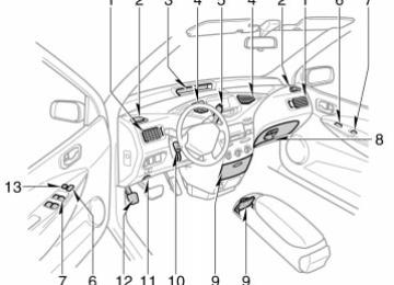
1. Side vents
2. Side defroster outlets
3. Instrument cluster
4. Center vents
5. Running mode selector lever
6. Power door lock switches 7. Power window switches
8. Glove box
9. Auxiliary boxes
10. Tilt steering lock release lever
11. Hood lock release lever
12. Parking brake pedal
13. Window lock switch
Instrument panel overview
11p003b
11p001g
1. Headlight and turn signal switch
2. Wiper and washer switch
3. Rear window defogger switch
4. Trip meter reset button
5. Emergency flasher switch
6. Multi–information display 7. Switching km/h MPH button
8. Security indicator light
9. Clock
10. Car audio
11. Air conditioning controls
12. Auxiliary box
13. Power outlet
14. Ignition switch
15. Cruise control switch
16. Power rear view mirror control switch
17. Instrument panel light control dial
Instrument cluster and multi–information display overview
1. Service reminder indicators and indica-
tor lights
2. Speedometer
3. Fuel gauge
4. Odometer and trip meter
5. Outside temperature display
11p002f
Indicator symbols on the instrument panel and Multi–information display
or
Brake system warning light* 1
Seat belt reminder light* 1
Front passenger’s seat belt reminder light* 1
Low engine oil pressure warning light* 1
Master warning light* 1
or
Anti–lock brake system warning light* 1
Discharge warning light* 1
Open door warning light* 1
Low fuel level indicator light* 1
SRS warning light* 1
Low coolant temperature indicator light (in blue)* 1
High coolant temperature warning light (in red)* 1Turn signal indicator lights
Headlight high beam indicator light
Malfunction indicator lamp* 1
Headlight indicator light
* 1: For details, see ”Service reminder indicators and warning buzzers— —Instrument cluster” on page 91 in Section 2–4. * 2: For details, see “Service reminder indicators and warning buzzers— —Multi–information display” on page 97 in Section 2–4. If this light flashes, see ”Cruise control” on page 107 in Section 2–5.
* 3:
Tail light indicator light
Cruise control indicator light* 3
Running mode position indicator light
Driving ready light
Output control warning light* 1
Hybrid vehicle battery warning light* 2
Power steering warning light* 2
Hybrid system warning light* 2
SECTION 1– 2
FEATURES ON NEW TOYOTA VEHICLE Toyota hybrid system Toyota hybrid system Toyota hybrid system operating conditionn Starting your vehicle For efficient use of your vehicle Precautions for use
. . . . . . . . . . . . . . . . . . . . . . . . . . . . . . . . . . . . . . . . . . . . . . . . . . . . . . . . . . . . . . . . . . . . . . . . . . . . . . . . . . . . . . . . . . . . . . . . . . . . . . . . . . . . . . . . . . . . . . . . . . . . . . . . . . . . . . . . . . . . . . . . . . . . . . . . . . . . . . . . . . . . . . . . . . . . . . . . .
11
11
12Toyota hybrid system operating condition Basic operations are described below. Be- sides, Toyota hybrid system performs vari- ous controls depending on the operating condition, such as at the time of hybrid system starting, at the time of charging should be required, at the time of the air conditioning is in use, etc.
Since the battery is charged by the gasoline engine as needed, it does not require charging from the outside like an electric vehicle. In this way, greatly improved fuel economy and reduced emissions are attained. If you do not use the vehicle for a long time, the hybrid vehicle battery will dis- charge and the battery condition is liable to decline.
to
the
improve
Toyota hybrid system Toyota hybrid system combines the gasoline engine and the electric motor power fuel economy largely and minimize the emissions as well as to provide higher power perfor- mance than the ordinary gasoline–pow- ered vehicles. Depending on the driving condition, the vehicle runs on the best combination of; (cid:1) Gasoline engine power (cid:1) Electric motor power generated by
the gasoline engine
(cid:1) Electric motor power of the hybrid
vehicle battery
Furthermore, the energy is effectively used in the following ways: (cid:1) When stopping the vehicle, the gaso-
line engine is automatically stopped.
(cid:1) When decreasing the speed by apply- ing the brakes, electricity converted from the turning force of the wheels is stored the hybrid vehicle battery. (This is called regenerative brake.)
in
12p016a
12p017a
12p018a
Electric power in use
Gasoline power in use
Electric and gasoline power in use
When starting or backing up, etc., the gasoline engine efficiency worsens, so the vehicle runs on electric power from hybrid vehicle battery.
During normal driving, the vehicle runs mainly on gasoline power. However, the electric motor, using electric power gener- ated by the gasoline engine, makes up for any deficiency of gasoline power. The vehicle controls the optimum ratio of the gasoline and electric power to help save energy more effectively.
When driving at full throttle, electric power is further applied from the hybrid vehicle battery. Vehicle performance impro- ves.
12p019a
12p020a
12p030
Storing electric power
Not in use
When decreasing speed or applying the brakes, the turning force of the wheels the electric motor operate as a makes generator and additional electricity is stored in the hybrid vehicle battery (regen- erative brake).
When stopping, the gasoline engine auto- matically shuts off.
Charging hybrid vehicle battery When the hybrid vehicle battery power is insufficient, the gasoline engine charges the hybrid vehicle battery. The system al- ways supplies electricity at a constant lev- el.
10
in
the
from
“ON”
ignition key
“P” position only. When
Starting your vehicle Turn to “START” with the running mode selector lever the “READY” light flashes and stays on and a beep sounds after a few seconds, the hybrid system starts. (If the ambient tem- perature is low such as during winter con- ditions, the “READY” light is on.) Being different from ordinary vehicles, you cannot start your vehicle with the running mode selector le- ver in “N” position. (For details, see “How to start the hybrid system—” on page 162
in Section 4.)time until
it may
take
For efficient use of your vehicle Drive your vehicle with a smooth accel- eration and deceleration. (cid:1) When driving, energy is effectively re- covered through the regenerative brake as the vehicle decelerates. However, for more efficient use, do not acceler- ate or decelerate your vehicle more than necessary.
(cid:1) By avoiding abrupt acceleration and de- celeration, the remaining capacity of the hybrid vehicle battery can be pre- served and it makes it possible to run the vehicle utilizing the gasoline engine and the electric power from the hybrid vehicle battery.
(cid:1) The remaining capacity of the hybrid vehicle battery can be confirmed on the energy monitor screen of the multi– information display. See “Information” on 113 page in Section 2–6 for details. As the way in which you drive may decrease the remaining capacity of the hybrid vehicle battery and reduce fuel economy, drive your vehicle without abrupt acceleration or deceleration.
Use the “A/C” mode (with the “A/C” button only on) when you use the air conditioning. (cid:1) As
the gasoline engine starts and stops automatically in this mode, eco- nomical driving with less emissions is possible.
is
frequently used. Use
(cid:1) In the “MAX” mode (with the “A/C” but- ton and “MAX” button on), the gasoline engine this mode only when you need to operate the air conditioning fully such as when you should dehumidify or when you are under a burning sun.
When parking, be sure to put the run- ning mode selector lever in “P” posi- tion. While driving, use “D” position. (cid:1) With the selector lever in “N” position, the gasoline engine operates but elec- tricity generated. The constant electrical power remaining in the hybrid vehicle battery becomes in- sufficient and the battery will be dis- charged.
cannot
be
11
If the output control warning light ( comes on in the instrument cluster, the hybrid vehicle battery temperature is low or high, or the hybrid vehicle bat- tery capacity is decreased with the se- lector lever at “R” during driving. As it does not indicate the failure of the sys- tem, you can continue driving but avoid hard acceleration because the power is insufficient (which is caused by the bat- tery power deterioration).
Precautions for use The vehicle runs in combination with the gasoline and electric power. Pay special attention to the following items. Be careful of a high voltage and high temperature. Your vehicle is equipped with the orange colored cables connected the hybrid vehicle battery which contain a high volt- age (about 300 V) and to other high volt- age parts.
to
CAUTION
Do not touch or come in contact with orange cables or battery terminals. Electric shock may cause serious in- jury or death. Read all caution labels.
A electric motor, coolant radiator and some other parts reach high temperature when you are driving. Caution labels are applied to these parts. Carefully observe the instructions on these caution labels.
(cid:1) The hybrid system automatically con- trols the level of electrical power re- maining in the hybrid vehicle battery. With the selector lever in a position other than “N”, electricity is generated and charging occurs when the level of electrical power in the hybrid vehicle battery decreases. It is unnecessary to charge the hybrid vehicle battery from outside.
INFORMATION: The gasoline engine starts and stops automatically. (It stops during a low load driving, deceleration or when the vehicle stopped.) If the “READY” light remains on, you can start your vehicle using the electric motor even with the gasoline engine stopped. The gasoline engine may not stop auto- matically in the following conditions:
(cid:2) During under gasoline engine warm–
up
(cid:2) During hybrid vehicle battery charg-
ing
(cid:2) When the air conditioning is used in the “MAX” mode, the gasoline engine is frequently used.
12
CAUTION
Hybrid vehicle battery
remove or disassemble
Never the high voltage parts, high voltage cables (orange color) and their con- nectors. It may cause death or seri- ous injury.
Service plug
12p007d
High volt- age cables
Inverter unit
Do not touch the service plug. The service plug is installed in the left side trim of the trunk. It is provided to shut out high voltage current of the hybrid vehicle battery when in the vehicle need of repairs at a Toyota dealer.
is
CAUTION
(cid:1) The shaded parts in the illustration
are subjected to a high voltage.
(cid:1) Inappropriate handling may cause an electric shock resulting in seri- ous injury or death. Never touch any item in shaded area.
Keep your hybrid vehicle’s driving char- acteristics in mind. (cid:1) As the vehicle runs with both the gaso- line engine and electric motor, you may hear a motor sound coming from the engine compartment.
(cid:1) When the ignition switch is turned to on or off, you may hear a sound com- ing from the hybrid vehicle battery in the trunk. However, this does not indi- cate any trouble.
(cid:1) If the “READY” light is on, you can the gasoline engine
start even with stopped.
(cid:1) When the hybrid vehicle battery tem- perature is low or high, or the hybrid vehicle battery capacity is decreased with the selector lever at “R” during driving, the output control warning light comes on and the output might be lim- ited for longer battery charge life.
(cid:1) If the output control warning light is on, drive your vehicle without hard accel- eration. The output power will be limit- ed particularly when backing up.
13
(cid:1) When you put the running mode selec- tor lever in “B” position and release your foot from the accelerator pedal, engine braking will be applied. Howev- er, during the high speed driving you may feel that deceleration by engine braking is less than that of ordinary vehicle.
is decreased with
Drive your vehicle without hard accel- if the output control warning eration light ( ) is on. The hybrid vehicle battery temperature is low or high, or the hybrid vehicle battery capacity the selector lever at “R” during driving. If this occurs, the output control warning light comes on. If the output control warning light is on, the hybrid system output is limited. Drive your vehicle without hard acceleration. Vehicle performance might be reduced sig- nificantly especially when backing up. Be sure to put the running mode selec- tor lever in “P” position when parking. With the selector lever in “N” position, the hybrid vehicle battery assembly is not charged, even if the gasoline engine is operating. You cannot run your vehicle if the selector lever is left in “N” position for a long time because the hybrid vehicle battery assembly will be discharged.
14
When you leave your vehicle, apply the parking brake with the running mode selector lever in “P” position and be sure to remove the key and lock all the doors. When you leave the the ignition key in the “ACC” or “ON” position if the hybrid sys- tem is not operating, the hybrid system may not start because the auxiliary bat- tery will be discharged.
CAUTION
(cid:1) When you
leave your vehicle, be
sure to shut off the hybrid system.
lever
(cid:1) Be sure to put the running mode selector in “P” position be- cause the vehicle can start with the “READY” light on and the engine stopped (no engine sound and vibration). When the “READY” light is on, if you leave your vehicle with the running mode selector lever in a position other than “P” and “N”, the vehicle will creep and start abruptly with the accelerator pedal being depressed by mistake. It may cause death or serious injury.
12p008a
If the multi–information display shows a message, the master warning light ) comes on in the instrument clus- ter. Read the message and follow the instruction. (cid:1) When you leave your vehicle, or stop or park for a while, put the selector lever in “P”.
(cid:1) Charging is necessary. With the selec- tor lever in “N” position, charging will not be applied. The electric generator operates in “P”, “D” or “B” position. If you continue driving, put the selector lever in “D” or “B” position and depress the accelerator pedal. Do not leave it in “N” position. When driving in traffic jam, run in “D” position.
12p009c
Do not put the luggage on the package tray behind the rear seatback. (cid:1) An air vent is provided on the package tray behind the rear seatback to cool the hybrid vehicle battery. If this vent is covered with something, the hybrid vehicle battery will overheat resulting in a reduction of the output performance of the hybrid system.
(cid:1) Do not apply water or put foreign ob- jects over the air vent. Otherwise, it may affect the hybrid vehicle battery adversely and cause damage.
(cid:1) You may hear a cooling fan noise from
the air vent.
For vehicle repairs or maintenance, be sure to consult your Toyota dealer. If your vehicle is beyond repair because of accident or something, be sure to consult your Toyota dealer. As sealed Nickel–Metal hydride batteries are used, be sure to consult your Toyota dealer when disposing of your vehicle.
CAUTION
If you are involved in an accident, follow these precautions. (cid:1) Move the vehicle to a safe place and perform the followings to re- duce the risk of high voltage elec- tricity leakage. (cid:1) Depress the brake pedal and put the
selector lever in “P” position.
(cid:1) Apply the parking brake. (cid:1) Turn the ignition switch to “LOCK”
and remove the key.
(cid:1) If your vehicle has experienced ma- jor damage, you may get an electric shock. To prevent this, never touch the high voltage parts (hybrid ve- hicle battery assembly, etc.) or cables (orange color) connecting these parts. If some exposed elec- tric wiring is protruding inside or outside of the vehicle, an electric shock may also occur. Never touch them.
(cid:1) If the fluid leaks or gets in some part of the vehicle, never touch it because it may be electrolyte (strong alkali) from the hybrid ve- hicle battery. If it gets on your skin or eyes, wash off immediately with a large amount of water, if possible, with boric acid solution, and get immediate medical attention in or- der to help avoid serious injury.
(cid:1) If a vehicle fire occurs, extinguish it using a fire extinguisher for the exclusive use on electric fires. As a small amount of water may be dangerous, use a large amount of water, for example from a fire hy- drant, or wait fire–fighting team arrival.
for a
15
towing,
(cid:1) When your vehicle needs
to be towed, do it with the front wheels or all four wheels raised. If the front wheels are on the ground when the electric motor may continue to generate electricity which could cause leakage of elec- tricity and a fire depending on the degree of damage. See “If your ve- hicle needs to be towed” on page 180 in Section 5.
16
SECTION 2– 1
OPERATION OF INSTRUMENTS AND CONTROLS Keys and Doors Keys Hybrid vehicle immobiliser system Side doors Power windows Trunk lid Hood Theft deterrent system Fuel tank cap
. . . . . . . . . . . . . . . . . . . . . . . . . . . . . . . . . . . . . . . . . . . . . . . . . . . . . . . . . . . . . . . . . . . . . . . . . . . . . . . . . . . . . . . . . . . . . . . . . . . . . . . . . . . . . . . . . . . . . . . . . . . . . . . . . . . . . . . . . . . . . . . . . . . . . . . . . . . . . . . . . . . . . . . . . . . . . . . . . . . . . . . . . . . . . . . . . . . . . . . . . . . . . . . . . . . . . . . . . . . . . . . . . . . . . . . . . . . . . . . . . . . . . . . . . . . . . . . . . . . . . . . . . . . . . . . . . . . . . . . . . . . . . . . . . . . . . . . . . . . . . . . . . . . . . . . . . . . . . . . . . . . . . . . . . . . . . . . . . . . . . . . . . . . . . . . . . . . . . . . . . . . . . . . . . . . .
18
20
22
28
31
32
34
3517
Keys
21p001
Your vehicle is supplied with two kinds of keys. 1. Master key (black)—This key works in lock. Your Toyota dealer will every need it to make you a new key with built–in transponder chip.
2. Sub key (gray)—This key will not work
in the trunk.
A transponder chip for the hybrid vehicle immobiliser system has been filled in the head of the master and sub keys. These chips are required for the system to func- tion correctly, so be careful not to lose these keys. If you make your own dupli- cate key, you will not be able to cancel the system or start the hybrid system. To protect items locked in the trunk when someone else parks your vehicle for you (such as an attendant or valet), leave the sub key with them. Since the doors and trunk can be locked without a key, you should always carry a spare master key in case you accidentally lock your keys inside the vehicle.
21p002a
NOTICE
When using a key containing a trans- ponder chip, observe the following precautions: (cid:2) When starting the hybrid system, do not use the key with a key ring resting on the key grip and do not press the key ring against the key grip. Doing so may prevent the hy- brid system from starting.
18
21p003a
21p004a
(cid:2) Do not bend the key grip.
(cid:2) When starting the hybrid system, do not use the key in proximity with other transponder keys (includ- ing keys of other vehicles) and do not press other key plates against the key grip. Doing so may prevent the hybrid system from starting or, may cause the hybrid system to stop soon after it starts. If this hap- pens, remove the key once and then insert it again after taking off other transponder keys (including keys of other vehicles) from the ring or while gripping or covering them with your hand to start the hybrid system.
(cid:2) Do not cover the key grip with any material that cuts off electromagnet- ic waves.
(cid:2) Do not knock the key hard against
other objects.
(cid:2) Do not leave the key exposed to high temperatures for a long period, such as on the dashboard or hood under direct sunlight.
(cid:2) Do not put the key in water or
wash it in an ultrasonic washer.
(cid:2) Do not use the key with electromag-
netic materials.
19
Hybrid vehicle immobiliser system
21p005
21p006
21p007a
KEY NUMBER PLATE Your key number is shown on the plate. Keep the plate in a safe place such as your wallet, not in the vehicle. If you should lose your keys or if you need additional keys, duplicates can be made by a Toyota dealer using the key number. We recommend that you write down the key number and keep it in a safe place.
The hybrid vehicle immobiliser system is a theft prevention system. When you insert the key in the ignition switch, the transponder chip in the key’s head transmits an electronic code to the ve- hicle. The hybrid system will start, only when the electronic code in the chip corresponds to the registered ID code for the vehicle.
20
indicator
light will start
The system is automatically set when the key is removed from the ignition switch. The flashing to show the system is set. If either of the following indicator condi- tions occurs, contact your Toyota dealer. (cid:1) The light stays on except when the theft deterrent system is set- ting or activating. (See ”Theft deterrent system” on page 34 in this section.)
indicator
(cid:1) The indicator light does not start flash- ing when the key is removed from the ignition switch.
(cid:1) The indicator light flashes unsteady.
Inserting the registered key in the ignition switch automatically cancels the system, which enables the hybrid system to start. The indicator light will go off. For your Toyota dealer to make you a new key with built–in transponder chip, your dealer will need your key number and master key. However, there is a limit to the number of additional keys your Toyota dealer can make for you. If you make your own duplicate key, you will not be able to cancel the sys- tem or start the hybrid system.
For vehicles sold in U.S.A.
For vehicles sold in Canada
FCC ID: MOZ RI–9BTY–1
MADE IN JAPAN This device complies with Part 15 of the FCC Rules. Operation is subject to the following two conditions: (1) This device may not cause harmful interference, and (2) this device must accept any interference received, includ- ing interference that may cause unde- sired operation.This device complies with RSS–210 of industry Canada. Operation is subject to the following two conditions: (1) This device may not cause interfer- ence, and (2) this device must accept any interference that may cause undesired operation of the device.
interference,
including
NOTICE
CAUTION
Do not modify, remove or disas- semble the hybrid vehicle immobiliser system. If any unauthorized changes or modifications are made, the proper operation of the system cannot be guaranteed.
Changes or modifications not ex- pressly approved by the party respon- sible for compliance could void the user’s authority to operate the equip- ment.
21
Side doors—
21p008
The driver’s window can be opened and closed from outside the vehicle using a key. For details, see “Power windows” on page 28 in this section.
LOCKING AND UNLOCKING WITH KEY Insert the key into the keyhole and turn it. To lock: Turn the key forward. To unlock: Turn the key backward. All lock and unlock simulta- neously with either front door. In the driv- er’s door lock, turning the key once will unlock the driver’s door and twice in suc- cession will unlock all the doors simulta- neously.
the doors
22
21p009
IN-
LOCKING AND UNLOCKING WITH SIDE LOCK KNOB Move the lock knob. To lock: Push the knob forward. To unlock: Pull the knob backward. The driver’s door can be opened by pull- ing the inside door handle even if the lock knob is depressed. Closing the door with the lock knob in the lock position will also lock the door. Be careful not to lock your keys in the ve- hicle. The door cannot be locked if you leave the key in the ignition switch.
21p010
Driver’s side
21p011
Passenger’s side
LOCKING AND UNLOCKING WITH POWER DOOR LOCK SWITCH Push the switch. To lock: Push the switch on the front side. To unlock: Push the switch on the rear side. All the doors lock or unlock simultaneous- ly.
21p012a
to
the
lock
lever
the “LOCK”
REAR DOOR CHILD–PROTECTORS Move position as shown on the label. This feature allows you to lock a rear door so it can be opened from the outside only, not from inside. We recommend us- ing this feature whenever small children are in the vehicle.
23
CAUTION
Before driving, be sure that the doors are closed and locked, especially when small children are in the ve- hicle. Along with the proper use of seat belts, locking the doors helps prevent the driver and passengers from being thrown out from the ve- hicle during an accident. It also helps prevent the doors from being opened unintentionally.
24
—Wireless remote control
21p013e
Locking operation
21p014d
Unlocking operation
THE
AND
UNLOCKING
The wireless remote control system is designed to lock or unlock both doors, or activate the theft deterrent system from a distance within approximately 1
m (3 ft.) of the vehicle. LOCKING DOORS To lock and unlock all the doors, push the switches of the transmitter slowly and securely. To lock: Push the “LOCK” switch. All the doors are locked simultaneously. At this time the parking lights, side marker lights, license plate lights and tail lights will flash once. Check to see that the doors are securely locked. If either door is not securely closed, lock- ing cannot be performed by the “LOCK” switch.the
to unlock
the “UNLOCK” switch
“UNLOCK” switch To unlock: Push once the only driver’s door. Pushing the switch twice within 3 seconds unlocks all the doors simultaneously. Each time the “UNLOCK” switch is pushed, the parking lights, side marker lights, license plate lights and tail lights will flash twice. When is pressed the interior light comes on. The lights re- mains on for about 15 seconds unless either door is opened then and closed. (For “Interior lights” on page 84 in Section 2–3.) You have 30 seconds to open a door after using the wireless remote unlock feature. If a door is not opened by then, all the doors will be automatically locked again. If the “LOCK” or “UNLOCK” switch is kept pressed in, the locking or unlocking opera- tion is not repeated. Release the button and then push again.
information,
further
see
21p015
WIRELESS REMOTE CONTROL TRANS- MITTER The wireless remote control transmitter is an electronic component. Observe the fol- lowing instructions in order not to cause damage to the transmitter. (cid:1) Do not leave the transmitter on places the temperature becomes high
where such as on the dashboard.
(cid:1) Do not disassemble it. (cid:1) Avoid knocking
it hard against other
objects or dropping it.
flashes
to break
“PANIC” SWITCH Pushing the “PANIC” switch blows the horn intermittently and the headlights and tail lights. The “PANIC” switch is used to deter ve- hicle theft when you witness anyone at- tempting into or damage your vehicle. The alarm will have for one minute. To stop alarm midway, push the “PANIC” or “UNLOCK” switch once again, unlock any door with the key or transmitter, or turn the ignition key from the “LOCK” to “ON” position. The “PANIC” mode does not work when the ignition key is in the “ON” position.
for
transmitters
(cid:1) Avoid putting it in water. You can use up to 4 wireless remote con- the same vehicle. trol Contact your Toyota dealer for detailed information. If the wireless remote control transmitter does not actuate the doors or alarm, or operate from a normal distance. (cid:1) Check for closeness to a radio trans- mitter such as a radio station or an airport which can interfere with normal operation of the transmitter.
(cid:1) The batteries may have been con- sumed. Check the battery in the trans- mitter. To replace the battery, see “RE- PLACING TRANSMITTER BATTERY” below.
25
interference
NOTICE: This equipment has been tested and found to comply with the limits for a Class B digital device, pursuant to Part 15 of the FCC Rules. These limits are designed to provide reasonable protec- tion against harmful in a residential installation. This equipment generates, uses and can radiate radio frequency energy and, if not installed and used in accordance with the instruc- tions, may cause harmful interference to radio communications. However, there is no guarantee that interference will not occur in a particular installation. If this equipment does cause harmful interfer- ence television reception, which can be determined by turning the equipment off and on, the user is en- couraged to try to correct the interfer- ence by one or more of the following measures:
to radio or
If you lose your transmitter, contact your Toyota dealer as soon as possible to avoid the possibility of theft, or an acci- dent. (See “If you lose your wireless re- mote control transmitter” on page 183 in Section 5.) For vehicles sold in U.S.A.
This device complies with Part 15 of the FCC Rules. Operation is subject to the following two conditions: (1) This device may not cause harmful interference, and (2) this device must accept any interference received, includ- ing interference that may cause unde- sired operation.
26
(cid:1) Reorient or relocate the receiving an-
tenna.
(cid:1) Increase the separation between the
equipment and receiver.
(cid:1) Connect the equipment into an outlet to
on a circuit different which the receiver is connected.
from
that
(cid:1) Consult the dealer or an experienced
radio/TV technician for help.
FCC WARNING: Changes or modifications not ex- pressly approved by the party respon- sible for compliance could void the user’s authority to operate the equip- ment.
For vehicles sold in Canada
(1)
Operation is subject to the following two conditions: this device may not cause interference, and (2) this device must accept any interference, including interference that may cause undesired operation of this device.
REPLACING TRANSMITTER BATTERY For replacement, use CR2016 lithium bat- tery or equivalent.
CAUTION
Special care should be that small children do not swallow the re- moved transmitter battery or compo- nents.
taken
NOTICE
(cid:2) During replacing the transmitter battery, do not push the “LOCK”