- 2009 Toyota Prius Owners Manuals
- Toyota Prius Owners Manuals
- 2008 Toyota Prius Owners Manuals
- Toyota Prius Owners Manuals
- 2013 Toyota Prius Owners Manuals
- Toyota Prius Owners Manuals
- 2004 Toyota Prius Owners Manuals
- Toyota Prius Owners Manuals
- 2001 Toyota Prius Owners Manuals
- Toyota Prius Owners Manuals
- 2005 Toyota Prius Owners Manuals
- Toyota Prius Owners Manuals
- 2015 Toyota Prius Owners Manuals
- Toyota Prius Owners Manuals
- 2012 Toyota Prius Owners Manuals
- Toyota Prius Owners Manuals
- 2002 Toyota Prius Owners Manuals
- Toyota Prius Owners Manuals
- 2010 Toyota Prius Owners Manuals
- Toyota Prius Owners Manuals
- 2014 Toyota Prius Owners Manuals
- Toyota Prius Owners Manuals
- 2006 Toyota Prius Owners Manuals
- Toyota Prius Owners Manuals
- 2003 Toyota Prius Owners Manuals
- Toyota Prius Owners Manuals
- 2007 Toyota Prius Owners Manuals
- Toyota Prius Owners Manuals
- 2011 Toyota Prius Owners Manuals
- Toyota Prius Owners Manuals
- Download PDF Manual
-
repairs and modifications.
22p029c
(cid:1) Do not attach a cup holder or any other device or object on or around the door. When the side airbag in- flates, the cup holder or any other device or object will be thrown with great force or the side airbag may not activate correctly, resulting in injury. Likewise, death or serious the driver and front passenger should not hold objects their arms or on their knees.
in
NOTICE
Do not perform any of the following changes without consulting your Toyota dealer. Such changes can interfere with proper operation of the SRS side airbag system in some cases. (cid:2) Installation of electronic devices such as a mobile two–way radio, cassette tape player or compact disc player
(cid:2) Modification of the suspension sys-
tem
(cid:2) Modification of the side structure of
the passenger compartment
(cid:2) Repairs made on or near the con-
sole or front seat
59
22p010
22p030e
NOTICE
Do not disconnect the battery cables before contacting your Toyota dealer.
This SRS side airbag system has a ser- vice reminder indicator to inform the driver of operating problems. If either of the fol- lowing conditions occurs, this indicates a malfunction of the airbags. Contact your Toyota dealer as soon as possible to ser- vice the vehicle. (cid:1) The light does not come on when the ignition key is turned to the “ACC” or “ON” position, or the light remains on. (cid:1) The light comes on or flashes while
driving.
60
In the following cases, contact your Toyota dealer as soon as possible: (cid:1) The SRS side airbags have been in-
flated.
(cid:1) The portion of the doors (shaded in the illustration) were involved in an acci- dent that was not severe enough to cause the SRS side airbags to inflate. (cid:1) The surface of the seats with the side airbag (shaded is scratched, cracked, or otherwise dam- aged.
illustration)
the
in
Child restraint— —Child restraint precautions Toyota strongly urges the use of child restraint systems for children small enough to use them. The laws of all 50 states in the U.S.A. and Canada now require the use of a child restraint system. Your vehicle conforms to SAEJ1819. If a child is too large for a child restraint system, the child should sit in the rear seat and must be restrained using the vehicle’s seat belt. See “Seat belts–” on page 40 for details.
CAUTION
(cid:1) For effective protection in automo- bile accidents and sudden stops, a child must be properly restrained, using a seat belt or child restraint system depending on the age and size of the child. Holding a child in your arms is not a substitute for a child restraint system. In an acci- dent, the child can be crushed against the windshield, or between you and the vehicle’s interior.
(cid:1) Toyota strongly urges use of a proper child restraint system which conforms to the size of the child, and is put on the rear seat. Accord- ing to accident statistics, the child is safer when properly restrained in the rear seat than in the front seat. (cid:1) Never put a rear–facing child re- straint system on the front seat. In the event of an accident, the force of the rapid inflation of the airbag can cause death or serious injury if a rear–facing child restraint system is put on the front seat.
(cid:1) Unless it is unavoidable, do not put the
restraint system on
a child front seat.
(cid:1) A
forward–facing child
restraint system should be allowed to put on the front seat only when it is un- avoidable. Always move the seat as far back as possible, because the force of the deploying airbag could cause death or serious injury to the child.
(cid:1) On vehicles with side airbags, do not allow the child to lean against the front door or around the front door even if the child is seated in the child restraint system. It is dan- gerous if the side airbag inflates, and the impact could cause death or serious injury to the child.
(cid:1) Make sure you have complied with all installation instructions provided by the child restraint manufacturer and that the system is properly se- cured.
61
—Child restraint system A child restraint system for a small child or baby must itself be properly restrained on the seat with the lap por- tion of the lap/shoulder belt. You must carefully consult the manufacturer’s in- structions which accompany child re- straint system. To provide proper restraint, use a child restraint system following the manufactur- er’s instructions about the appropriate age and size of the child for the child restraint system. Install the child restraint system correctly following the instructions provided by its manufacturer. General directions are also provided under the following instructions. The child restraint system should be installed on the rear seat. According to accident statistics, the child is safer when properly restrained in the rear seat than in the front seat.
62
CAUTION
(cid:1) Never put a rear–facing child re- straint system on the front seat. In the event of an accident, the force of the rapid inflation of the airbag can cause death or serious injury if a rear–facing child restraint system is put on the front seat.
(cid:1) Unless it is unavoidable, do not put the
restraint system on
a child front seat.
(cid:1) A
forward–facing child
restraint system should be allowed to put on the front seat only when it is un- avoidable. Always move the seat as far back as possible, because the force of the deploying airbag could cause death or serious injury to the child.
(cid:1) On vehicles with side airbag, do not allow the child to lean against the front door or around the front door even if the child is seated in the child restraint system. It is dan- gerous if the side airbag inflates, and the impact could cause death or serious injury to the child.
(cid:1) After
installing the child restraint system, make sure it is secured in place following the manufacturer’s instructions. If it is not restrained securely, it may cause death or se- rious the event of a sudden stop or accident.
the child
injury
to
in
When not using the child restraint system, keep it secured with the seat belt or place it in the trunk or somewhere other than in the passenger compartment. This will pre- vent the event of a sudden stop or accident. For instructions about how to use the an- chor bracket, see “—Using a top strap” on page 72 in this section.
injuring passengers
from
in
it
—Types of child restraint system Child restraint systems are classified into the following 3 types depending on the child’s age and size. (A) Infant seat (B) Convertible seat (C) Booster seat Install the child restraint system following the instructions provided by its manufac- turer. Child restraint lower anchorages approved for your vehicle may also be used. See “—Installation with child restraint lower an- chorages” on page 74 in this section.
22p031a
22p033a
(A) Infant seat
(C) Booster seat
22p032a
(B) Convertible seat
63
—Installation with 3–point type seat belt
22p034a
22p035a
22p045c
(A) INFANT SEAT INSTALLATION An infant seat is used in rear–facing position only.
CAUTION
(cid:1) Never put a rear–facing child re- straint system on the front passen- ger seat because the force of the rapid inflation of the front passen- ger airbag can cause death or seri- ous injury to the child.
64
(cid:1) Do not put a rear–facing child re- straint system on the rear seat if it interferes with the lock mechanism of the front seats. This can cause death or serious injury to the child and front passenger in case of sud- den braking or a collision.
(cid:1) If the driver’s seat position does not allow sufficient space for safe installation, re- straint system on the rear left seat.
the child
install
CAUTION
(cid:1) After inserting the tab, make sure the tab and buckle are locked and that the lap and shoulder portions of the belt are not twisted.
(cid:1) Do not insert coins, clips, etc. in the buckle as this may prevent you from properly latching the tab and buckle.
(cid:1) If the seat belt does not function it cannot protect your normally, child injury. Contact your Toyota dealer immediately. Do not use the child restraint system until the seat belt is fixed.
from
22p037a
1. Run the lap and shoulder belt through or around the baby seat following the instructions provided by its manufactur- er and insert the tab into the buckle taking care not to twist the belt. Keep the lap portion of the belt tight.
22p038a
2. Fully extend the shoulder belt to put it in the lock mode. When the belt is then retracted even slightly, it cannot be extended.
the
To hold infant seat securely, make sure the belt is in the lock mode before letting the belt retract.
65
22p039a
22p040a
22p041b
3. While pressing the infant seat
firmly against the seat cushion and seatback, let the shoulder belt retract as far as it will go to hold the infant seat secure- ly.
CAUTION
Push and pull the child restraint sys- tem in different directions to be sure it is secure. Follow all the installation instructions provided by its manufac- turer.
4. To remove the baby seat, press the buckle–release button and allow the belt to retract completely. The belt will move to work for an adult or older child passen- ger.
freely again and be ready
66
22p042a
22p043a
22p044
(B) CONVERTIBLE SEAT INSTALLATION A convertible seat is used in forward– facing or rear–facing position depend- ing on the child’s age and size. When installing, follow the manufacturer’s in- struction about the applicable child’s age and size as well as directions for installing the child restraint system.
CAUTION
(cid:1) Never put a rear–facing child re- straint system on the front passen- ger seat because the force of the rapid inflation of the front passen- ger airbag can cause death or seri- ous injury to the child.
Move seat fully back
(cid:1) A forward–facing child restraint sys- tem should be allowed to be put on the front seat only when it is un- avoidable. Always move the seat as far back as possible, because the force of the deploying airbag could cause death or serious injury to the child.
(cid:1) On vehicles with side airbags, do not allow the child to lean against the front door or around the front door even if the child is seated in the child restraint system. It is dan- gerous if the side airbag inflates, and the impact could cause death or serious injury to the child.
67
22p036d
22p046a
CAUTION
(cid:1) Do not put a rear–facing child re- straint system on the rear seat if it interferes with the lock mechanism of the front seats. This can cause death or serious injury to the child and front passenger in case of sud- den braking or a collision.
1. Run the lap and shoulder belt through or around the convertible seat following its the instructions manufacturer and into the buckle taking care not to twist the belt. Keep the lap portion of the belt tight.
provided insert the
by tab
CAUTION
(cid:1) After inserting the tab, make sure the tab and buckle are locked and that the lap and shoulder portions of the belt are not twisted.
(cid:1) Do not insert coins, clips, etc. in the buckle as this may prevent you from properly latching the tab and buckle.
(cid:1) If the seat belt does not function it cannot protect your normally, child injury. Contact your Toyota dealer immediately. Do not use the child restraint system until the seat belt is fixed.
from
(cid:1) If the driver’s seat position does not allow sufficient space for safe installation, re- straint system on the rear left seat.
the child
install
68
22p047a
22p048a
22p049a
2. Fully extend the shoulder belt to put it in the lock mode. When the belt is then retracted even slightly, it cannot be extended.
To hold the convertible seat securely, make sure the belt is in the lock mode before letting the belt retract.
3. While pressing
the convertible seat firmly against the seat cushion and seatback, let the shoulder belt retract as far as it will go to hold the convert- ible seat securely.
CAUTION
Push and pull the child restraint sys- tem in different directions to be sure it is secure. Follow all the installation instructions provided by its manufac- turer.
69
22p050a
22p051a
22p052
Move seat fully back
4. To remove the convertible seat, press the buckle–release button and allow the belt to retract completely. The belt will move to work for an adult or older child passen- ger.
freely again and be ready
(C) BOOSTER SEAT INSTALLATION A booster seat is used in forward–fac- ing position only.
70
CAUTION
(cid:1) A
forward–facing child
restraint system should be allowed to be put on the front seat only when it is unavoidable. Always move the seat as far back as possible, because the force of the deploying airbag could cause death or serious injury to the child.
(cid:1) On vehicles with side airbags, do not allow the child to lean against the front door or around the front door even if the child is seated in the child restraint system. It is dan- gerous if the side airbag inflates, and the impact could cause death or serious injury to the child.
22p053a
1. Sit the child on a booster seat. Run the lap and shoulder belt through or around the booster seat and child fol- lowing the instructions provided by its manufacturer and into the buckle taking care not to twist the belt.
insert
the
tab
Make sure the shoulder belt is correctly across the child’s shoulder and that the lap belt is positioned as low as possible on child’s hips. See “Seat belts—” on page 40 for details.
CAUTION
(cid:1) Always make sure the shoulder belt is positioned across the center of child’s shoulder. The belt should be kept away from child’s neck, but not falling off child’s shoulder. Fail- ure the amount of protection in an accident and cause serious injuries in a col- lision.
to do so could reduce
(cid:1) Both high–positioned lap belts and loose–fitting belts could cause seri- ous injuries due to sliding under the lap belt during a collision or other unintended result. Keep the lap belt positioned as low on a child’s hips as possible.
(cid:1) For child’s safety, do not place the
shoulder belt under child’s arm.
(cid:1) After inserting the tab, make sure the tab and buckle are locked and that the lap and shoulder portions of the belt are not twisted.
(cid:1) Do not insert coins, clips, etc. in the buckle as this may prevent your child from properly latching the tab and buckle.
71
(cid:1) If the seat belt does not function normally, it cannot protect your child injury. Contact your Toyota dealer immediately. Do not use the child restraint system until the seat belt is fixed.
from
—Using a top strap
22p054a
22p055
2. To remove the child restraint system, the buckle–release button and
press allow the belt to retract.
Follow the procedure below for a child restraint system that requires the use of a top strap.
72
Anchor brackets
22p056c
22p063a
22p064c
Use the anchor bracket on the package tray behind the rear seat to attach the top strap. Anchor brackets are rear seating position.
for each
installed
TO USE THE ANCHOR BRACKET: 1. Outside anchor brackets only—
Remove the head restraint.
2. Fix the child restraint system with
the seat belt. Latch bracket and tighten the top strap.
the hook onto
the anchor
instructions
For the child re- straint system, see “Child restraint—” on page 61 in this section.
install
to
CAUTION
Make sure the top strap is securely latched, and check that the child re- straint system is secure by pushing and pulling it in different directions.
73
—Installation with child restraint lower anchorages
22p065a
22p076c
3. Outside anchor brackets only—
Replace the head restraint.
74
22p077d
interfaced with
The lower anchorages for the child re- straint system the FMVSS225 specification are installed in the rear seat. The anchorages are installed in the clear- ance between the seat cushion and seat- back of both outside rear seats. Child restraint system interfaced with the FMVSS225 specification can be fixed with these anchorages. In this case, it is not necessary to fix the child restraint system with a seat belt on the vehicle.
Type A
CHILD RESTRAINT SYSTEM INSTALLA- TION Type A— 1. Widen
the the clearance between seat cushion and seatback a little and confirm the position of the low- er anchorages below the tag in the seatback.
2. Latch the hooks of lower straps onto the anchorages and tighten the lower straps. Type B— 1. Widen
the the clearance between seat cushion and seatback a little and confirm the position of the low- er anchorages below the tag in the seatback.
2. Latch the buckles onto the anchor-
ages
CAUTION
(cid:1) When using the lower anchorages for the child restraint system, be sure that there are no irregular ob- jects around the anchorages or that the seat belt is not caught.
(cid:1) Push and pull the child restraint system in different directions to be sure is secure. Follow all the installation instructions provided by its manufacturer.
it
(cid:1) Do not put a child restraint system on the rear seat if it interferes with the lock mechanism of the front seats. This can cause death or se- vere injury to the child and front passenger in case of sudden brak- ing or a collision.
it should be anchored. (For
If your child restraint system has a top strap, the installation of the top strap, see “—Using a top strap” on page 72 in this section.) For to the instruction manual equipped with each product.
the installation details, refer
75
22p078d
Type B
Tilt steering wheel
Outside rear view mirrors—
22p058d
CAUTION
(cid:1) Do not adjust the steering wheel while the vehicle is moving. Doing so may cause the driver to mishan- dle the vehicle and an accident may occur resulting in death or serious injuries.
(cid:1) After adjusting the steering wheel, try moving it up and down to make sure it is locked in position.
22p059
release
To change the steering wheel angle, hold the steering wheel, push down the lock the steering wheel to the desired angle and push the lever up to lock the steering wheel in position.
lever,
tilt
76
Adjust the mirror so that you can just see the side of your vehicle in the mir- ror. Be careful when judging the size or dis- tance of any object seen in the outside rear view mirror on the passenger’s side. It is a convex mirror with a curved sur- face. Any object seen in a convex mirror will look smaller and farther away than when seen in a flat mirror.
—Power rear view mirror control
CAUTION
Do not adjust the mirror while the vehicle is moving. Doing so may cause the driver to mishandle the ve- hicle and an accident may occur re- sulting in death or serious injuries.
22p060c
NOTICE
If ice should jam the mirror, do not operate the control or scrape the mir- ror face. Use a spray de–icer to free the mirror.
To adjust a mirror, use the switches. 1. Master switch—To select the mirror to
be adjusted Push (right).
the switch at “L” (left) or “R”
2. Control switch—To move the mirror
Push the switch in the desired direc- tion.
The mirrors can be adjusted when the key is in the “ACC” or “ON” position.
77
—Folding rear view mirrors
Anti–glare inside rear view mirror
22p066
22p061
CAUTION
Do not adjust the mirror while the vehicle is moving. Doing so may cause the driver to mishandle the ve- hicle and an accident may occur re- sulting in death or serious injuries.
for parking
The rear view mirrors can be folded backward restricted areas. To fold the rear view mirror, push back- ward.
in
CAUTION
Do not drive with the mirrors folded backward. Both the driver and pas- senger side rear view mirrors must be extended and properly adjusted before driving.
78
Adjust the mirror so that you can just see the rear of your vehicle in the mir- ror. To reduce glare from headlights of the vehicle behind you during night driving, operate the lever on the lower edge of the mirror. Daylight driving—Lever at position 1
The reflection in the mirror has greater clarity at this position. Night driving—Lever at position 2
Remember that by reducing glare you also lose some rear view clarity.Vanity mirror
22p062a
To use the vanity mirror, swing down the sun visor and open the cover.
79
80
SECTION 2– 3
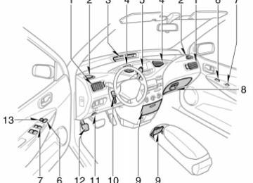
OPERATION OF INSTRUMENTS AND CONTROLS Lights, Wipers and Defogger Headlights and turn signals Emergency flasherss Instrument panel light control Interior light Personal light Windshield wipers and washer Rear window defogger
. . . . . . . . . . . . . . . . . . . . . . . . . . . . . . . . . . . . . . . . . . . . . . . . . . . . . . . . . . . . . . . . . . . . . . . . . . . . . . . . . . . . . . . . . . . . . . . . . . . . . . . . . . . . . . . . . . . . . . . . . . . . . . . . . . . . . . . . . . . . . . . . . . . . . . . . . . . . . . . . . . . . . . . . . . . . . . . . . . . . . . . . . . . . . . . . . . . . . . . . . . . . . . . . . . . . . . . . . . . . . . . . . . . . . . . . . . . . . . . . . . . . . . . . . . . . . . . . . . . . . . . . . . . . . . . . . . .
82
83
84
84
85
85
8681
The lights automatically turn off when the driver’s door is opened with the ignition turned off. To turn them on again, turn the key to the “ON” position or actuate the headlight switch. If you are going to park for over one week, make sure the head- light switch is off. When the headlight switch is turned to the first or second clickstop, the brightness of the reduced slightly unless the instrument panel light control dial is turned fully on.
instrument cluster will be
NOTICE
To prevent the battery from being dis- charged, do not leave the lights on longer than necessary when the hy- brid system is not running.
Daytime running light system The headlights turn on at reduced intensi- ty when the parking brake is released with the hybrid system started, even with the light switch in the ”OFF” position. They will not go off until the ignition switch is turned off. To turn on the other exterior lights and instrument panel lights, twist the knob to the position 1. Twist the knob to the position 2 to turn the headlights to full intensity for driving at night.
Headlights and turn signals
23p001a
tail,
license plate,
HEADLIGHTS To turn on the following lights: Twist the headlight/turn signal lever knob. Position 1—Parking, side marker and instrument panel lights Position 2—Headlights and all of above Vehicles sold in U.S.A.: When the head- lights are on, the headlight indicator lights up in the instrument cluster. Vehicles sold in Canada: When the tail lights are on, the tail light indicator lights up in the instrument cluster.
the
82
Emergency flashers
23p003a
23p004a
23p005
High–Low beams—For high beams, turn the headlights on and push the lever away from you (position 1). Pull the lever to- ward you (position 2) for low beams. The headlight high beam light indicator (blue light) on the instrument panel will tell you that the high beams are on. Flashing the high beam headlights (position 3)—Pull the way back. The high beam headlights turn off when you release the lever. You can flash the high beam headlights even with the knob turned to “OFF”.
the lever all
TURN SIGNALS To signal a turn, push the headlight/ turn signal lever up or down to position 1. The key must be in the “ON” position. The lever automatically returns after you make a turn, but you may have to return it by hand after you change lanes. To signal a lane change, move the lever up or down to the pressure point (position 2) and hold it. If the turn signal indicator lights (green lights) on the instrument panel flash faster than normal, a front or rear turn signal bulb is burned out. See “Replacing light bulbs—” on page 225 in Section 8–3.
flashers,
turn on
the emergency
To push the switch. All the turn signal lights will flash. To turn them off, push the switch once again. Turn on the emergency flashers to warn other drivers if your vehicle must be stopped where it might be a traffic hazard. Always pull as far off the road as pos- sible. The turn signal light switch will not work when the emergency flashers are operat- ing.
83
NOTICE
To prevent the battery from being dis- charged, do not leave the switch on longer than necessary when the hy- brid system is not running.
Instrument panel light control
Interior light
23p006c
23p007c
To adjust the brightness of the instru- ment panel lights, turn the dial. When the headlight switch is turned to the first or second clickstop, the brightness of the reduced slightly unless the instrument panel light control dial is turned fully on.
instrument cluster will be
To turn on the interior light, slide the switch. The interior light switch has the following positions: ”ON”—Keeps the light on all the time. ”OFF”—Turns the light off. ”DOOR”—Turns the light on when any of the door is opened. The light remains on for 15 seconds when all the doors are closed. ILLUMINATED ENTRY SYSTEM With the switch in “DOOR” position, the light comes on when either door is opened. After all the doors are closed, the light remains on for about 15 seconds and then fades out.
84
However, in the following cases, the light goes off immediately. (cid:1) All the doors are closed when the igni- tion key is in “ACC” or “ON” position.
(cid:1) All the doors are closed and locked. When all the doors are unlocked with a key or wireless remote control simulta- neously, the light comes on for about 15
seconds and then fade out, even if the door is not opened.Personal light
Windshield wipers and washer
23P012b
23p008b
To turn on the personal light, push the switch. To turn it off, push the switch again.
To turn on the windshield wipers, move the lever to the desired setting. The key must be in the “ON” position.
Lever position
Position 1
Position 2
Position 3Speed setting Intermittent
Slow Fast
The “INT TIME” band lets you adjust the wiping time interval when the wiper lever is in the intermittent position (position 1). Twist increase the time between sweeps, and downward to decrease it.
the band upward to
85
Make sure you turn the defogger off when the window is clear. Leaving the defogger on for a long time could cause the auxilia- ry battery to discharge. The defogger is not designed for drying rain water or for melting snow.
NOTICE
When cleaning the inside of the rear window, be careful not to scratch or damage the heater wires or connec- tors.
To squirt washer fluid, pull the lever toward you and release it. If the windshield wipers are off, they will operate a couple of times after the washer squirts. For instructions on adding washer fluid, see “Adding washer fluid” on page 225 in Section 8–3. In freezing weather, warm the windshield with the defroster before using the washer. This will help prevent fluid from freezing on your windshield, which can block your vision.
the washer
NOTICE
Do not operate the wipers if the wind- shield is dry. It may scratch the glass.
Rear window defogger
23p009
To defog or defrost the rear window, push the switch. The key must be in the “ON” position. The thin heater wires on the inside of the rear window will quickly clear the surface. An indicator light will illuminate to indicate the defogger is operating. Push the switch once again to turn the defogger off. The system will automatically shut off af- ter the defogger has operated about 15
minutes.86
SECTION 2– 4
OPERATION OF INSTRUMENTS AND CONTROLS Gauges, Meters and Service reminder indicators Fuel gauge Coolant temperature indicator and warning lightt Odometer and two trip meters Switching km/h MPH button Service reminder indicators and warning buzzers
. . . . . . . . . . . . . . . . . . . . . . . . . . . . . . . . . . . . . . . . . . . . . . . . . . . . . . . . . . . . . . . . . . . . . . . . . . . . . . . . . . . . . . . . . . . . . . . . . . . . . . . . . . . . . . . . . . . . . . . . . . . . . . . . . . . . . . . . . . . . . . . . . . . .
88
89
90
91
9187
Low fuel level indicator light
24p002a
Blink
If the fuel level approaches “E” or the low fuel level indicator light blinks, fill the fuel tank as soon as possible.
Fuel gauge
24p001a
the ambient
Depending on temperature, the fuel quantity is less than 45 L (11.9
gal., 9.9 lmp. gal.) even at “F”. However, this does not affect the fuel consumption and the remaining fuel ratio indicated on the gauge. (For details, see “Fuel” on page 146 in Section 3.)the
The gauge works when ignition switch is on and indicates the approxi- mate quantity of fuel remaining in the tank. Nearly full–Indicator at “F” Nearly empty–Indicator at “E” It is a good idea to keep the tank over 1/4 full. When you refuel on the slope, the indica- tor may not show the correct level. When you refuel less than about 11.4 L (3.0 gal., 2.5 lmp. gal.), the fuel indicator may not change. After the auxiliary battery is reconnected, one segment will flash for a while.
88
Coolant temperature indicator and warning lights
Low coolant temperature indicator light in blue
24p013
24p010a
24p003b
light
At the first blinking of the light, the master warning instrument cluster comes on and the message appears on the multi–information display to remind the driver to fill fuel.
the
in
The fuel system malfunctions in the fol- lowing cases, so contact your Toyota dealer. (cid:1) All the segments blink. (cid:1) The “E” mark and the segments indi-
cating remaining fuel blink.
High coolant temperature warning light in red
The indicator and warning lights indi- cate the coolant temperature when the ignition switch is on. The hybrid sys- tem operating temperature will vary with changes in weather and hybrid system load. The red high coolant temperature warning light will come on when the ignition key is turned to the “ON” position. After a few seconds, the light will go off. If your coolant temperature is cool with the ignition switch on, the blue low cool- ant temperature indicator light comes on. If it keeps lighting on with the hybrid sys- tem fully warmed, contact your Toyota dealer as soon as possible to service the vehicle.
89
If the red high coolant temperature warn- ing light comes on, your hybrid system is too hot. If your vehicle overheats, stop your vehicle and allow the hybrid system to cool. Your vehicle may overheat during severe operating conditions, such as: (cid:1) Driving up a long hill on a hot day. (cid:1) Reducing speed or stopping after high
speed driving.
NOTICE
(cid:2) Do not remove the thermostat in the cooling system as this may cause the hybrid system to over- heat. The thermostat is designed to control the flow of coolant to keep the temperature of the hybrid sys- tem within the specified operating range.
(cid:2) Do not continue driving with an overheated hybrid system. See “If your vehicle overheats” on page 172 in Section 5.
90
Odometer and two trip meters
24p004d
to
To change the meter display, quickly push and release the button. The meter display changes in the order from the odometer to trip meter A to trip meter B, the odometer each then back time you push. To reset the trip meter A to zero, dis- play the meter A reading, then push and hold the button until the meter is set to zero. The same process can be applied for resetting the trip meter B.
This meter displays the odometer and two trip meters. 1. Odometer—Shows
total distance
the
the vehicle has been driven.
2. Two
trip meters—Show
two different distances independently driven since the last time each trip meter was set to zero. You can use one trip meter to calculate the to measure the distance on each trip. All trip meter data is cancelled if the elec- trical power source is disconnected.
fuel economy and
the other
3. Trip meter
reset button—Resets
the to zero, and also
trip meters
two change the meter display.
Switching km/h MPH button
Service reminder indicators and warning buzzers— —Instrument cluster
If the indicator or buzzer comes on ...
Do this.
If the indicator or buzzer comes on ...
Do this.
24p005b
(a)
or
If parking brake is off, stop immediately and contact Toyota dealer.
You can switch the display between km/h and MPH by pressing the button.
(Indicator and buzzer)
(b)
(Indicator and buzzer)
(c)
(d)
(e)
Fasten driver’s seat belts.
Fasten front passenger’s seat belt.
Take vehicle to Toyota dealer.
Take vehicle to Toyota dealer.
(f)
(g)
(h)
(i)
(j)
or
See multi–information display.
Drive without hard acceleration.
Stop and check.
Take vehicle to Toyota dealer. If brake system warning light is also on, stop immediately and contact Toyota dealer.
Take vehicle to Toyota dealer immediately.
91
If the indicator or buzzer comes on ...
Do this.
(k)
(l)
(m)
Close all doors.
Fill up tank.
Stop and check.
(in red)
(n) Key reminder Remove key.
buzzer
(o) Shift position
reminder buzzer
Put the selector lever . in “P” position.
92
(a) Brake System Warning Light and
Buzzer
This light comes on in the following cases when the ignition key is in the “ON” posi- tion. (cid:1) When the parking brake is applied... This light comes on for a few seconds when to the “ON” position even after the parking brake is released. (cid:1) When the brake fluid level is low...
ignition key
turned
the
is
CAUTION
It is dangerous to continue driving normally when the brake fluid level is low.
(cid:1) When the regenerative brake system
is fails...
(cid:1) When fails...
the hydraulic brake booster
If the hydraulic booster causes a problem resulting in poor braking performance, the warning light comes on and buzzer sounds continuously.
Have your vehicle checked at your Toyota dealer in the following cases: (cid:1) The light does not come on even if the parking brake is applied when the igni- tion key is in the “ON” position.
(cid:1) The light does not come on even if the ignition key is turned on with the park- ing brake released.
A warning light turning on briefly during operation does not indicate a problem.
CAUTION
If any of the following conditions oc- curs, immediately stop your vehicle at a safe place and contact your Toyota dealer. (cid:1) The
light does not turn off even after the parking brake is released while the hybrid system is running. (cid:1) The warning buzzer comes on to-
gether with the warning light.
In either case, this can indicate that the brakes may not work properly and your stopping distance will become longer. Depress the brake pedal firmly and bring the vehicle to an immediate stop.
(cid:1) The brake system warning light re- mains on together with the “ABS” warning light.
In this case, not only the anti–lock brake system will fail but also the vehicle will become extremely unsta- ble during braking.
Any of the following conditions may oc- cur, but do not indicate the malfunc- tion: (cid:1) The light may stay on for about 60
seconds after the ignition key is turned to the “ON” position. It is normal if it turns off after a while.turn on
(cid:1) Depressing the brake pedal repeatedly may light and buzzer. It is normal if the light turns off and the buzzer stops sounding after a few seconds.
the warning
(cid:1) You may hear a small sound in the engine compartment after the hybrid system is started or the brake pedal is depressed repeatedly. This is a pump pulsating sound of the brake system, and it is not a malfunction.
(b) Driver’s Seat Belt Reminder Light
and Buzzer
to
remind you
light and buzzer
This buckle up the driver’s seat belt. Once the ignition key is turned to ”ON” or ”START”, the reminder light flashes and the buzzer sounds if the driver’s seat belt is not fastened. Unless the driver fastens the belt, the light keeps on flashing and the buzzer sounds 4 to 8 seconds. (c) Front Passenger’s Seat Belt
Reminder Light
This light reminds you to buckle up the front passenger’s seat belt. Once the ignition key is turned to “ON” or “START”, the reminder light flashes if a passenger sits in the front passenger seat and does not fasten the seat belt. Unless the front passenger fastens the belt, the light stays flashing. front If passenger seat, depending on its weight and how it is placed on the seat, built–in sensors in the seat cushion may detect the pressure, causing the reminder light to come on.
is placed on
luggage
load
the
(d) Discharge Warning Light This light warns that the auxiliary battery is being discharged. If it comes on while you are driving, there is a problem somewhere in the charging system. The hybrid system will continue to oper- ate, however, until the auxiliary battery is discharged. Turn off the air conditioning, blower, radio, etc., and drive directly to the nearest Toyota dealer or repair shop.
93
(e) Malfunction Indicator Lamp This lamp comes on when the ignition key is turned to the “ON” position and goes off after the engine starts. This means that the warning light system is operating properly. If the lamp remains on or the lamp comes on while driving, first check the following: (cid:1) Empty fuel tank
If the fuel tank is empty, refuel immedi- ately.
This case is a temporary malfunction. The malfunction indicator lamp will go off after taking several driving trips. If the lamp will not go off even after several trips, contact your Toyota deal- er as soon as possible. (cid:1) There is a problem somewhere in the hybrid system or warning light system itself.
Contact your Toyota dealer as soon as possible to service the vehicle.
Emissions inspection and maintenance (I/M) programs Your vehicle may not pass a state emis- sion inspection if the malfunction indicator lamp remains on. Contact your Toyota dealer to check your vehicle’s emission control system and OBD (On–Board Diag- nostics) system before taking your vehicle for the inspection. For details, see “Emissions inspection and maintenance (I/M) programs” on page 198
in Section 7. (f) Master Warning Light ( If the master warning light comes on, the warning light for the faulty system is high- lighted or the message such as “When you park your car, make sure you shift to Park P.” and “The batteries will not charge if the shifter is in N” appears on the mul- ti–information display. (See “Service re- minder indicators and warning buzzers— —Multi–information display” on page 97
in this section or “Precautions for use” on page 12 in Section 1–2 or “Fuel gauge” on page 88 in Section 2–4 for instruc- tions.)94
the
light comes on when
(g) Output Control Warning Light ( This ignition switch is on. It goes off when the electric motor is ready to run. The warning light comes on when the hy- brid vehicle battery temperature is low or high, or the hybrid vehicle battery capacity is decreased with the selector lever at “R” during driving. If the light comes on, the power will be limited. Drive your vehicle without hard acceleration. (h) Low Engine Oil Pressure Warning
Light
This light warns that the engine oil pres- sure is too low. If it flickers or stays on while you are driving, pull off the road to a safe place and stop the engine immediately. Call a Toyota dealer or qualified repair shop for assistance. flicker when The the engine is idling or it may come on briefly after a hard stop. There is no cause for concern if it then goes out when the engine is accelerated slightly. The light may come on when the oil level is extremely is not designed to indicate low oil level, and the oil level must be checked using the level dipstick.
light may occasionally
low. It
NOTICE
Do not drive the vehicle with the warning light on—even for one block. It may ruin the engine.
(i) “ABS” Warning Light The light comes on when the ignition key is turned to the “ON” position. If the anti– lock brake system works properly, the light turns off after a few seconds. There- after if the system malfunctions, the light comes on again. When the “ABS” warning light is on (and the brake system warning light is off), the anti–lock brake system does not operate, but the brake system still operates con- ventionally. When the “ABS” warning light is on (and the brake system warning light is off), the anti–lock brake system does not operate so that the wheels could lock up during a sudden braking or braking on slippery road surfaces. the following conditions If either of indicates a malfunction occurs, this somewhere in the parts monitored by the warning light system. Contact your Toyota dealer as soon as possible so service the vehicle.
(cid:1) The light does not come on when the ignition key is turned to the “ON” posi- tion, or remains on.
(cid:1) Depressing the brake pedal repeatedly may turn on the light. It is normal if it turns off after a few seconds.
(cid:1) The light comes on while you are driv-
ing.
A warning light turning on briefly during operation does not indicate a problem.
CAUTION
If the “ABS” warning light remains on together with the brake system warn- ing light, immediately stop your ve- hicle at a safe place and contact your Toyota dealer. In this case, not only the anti–lock brake system will fail but also the vehicle will become extremely unsta- ble during braking.
Either of the following conditions may occur, but does not indicate the mal- function: (cid:1) The light may stay on for about 60
seconds after the ignition key is turned to the “ON” position. It is normal if it turns off after a while.(j) SRS Warning Light This light will come on when the igni- tion key is turned to the “ACC” or “ON” position. After about 6 seconds, the light will go off. This means the system of the airbag and front seat belt pretensioners are operating properly. The warning light system monitors the air- bag sensor assembly, front airbag sen- sors, side airbag sensors, front seat belt pretensioner assemblies, warning light, in- terconnecting wiring and power sources. If either of the following conditions occurs, this indicates a malfunction somewhere in the parts monitored by the warning light system. Contact your Toyota dealer as soon as possible to service the vehicle. (cid:1) The light does not come on when the ignition key is turn to the “ACC” or “ON” position or remains on.
(cid:1) The light comes on or flashes while
driving.
95
NOTICE
Continued driving with the light on could result in the overheating of hy- brid system.
(n) Key Reminder Buzzer This buzzer reminds you to remove the key when you open the driver’s door with the ignition key in the “ACC” or “LOCK” position. (o) Shift position reminder buzzer This buzzer will sound if the driver’s door is opened in the following conditions: (cid:1) The hybrid system is on. (cid:1) The parking brake is applied. (cid:1) The selector lever is in a position other
than “P”.
CHECKING SERVICE REMINDER INDICA- TORS (except the low fuel level indica- tor light) 1. Apply the parking brake. 2. Open one of the doors.
The open door warning come on.
light should
3. Close the door.
The open door warning light should go off.
4. Turn the ignition key to “ACC”.
The SRS warning light should come on. It goes off after about 6 seconds.
5. Turn the ignition key to “START”. At this time, all the bulbs are checked in self–diagnosis mode. All the service reminder indicators ex- cept the open door warning light and SRS warning light should come on. The “ABS” warning light goes off after a few seconds.
(k) Open Door Warning Light This light remains on until all the doors are completely closed. (l) Low Fuel Level Indicator Light This light blinks when the fuel level in the tank becomes nearly empty. Fill up the tank as soon as possible. At the first blinking of the light, the mes- sage appears on the display to remind the driver to fill fuel. Contact your Toyota dealer in the fol- lowing cases: (cid:1) All the segments blink. (cid:1) The “E” mark and the segments indi-
cating remaining fuel blink. (m) High Coolant Temperature
Warning Light
The light operates to warn that the hybrid system is almost overheating. The light will come on when the ignition key is turned to the “ON” position. After a few seconds, the light will go off. If it comes on while you are driving, stop the vehicle and check your hybrid system. For detailed instructions, see “If your ve- hicle overheats” on page 172 in Section 5.
96
There may be the case that the “ABS” warning light stays on for about 60 sec- onds after the ignition key is turned to the “ON” position. It is normal if it goes out after a while. If any service reminder indicator or warn- ing buzzer does not function as described above, have it checked by your Toyota dealer as soon as possible.
—Multi–information display
24p006b
26p033b
When you change the warning display screen to other, the small warning icon is shown at the screen.
the upper right of
If an error occurs in the system, the warning display screen appears. The warning light for the faulty system blinks for about 5 seconds and remains on until the cause of an error is removed. When you push other mode switch, the screen changes. the warning display and For details on how to remedy the system, see the de- scription on the following pages.
97
If the indicator comes on ...
Do this.
(a)
(b)
(c)
Take vehicle to Toyota dealer.
Stop and check.
Take vehicle to Toyota dealer.
(a) Power Steering System Warning
Light
the power
light comes on when This steering control system fails. If the vehicle starts moving on the decline before the ignition is turned on, turning the ignition switch to “ON” will light up this light. At this time, you may feel the steering wheel heavy. If this occurs, stop your vehicle complete- ly, turn the ignition switch to “ACC” or “LOCK” and start the hybrid system again.
CAUTION
If this light comes on, take your ve- hicle to the Toyota dealer as soon as possible. In this case, you may feel the heavy steering wheel maneuver- ing. Drive your vehicle while gripping the steering wheel firmly.
98
(b) Hybrid Vehicle Battery Warning
Light
in
the
following
light comes on
This cases. a. The hybrid vehicle battery voltage drops with the running mode selector lever left in “N” position. The system works properly if you put the running mode selector lever to “P” position and the light goes off. b. The fuel tank is completely empty. (See “Fuel gauge” in this section for instruc- tions.) c. The hybrid vehicle battery charged. If this light comes on with the “READY” light on in case of c., stop your vehicle in a safe place and contact your Toyota dealer.
is dis-
(c) Hybrid System Warning Light ( This light comes on if there is a problem in the electric motor, inverter unit, hybrid vehicle battery, etc. If this light is on, stop your vehicle in a safe place immediately and contact your Toyota dealer. Even if the hybrid system warning light comes on, you could increase the speed a little temporarily by depressing the ac- celerator pedal. Immediately pull up your vehicle at a safe place and contact your Toyota dealer.
99
100
SECTION 2– 5
OPERATION OF INSTRUMENTS AND CONTROLS Ignition switch, Transmission and Parking brake Ignition switch with steering lock . . . . . . . . . . . . . . . . . . . . . . . . . . . . . . . . . . . . . . . . . . . . . . . . . . . . . . . . . . . . . . . . . . . . . . . . Hybrid transaxlee Parking brake . . . . . . . . . . . . . . . . . . . . . . . . . . . . . . . . . . . . . . . . . . . . . . . . . . . . . . . . . . . . . . . . . . . . . . . . . . . . . . . . . . . . . . . . . . . Cruise controls
102
103
106
107101
NOTICE
Do not leave the key in the “ACC” or “ON” position for a long time when the hybrid system is off. The auxiliary battery will discharge.
Ignition switch with steering lock
25p001b
is ready
“START”—The hybrid system to operate. Turn the key to the “START” position and hold the ignition switch at this position for about a few seconds until the “READY” light comes on and a beep sounds. (If the ambient temperature is low such as during winter conditions, it may take time until the “READY” light is on.” The key will return to the “ON” position when released. Being different from ordinary vehicles, you cannot start your vehicle with the running mode selector lever in “N” position. “ON”—The hybrid system starts to run when the accelerator pedal is depressed with the “READY” light and all accesso- ries on. 102
in
leave
the key
This is the normal driving position. “ACC”—Accessories such as the radio operate, but the hybrid system is off. If you leave your key in the “ACC” posi- tion for a while, put the running mode selector lever in “P” position. If you the “ACC” or “LOCK” position and open the driver’s door, a buzzer will remind you to remove the key. “LOCK”—The hybrid system is off and the steering wheel is locked. The key can be removed only at this position. You must push in the key to turn it from “ACC” to the “LOCK” position. The selec- tor lever must be put in the “P” position before pushing the key. Vehicles with hybrid vehicle immobiliser system–Once you remove the key, the hy- brid vehicle immobiliser system is auto- matically set. (See “Hybrid vehicle immobi- liser system” on page 20 in Section 2–1.) When starting the hybrid system, the key may seem stuck at the “LOCK” position. To free it, first be sure the key is pushed all the way in, and then rock the steering wheel slightly while turning the key gently.
Hybrid transaxle
Lock release button To prevent misshifting
Selector lever
25p002f
With the brake pedal de- pressed, shift while holding the lock release button in. (The ignition switch must be in the “ON” position.)
Shift while holding the lock release button in.
Shift normally.
Your hybrid transaxle has a shift lock sys- tem to minimize the possibility of incorrect operation. This means you can only shift out of “P” position when the brake pedal is depressed (with the ignition switch in “ON” position and the lock release button depressed). (a) Selector lever The shift position is also displayed on the instrument cluster. P: Parking, hybrid system starting and
key removal position
R: Reverse position N: Neutral position D: Normal driving position B: Engine braking position When is being used the cruise control even if you shift the selector lever to “B” position, engine braking will not be applied because is not can- celled. For ways to decrease the vehicle speed, see “Cruise control” on page 107.
the cruise control
103
25p003
25p004b
(c) Using engine braking To use engine braking, shift the selector lever to “B” position. During high speed driving, you may feel that deceleration by engine braking is smaller than that of ordinary vehicle. Do not continue normal driving with the selector lever in “B” position for a long time. This may cause decreased fuel economy. To prevent this, use “D” position for normal driving.
(b) Normal driving 1. Start the hybrid system as instructed in ”How to start the hybrid system” on page 162 in Section 4. The transmis- sion must be in ”P”.
2. With your foot holding down the brake
pedal, shift the selector lever to ”D”.
CAUTION
Never put your foot on the accelera- tor pedal while shifting.
3. Release the parking brake and brake the accelerator pedal
pedal. Depress slowly for smooth starting.
104
CAUTION
Be careful when downshifting on a slippery shifting