- 2009 Toyota Prius Owners Manuals
- Toyota Prius Owners Manuals
- 2008 Toyota Prius Owners Manuals
- Toyota Prius Owners Manuals
- 2013 Toyota Prius Owners Manuals
- Toyota Prius Owners Manuals
- 2004 Toyota Prius Owners Manuals
- Toyota Prius Owners Manuals
- 2001 Toyota Prius Owners Manuals
- Toyota Prius Owners Manuals
- 2005 Toyota Prius Owners Manuals
- Toyota Prius Owners Manuals
- 2015 Toyota Prius Owners Manuals
- Toyota Prius Owners Manuals
- 2012 Toyota Prius Owners Manuals
- Toyota Prius Owners Manuals
- 2002 Toyota Prius Owners Manuals
- Toyota Prius Owners Manuals
- 2010 Toyota Prius Owners Manuals
- Toyota Prius Owners Manuals
- 2014 Toyota Prius Owners Manuals
- Toyota Prius Owners Manuals
- 2006 Toyota Prius Owners Manuals
- Toyota Prius Owners Manuals
- 2003 Toyota Prius Owners Manuals
- Toyota Prius Owners Manuals
- 2007 Toyota Prius Owners Manuals
- Toyota Prius Owners Manuals
- 2011 Toyota Prius Owners Manuals
- Toyota Prius Owners Manuals
- Download PDF Manual
-
(steering switches)
26p112
If the player malfunctions
(p) If the player or another unit equipped with the player malfunctions, your audio system will display the following error messages. If “CD CHECK” appears on the display, it indicates that the disc is dirty, damaged or it was inserted up side down. Clean the disc or insert it correctly. If “CD ERROR” appears on the display, the following causes are possible. D There
the system.
trouble
inside
is
(o) Displaying the file information Touch the “DETAIL” switch on the fold- er list or file list screen. Up to 32 characters of album title, track, artist’s name or music genre can be dis- played. However, some information may not be displayed correctly or at all, de- pending on the recorded content.
Eject the disc.
D The inside of the player unit may be too hot due to the very high ambient temperature. Eject the disc and allow the player to cool down.
If “NO DATA DISC” appears on the dis- play, it indicates that a disc with no MP3
or WMA data has been inserted. Remove the disc from the player and insert a MP3
or WMA data disc. If the malfunction is not rectified, take your vehicle to your Toyota dealer.this switch
The switches are installed on the left side of the steering pad. “MODE” switch: Use to change the mode. If a compact disc is not inserted, the “CD” mode is skipped. When you push the switch with the audio system turned off, the audio system turns on. ” switches: Use the switches to ad- “ just the volume. Push “+” to increase the volume and “–” to decrease the volume. The volume continues to increase or de- crease while the switch is being pressed.
277
” or “
(b) When the “CD” mode is selected “ select a desired track or disc. D Push this switch briefly to select a de-
” switch: Use this switch to
sired track.
D To select a desired disc, push and hold this switch until the desired number of the disc appears and you hear a beep. (c) When the “MP3/WMA” mode is se-
lected ” or “
” switch: Use this switch to
“ select a desired file or folder. D Push this switch briefly to select a de-
sired file.
D To select a desired folder, push and hold this switch until the desired folder appears and you hear a beep.
CAUTION
Operate the switches with due care while you are driving to avoid acci- dents.
” or “
” switch: Push this switch for
(a) When the radio mode is selected “ seek tuning or to select a station. D To select a preset station, push the switch briefly. Do this again to select the next preset station.
D To seek a station, push and hold the switch until you hear a beep. Do this again to find the next station. If you push the switch on either side (“Ɲ” or “Ɯ”) during the seek mode, seeking will be canceled.
the
D To step up or down
frequency, push and hold the switch even after you hear a beep. When you release from the switch, the radio will begin seeking up or down for a station. Do this again to find the next station.
278
AUX adapter (Type 1 and Type 2 only)
28P129
inserting a mini plug into
An AUX adapter is installed in the rear console box. By the AUX adapter, you can listen to music from a portable audio device through the vehicle’s speaker system. To use the AUX adapter, switch to the AUX mode (external device mode) by pressing the AUX adapter is in use, “AUX” will appear on the display. To adjust the volume, turn the “PWR·VOL” knob. When using a portable audio device con- nected to the power outlet or cigarette lighter, noise may occur during playback. If this happens, use the power source of the portable audio device.
“DISC·AUX” button. When
If you install an audio system other than a genuine audio system, you will not be able to use the AUX adapter.
Audio system operating hints
NOTICE
To ensure correct audio system op- erations: z Be careful not to spill beverages
over the audio system.
z The use of a cellular phone inside or near the vehicle may cause a noise from the speakers of the au- dio system which you are listening to. However, this does not indicate a malfunction.
RADIO RECEPTION Usually, a problem with radio reception does not mean there is a problem with your radio—it is just the normal result of conditions outside the vehicle. For example, nearby buildings and terrain can interfere with FM reception. Power lines or telephone wires can interfere with AM signals. And of course, radio signals have a limited range. The farther you are from a station, the weaker its signal will be. conditions change constantly as your vehicle moves.
In addition,
reception
signals are
Here are some common reception prob- lems that probably do not indicate a prob- lem with your radio: FM Fading and drifting stations—Generally, the effective range of FM is about 40 km (25
miles). Once outside this range, you may notice fading and drifting, which increase with the distance from the radio transmit- ter. They are often accompanied by distor- tion. Multi−path—FM reflective, making it possible for two signals to reach your antenna at the same time. If this happens, the signals will cancel each oth- er out, causing a momentary flutter or loss of reception. Static and fluttering—These occur when signals are blocked by buildings, trees, or other large objects. Increasing the bass level may reduce static and fluttering. the FM signal you Station swapping—If are interrupted or weak- is ened, and there is another strong station nearby on the FM band, your radio may tune in the second station until the origi- nal signal can be picked up again.listening to
279
D Bumpy roads or other vibrations may
make your compact disc player skip.
D If moisture gets into your compact disc player, you may not hear any sound even though your compact disc player appears the disc from the player and wait until it dries.
to be working. Remove
CAUTION
Compact disc players use an invisible laser beam which could cause hazard- ous if directed outside the unit. Be sure to operate the player correctly.
radiation exposure
D Use only compact discs marked as shown above. The following products may not be playable on your compact disc player. Copy−protected CD CD−R (CD−Recordable) CD−RW (CD−Re−writable) CD−ROM
AM Fading—AM broadcasts are reflected by the upper atmosphere—especially at night. These reflected signals can interfere with those received directly from the radio sta- tion, causing the radio station to sound alternately strong and weak. Station interference—When a reflected sig- nal and a signal received directly from a radio station are very nearly the same frequency, interfere with each other, making it difficult to hear the broad- cast. Static—AM is easily affected by external sources of electrical noise, such as high tension power lines, lightening, or electri- cal motors. This results in static. CARING FOR YOUR COMPACT DISC PLAYER AND DISCS D The player
for use with
they can
intended 12cm (4.7 in.) discs only.
is
D Extremely high temperatures can keep your compact disc player from working. On hot days, use the air conditioning to cool the vehicle interior before you listen to a disc.
280
NOTICE
z Do not use special shaped, trans- parent/translucent, low quality or la- beled discs such as those shown in the illustrations. The use of such discs may damage the player or changer, or it may be impossible to eject the disc.
z This system is not designed for use of Dual Disc. Do not use Dual Disc because it may cause damage to the player or changer.
Special shaped discs
Low quality discs
Z17058
Transparent/translucent discs
Labeled discs
281
MP3 WMA FILES D MP3 (MPEG Audio Layer 3) and WMA (Windows Media Audio) are audio com- pression standards.
D The MP3/WMA player can play MP3
and WMA files on CD−ROM, CD−R and CD−RW discs. The unit can play disc recordings com- patible with ISO 9660 level 1 and level 2 and with the Romeo and Joliet file system.D When naming an MP3 or WMA file, add the appropriate file extension (.mp3
or .wma)D The MP3/WMA player plays back files with .mp3 or .wma file extensions as MP3 or WMA files. To prevent noise and playback errors, use the appropri- ate file extensions.
D Multi−session compatible CDs can also
be played.
D MP3 files are compatible with the ID3
Tag Ver. 1.0, Ver. 1.1, Ver. 2.2, and Ver. 2.3 formats. The unit cannot dis- play disc track title and artist name in other formats.title,
To clean a compact disc: Wipe it with a soft, lint−free cloth that has been damp- ened with water. Wipe in a straight line from the center to the edge of the disc (not in circles). Dry it with another soft, lint−free cloth. Do not use a conventional record cleaner or anti−static device.
Correct
Wrong
inserting
D Handle compact discs carefully, espe- them. cially when you are them on the edge and do not Hold them. Avoid getting fingerprints bend on them, particularly on the shiny side. D Dirt, scratches, warping, pin holes, or other disc damage could cause the player to skip or to repeat a section of a track. (To see a pin hole, hold the disc up to the light.)
D Remove discs from the compact disc player when you are not listening to them. Store them in their plastic cases away from moisture, heat, and direct sunlight.
282
D WMA files can contain a WMA tag that is used in the same way as an ID3
tag. WMA tags carry information such as track title, artist name.D The emphasis function is available only when playing MP3/WMA files recorded at 32, 44.1 and 48 kHz. (The system can play MP3 files with sampling fre- quencies of 16, 22.05, and 24 kHz. However, the emphasis function is not available for files recorded at these fre- quencies.)
D The sound quality of MP3/WMA files generally improves with higher bit rates. In order to achieve a reasonable level of sound quality, discs recorded with a bit rate of at least 128 kbps are recommended. Playable bit rates MP3 files: MPEG1 LAYER3—64 to 320 kbps MPEG2 LSF LAYER3—64 to 160 kbps WMA files: Ver. 7, 8 CBR—48 to 192 kbps Ver. 9 CBR—48 to 320 kbps
D The MP3/WMA player does not play back MP3/WMA files from discs record- er using packet write data transfer (UDF re- corded using “per−mastering” software rather than packet−write software.
format). Discs should be
D M3u playlists are not compatible with
the audio player.
D MP3i (MP3 interactive) and MP3PRO formats are not compatible with the au- dio player.
D The MP3 player
is compatible with
VBR (Variable Bit Rate).
D When playing back files recorded as VBR (Variable Bit Rate) files, the play time will not be correctly displayed if fast−forward or reverse operations are used.
D It is not possible to check folders that
do not include MP3/WMA files.
D MP3/WMA files in folders up to 8 lev- els deep can be played. However, the start of playback may be delayed when using discs containing numerous levels of folders. For this reason, we recom- mend creating discs with no more than two levels of folders.
D It is possible to play up to 192 folders
or 255 files on one disc.
001.mp3
002.wmaFolder 1
003.mp3
Folder 2
004.wma 005.mp3Folder 3
006.mp3D The play order of
the compact disc with the structure shown above is as follows: 001.mp3
002.wma . . .
006.mp3
283
CD−R and CD−RW discs D CD−R/CD−RW discs that have not been to the “finalizing process” (a subject proc ess that allows discs to be played on a conventional CD player) cannot be played.
D It may not be possible to play CD− R/CD−RW discs recorded on a music CD recorder or a personal computer because characteristics, scratches or dirt on the disc, or dirt, condensation, etc. on the lens of the unit.
disc
of
D It may not be possible to play discs recorded on a personal computer de- pending on the application settings and the environment. Record with the cor- rect format. (For details, contact the appropriate application manufacturers of the applications.)
D CD−R/CD−RW discs may be damaged to sunlight, high by direct exposure temperatures or other storage condi- tions. The unit may be unable to play some damaged discs.
D If you insert a CD−RW disc into the MP3/WMA player, playback will begin more slowly than with a conventional CD or CD−R disc.
284
D Recordings on CD−R/CD−RW cannot the DDCD (Double
be played using Density CD) system.
TERMS Packet write— This is a general term that describes the process of writing data on−demand to CD−R, etc., in the same way that data is written to floppy or hard discs. ID3 Tag— This is a method of embedding track−re- lated information in an MP3 file. This em- bedded information can include the track title, the artist’s name, the album title, the music genre, the year of production, com- ments and other data. The contents can be freely edited using software with ID3
tag editing the tags are restricted to the number of characters, the information can be viewed when the track is played back. WMA Tag— WMA files can contain a WMA tag that is used in the same way as an ID3 tag. WMA tags carry information such as track title, artist name.functions. Although
file names, with a 3 character
ISO 9660 format— This is the international standard for the formatting of CD−ROM folders and files. For the ISO 9660 format, there are two levels of regulations. Level 1: The file name is in 8.3 format (8 charac- ter file extension. File names must be composed of one−byte capital letters and numbers. The “_” symbol may also be included.) Level 2: The file name can have up to 31 charac- ters (including the separation mark “.” and file extension). Each folder must contain fewer than 8 hierarchies. m3u— Playlists created using “WINAMP” software have a playlist file extension (.m3u). MP3— MP3 is an audio compression standard determined by a working group (MPEG) of the ISO (International Standard Organiza- tion). MP3 compresses audio data to about 1/10 the size of that on convention- al discs.
WMA— WMA (Windows Media Audio) is an audio compression format developed by Micro- soft. It compresses files into a size small- er than that of MP3 files. The decoding formats for WMA files are Ver. 7, 8, and 9.
285
286
SECTION 2– 9
OPERATION OF INSTRUMENTS AND CONTROLS Air conditioning system Controls Climate remote control Instrument panel ventss Air conditioning filter
. . . . . . . . . . . . . . . . . . . . . . . . . . . . . . . . . . . . . . . . . . . . . . . . . . . . . . . . . . . . . . . . . . . . . . . . . . . . . . . . . . . . . . . . . . . . . . . . . . . . . . . . . . . . . . . . . . . . . . . . . . . . . . . . . . . . . . . . . . . . . . . . . . . . . . . . . . . . . . . . . . . . .
288
299
299
300287
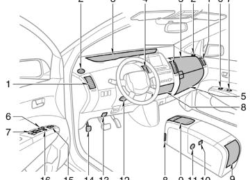
Controls
"Type 1
288
27p165a
1. Passenger
display
compartment
temperature
2. Outside temperature display
3. Temperature control switches
4. Air flow control switches
5. Fan speed control switches
6. Automatic control switch
7. Air intake control switch
8. Rear window and outside
rear view mirror defogger switch (See page 118
for details.)9. Windshield air flow switch
10. Air conditioning on−off switch
11. Air conditioning operation screen dis-
play button
12. “OFF” switch
this manual, English version screens
In are shown as an example.
"Type 2
27p164a
1. Passenger
display
compartment
temperature
2. Outside temperature display
3. Temperature control switches
4. Air flow control switches
5. Fan speed control switches
6. Automatic control switch
7. Air intake control switch
8. Rear window and outside
rear view mirror defogger switch (See page 118
for details.)9. Windshield air flow switch
10. Air conditioning on−off switch
11. “OFF” switch
12. Air conditioning operation screen dis-
play button
this manual, English version screens
In are shown as an example.
289
"Type 3
290
27p337
1. Outside temperature display
2. Passenger
display
compartment
temperature
3. Air flow control switches
4. Fan speed control switches
5. Temperature control switches
6. “OFF” switch
7. Automatic control switch
8. Rear window and outside
rear view mirror defogger switch (See page 118
for details.)9. Windshield air flow switch
10. Air intake control switch
11. Air conditioning operation screen dis-
play button
12. Air conditioning on−off switch
this manual, English version screens
In are shown as an example.
The automatic air conditioning automat- ically maintains the set temperature. features automatic This air conditioning fan speed and air flow control which auto- matically selects fan speed and air flow to control the tempera- ture. The hybrid system must be in the “IG−ON” mode. CLIMATE: Push switches controls.
to display for automatic air conditioning
the most suitable
this button
27p005a
NOTICE
To prevent the battery from being dis- charged, do not leave the air condi- tioning on than necessary when the hybrid system is not operat- ing.
longer
Air flow selection : In the beginning of the automatic air flow mode, air might be delivered.
291
When one of the manual control buttons is depressed while operating in automatic mode, the mode relevant to the depressed button is set. Other conditions continue to be adjusted automatically. However, oper- ating the air flow outlets or fan speed will turn off the automatic control. Touch the “OFF” switch to turn the air conditioning off.
in
located
indicator
instrument
SETTING OPERATION—automatic con- trol 1. Touch the “AUTO” switch. The the cluster will come on. Air conditioning is turned on if not oper- ated. Air flow quantity, switching of the diffus- ers, and switching of the air intake be- tween RECIRCULATED AIR and OUTSIDE AIR are automatically adjusted. The opera- tion status is shown by each indicator. the RECIRCULATED AIR However, mode control is changes to give priority to manual set- tings.
selected manually,
if
(a) Climate control
27p156
Type 1 and Type 2
27p111a
Type 3
292
27p157
Type 1 and Type 2
27p112a
Type 3
2. Use the “TEMP” switch to set the
desired temperature.
The temperature of air delivered to the passenger compartment will be controlled automatically according to the setting.
SETTING OPERATION—manual control When one of the manual control switches is touched while operating in automatic mode, the mode relevant to the touched switch is set. Other condi- tions continue to be adjusted automati- cally.
293
If manual air flow selection is desired—
from which air
The outlets is delivered can be selected manually by touching the switch. The function of each mode is as follows: 1. Panel—Air
flows mainly
from
the
If quick heating or cooling is desired—
27p158
instrument panel vents.
2. Bi−level—Air flows from both the floor vents and the instrument panel vents. 3. Floor—Air flows mainly from the floor
vents.
27p157
4. Floor/Windshield—Air
flows mainly floor vents and windshield
the
from vents.
Type 1 and Type 2
The selected mode is highlighted in green.
Type 1 and Type 2
27p113a
27p112a
Type 3
294Type 3
Touch the “TEMP” switches and hold ei- ther one until the maximum figure or mini- mum figure appears.
If manual fan speed control is desired—
27p159
Type 1 and Type 2
27p114a
Type 3
1. Fan speed at low 2. Fan speed at high The fan speed can be set to your desired speed by touching the appropriate air flow control switch. The higher the fan speed is, the more air is delivered. Touching the “OFF” switch turns off the fan. To remove exterior windshield frost, use the high speed setting. The selected mode is highlighted in green.
295
2−way air intake control To improve fuel economy, OUTSIDE AIR mode control changes when the air in- take selector is set in OUTSIDE AIR on the following conditions: D When the maximum heating is needed with the air flow in “Floor” or “Floor/ Windshield”, fresh air flows in the up- per compartment, while air is recircu- lated in the lower compartment. is needed, both and recirculate modes turns on.
D When cooling
fresh
in
the switch
The air intake control switch is used to switch the air intake between the OUT- SIDE AIR mode and RECIRCULATED AIR mode. With the OUTSIDE AIR mode, the system will take fresh outside air into the vehicle. If quick circulation of cooled air is de- sired, touch the air intake control switch for RECIRCULATED AIR. The indicator will come on in the instru- ment cluster while the RECIRCULATED AIR mode is selected. If recirculated air is used during heating, the windows will fog up more easily. If the hybrid system is turned off in the OUTSIDE AIR mode, the automatic control of the air intake is activated when the hybrid system is turned on again.
If manual switching of air intake is de- sired—
27p160a
Type 1 and Type 2
27p115a
Type 3
296to turn
the “A/C” switch
If manual on−off of the air conditioning is desired— the air Touch conditioning on and touch it again to turn the air conditioning off. If the system is used for ventilation, heat- ing in dry weather or removing frost or exterior fog on the windshield, turn the air conditioning off once it is no longer re- quired. This will fuel economy. The air conditioning can be used for year− round automatic in- cluding cooling and dehumidifying opera- tion.
temperature control
improve
(b) Windshield defogging and defrosting
27p161
Type 1 and Type 2
27p116a
Type 3
interior fog on the wind-
To remove shield— Touch the windshield air flow switch. To remove frost or exterior fog on the windshield— 1. Touch the upper side of the tempera- ture control switch until maximum fig- ure appears on the temperature dis- play.
2. Touch the windshield air flow switch. 3. Push the “HI” of the air flow control
switch to obtain a maximum air flow.
4. Leave the air conditioning on−off button
the windshield air
off. When flow switch is touched, the air conditioning is set to op- erate and the OUTSIDE AIR mode is set. If you touch the windshield air flow switch once again while in the windshield air flow mode, the mode then returns to the last mode used. The indicator will come on in the instru- ment cluster while the windshield air flow mode is on.
297
CAUTION
Do not use the windshield air flow switch during cooled air operation in extremely humid weather. The differ- ence between the temperature of the outside air and that of the windshield could cause the outer surface of the windshield to fog up blocking your vision.
(c) Operating tips
27p126
D The light sensor is located on the driv- er’s side edge of the instrument panel. If you put anything on this area or cover function may be adversely affected.
the sensor
the area,
D To cool off your Toyota after
it has been parked in the hot sun, drive with the windows open for a few minutes. This vents the hot air, allowing the air conditioning to cool the interior more quickly.
D Make sure the air intake grilles in front of the windshield are not blocked (by leaves or snow, for example).
298
D On humid days, do not blow cold air on the windshield. The windshield could fog up because of the difference in air temperature on the inside and outside of the windshield.
D Keep the area under the front seats clear to allow air to circulate through- out the vehicle.
for a minute
D On cold days, set the fan speed to high the intake ducts of snow or moisture. This can reduce the amount of fogging on the windows.
to help clear
D When driving on dusty roads, close all windows. If dust thrown up by the ve- hicle is still drawn into the vehicle after closing the windows, it is recommended that the air intake selector be set to OUTSIDE AIR and the fan speed se- lector to any setting except “OFF”.
D If following another vehicle on a dusty in windy and dusty road, or driving conditions, it is recommended that the air intake selector be temporarily set to RECIRCULATE, which will close off the outside passage and prevent outside air and dust from entering the vehicle interior.
Climate remote control (steering switches)
Instrument panel vents
27p104
The switches are installed on both sides of the steering pad. “A/C AUTO” switch: Use this switch to turn on the automatic mode. (For details, see page 292.) Pressing this switch in the automatic control turns the blower off. “ TEMP ” switch: Use this switch to set the desired temperature. (For details, see page 293.) “ the air page 296.) ” switch: Use this switch to remove “ interior fog on the windshield. (For details, see page 297.)
” switch: Use this switch to change intake mode. (For details, see
“ ” switch: Use this switch to turn on or off the rear window and outside rear view mirror defoggers. (For details, see page 118.)
CAUTION
Operate the switches with due care while you are driving to avoid acci- dents.
27p006a
If air flow control is not satisfactory, check the instrument panel vents. The instrument panel vents may be opened or closed as shown.
299
Air conditioning filter—
82p109
82p006b
The air conditioning filter information label is placed on the left side of the glove box as shown and indicates that a filter has been installed. The air conditioning filter prevents dust from entering the vehicle through the air conditioning vent.
The air conditioning filter is set behind the glove box.
—Checking and replacing the air conditioning filter The air conditioning filter may clog af- ter long use. The filter may need to be replaced if the air flow of the air condi- tioning and heater experiences extreme reductions in operating efficiency, or if the windows begin to fog up easily. To maintain the air conditioning efficiency, inspect and replace the air conditioning filter according to the maintenance sched- ule. In dusty areas or areas with heavy traffic flow, such as inner city or desert areas, early replacement may be required. (For scheduled maintenance information, please refer to the “Owner’s Manual Sup- plement/Scheduled Maintenance”.)
300
82p007a
82p107
82p008c
1. Open the glove box, and slide off
the damper as shown.
2. Push in each side of the glove box
to disconnect the claws.
3. Pull the filter case toward you to
take it out.
301
82p009b
4. Remove the filter from the filter case
and replace it with a new one.
5. Install the filter and filter case in the
reverse order of removal.
When setting the filter to the filter case, ensure that the flat side of the filter is down and the ribbed side is up. Position the filter case so that the “yUP” mark is pointing up and install it in the vehicle.
INFORMATION
The air filter should be installed prop- erly in position. The use of air condi- tioning with filter removed may cause deteriorated dustproof per- formance and then affect air condi- tioning performance.
the air
302
SECTION 2– 10
OPERATION OF INSTRUMENTS AND CONTROLS Other equipment Clock Rear view monitor system Power outlets Rear console box Glove boxes Garage door opener Auxiliary boxes Cup holders Bottle holders Tie−down hooks Luggage storage box Luggage cover Floor mat
. . . . . . . . . . . . . . . . . . . . . . . . . . . . . . . . . . . . . . . . . . . . . . . . . . . . . . . . . . . . . . . . . . . . . . . . . . . . . . . . . . . . . . . . . . . . . . . . . . . . . . . . . . . . . . . . . . . . . . . . . . . . . . . . . . . . . . . . . . . . . . . . . . . . . . . . . . . . . . . . . . . . . . . . . . . . . . . . . . . . . . . . . . . . . . . . . . . . . . . . . . . . . . . . . . . . . . . . . . . . . . . . . . . . . . . . . . . . . . . . . . . . . . . . . . . . . . . . . . . . . . . . . . . . . . . . . . . . . . . . . . . . . . . . . . . . . . . . . . . . . . . . . . . . . . . . . . . . . . . . . . . . . . . . . . . . . . . . . . . . . . . . . . . . . . . . . . . . . . . . . . . . . . . . . . . . . . . . . . . . . . . . . . . . . . . . . . . . . . . . . . . . . . . . . . . . . . . . . . . . . . . . . . . . . . . . . . . . . . . . . . . . . . . . . . . . . . . . . . . . . . . . . . . . . . . . . . . . . . . . . . . . . . . . . . . . . . . . . . . . . . . . . . . . . . . . . . . . . . . . . . . . . . . . . . . . . . . . . . . . . . . . . . . . . . . . . . . . . . . . . . . . . . . . . . . . . . . . . . . . . .
304
304
307
308
308
309
313
314
314
315
315
316
317303
Rear view monitor system The rear view monitor system assists the driver by displaying an image of the view behind the vehicle while back- ing up. The image is displayed in re- verse on the screen. This allows the image to appear in the same manner as that of the rear view mirror. To display the rear view image on the screen, place the selector lever in the “R” position when the “IG−ON” mode is enabled. If you move the selector lever out of the “R” position, the previous screen. Operating another func- tion of the navigation system will display another screen. The rear view monitor system is a supple- ment device intended to assist back up. When backing up, be sure to check be- hind and all around the vehicle visually.
the screen returns
to
Clock
28p009d
The digital clock indicates the time. The hybrid system must be in “ACC” or “IG−ON”. To set the hour: Push the “H” button. To set the minutes: Push the “M” button. If the electrical power source has been disconnected from the clock, the time dis- play will automatically be set to 1:00. When lights are turned on, the brightness of the time indi- cator will be reduced.
instrument panel
the
304
CAUTION
the
D Never depend on
rear view monitor system entirely when back- ing up. Always make sure your in- tended path is clear. Use caution just as you would when backing up any vehicle.
image on
D Never back up while looking only at the screen. The the screen is different from actual con- ditions. Depicted distances between objects and flat surfaces will differ from actual distances. If you back up while looking only at the screen, you may hit a vehicle, a person or an object. When backing up, be sure to check behind and all around the vehicle visually and with mir- rors before proceeding.
D Do not use the system when the back door is not completely closed.
When replacing the tires, please consult your Toyota dealer. If you replace the tires, the area displayed on the screen may change.
D If the back of the vehicle is hit, the position and mounting angle of the camera may change. Be sure to have the camera’s position and mounting angle checked at your Toyota dealer.
D If the temperature changes rapidly, such as when hot water is poured on the vehicle in cold weather, the system may not operate normally.
D If the camera lens becomes dirty, it If cannot transmit a clear water droplets, snow, or mud ad- heres to the lens, rinse with water and wipe with a soft cloth. If the lens is extremely dirty, wash it with a mild cleanser and rinse.
image.
D Use your own eyes to confirm the vehicle’s surroundings, as the dis- played image may become faint or dark, and moving images will be distorted, or not entirely visible when is low. When backing up, be sure to check behind and all around the ve- hicle visually and with mirror before proceeding.
the outside
temperature
28P134
On screen
Check surroundings for safety.
Corners of bumper
305
AREA DISPLAYED ON SCREEN Image is displayed approximately level on screen. D The area detected by the camera is limited. Objects which are close to either corner of the bumper or under the bumper cannot be seen on the screen.
D The area displayed on the screen may vary according to vehicle orien- tation or road conditions.
D When water droplets are adhering to the camera, or when humidity is high (for example, when it rains)
D When
foreign matter
(for example, snow or mud) adheres to the camera lens
28P135
D When the sun or the beam of head- lights is shining directly into the cam- era lens
THE REAR VIEW MONITOR SYSTEM CAMERA The rear view monitor system camera is located on the back door as shown in the illustration. The camera uses a special lens. The distance of the image that ap- pears on the screen differs from the actu- al distance. In it may become difficult to see the images on the screen, even when the system is functioning. D In the dark (for example, at night) D When the temperature near the lens is
following cases,
the
extremely high or low
306
Power outlets
28p010a
Instrument panel
28p107
Rear console box
Check surroundings for safety.
If a bright light (for example, sunlight re- flected off the vehicle body) is picked up by the camera, the smear effect* peculiar to the camera may occur. *: Smear effect—A phenomenon that oc- curs when a bright light (for example, sun- light reflected off is picked up by trans- mitted by light source appears to have a vertical streak above and below it.
the camera; when
the vehicle body)
the camera,
the
The power outlets are designed power supply for car accessories. The hybrid system must be in “ACC” or “IG−ON” for the power outlets to be used.
for
NOTICE
the
fuse
z To prevent
from being blown, do not use the electricity over the total vehicle capacity of 12V/120W.
z To prevent the battery from being discharged, do not use the power outlet longer than necessary when the hybrid system is not operating. z Close the power outlet lid when the power outlet is not in use. Inserting anything other than an appropriate plug that fits the outlet, or allowing any into the outlet may cause electrical failure or short circuits.
liquid to get
307
To open the glove boxes, push each button. The inside of the upper glove box is sepa- rated by the partition. When storing a lon- ger object, remove the partition. With the instrument panel lights on, the lower glove box light will come on when the lower glove box is open.
CAUTION
To reduce the chance of in case of an accident or a sudden stop, always keep the glove box doors closed while driving.
injury
Rear console box
Glove boxes
28p002a
To use the rear console box, open as shown in the illustration.
Upper glove box
CAUTION
When opening the rear console box, take due care not to catch your fin- gers.
308
28p105
Lower glove box
Garage door opener
Indicator light
28p128
Buttons
The garage door opener (HomeLinkR Universal Transceiver) is manufactured under license from HomeLinkR and can be programmed to operate garage doors, gates, entry doors, door locks, home lighting systems, and security systems, etc.
into
transmitter prior
(a) Programing the HomeLinkR The HomeLinkR in your vehicle has 3
buttons and you can store one program for each button. To ensure correct programing the HomeLinkR, install a new battery in the hand−held to program- ming. The battery side of the hand−held trans- mitter must be pointed away the HomeLinkR during the programming pro- cess. For Canadian users, follow the procedure “Programming an entrance gate/Pro- in gramming all devices the Canadian market”.from
in
the
first
to program
time, erase
When the programming the HomeLinkR for the HomeLinkR the memory once before following the steps the HomeLinkR. (See below entire HomeLinkR “(c) Erasing memory” on page 312. When carrying out (c), do not hold the buttons for longer than 30 seconds.) When registering the second and third sig- nals, simply follow the steps listed below. the HomeLinkR memory If you erase again, any signals registered previously will be erased. 1. Decide which of 3 HomeLinkR buttons
you want to program.
309
28p130a
HomeLinkR
25 to 75 mm (1 to 3 in.)
28p131
28p132
Hand−held garage transmitter
2. Place your hand−held garage transmit- ter 25 to 75 mm (1 to 3 in.) away from the surface of the HomeLinkR.
the
Keep HomeLinkR in view while programming.
light on
indicator
red
the
310
3. Simultaneously press and hold
the hand−held garage transmitter button along with the selected HomeLinkR but- ton.
Do not release the buttons until step 4
has been completed. 4. Whenthe HomeLinkR changes from a slow to a rapid flash, you can release both but- tons.
light on
indicator
the
5. Test the operation of the HomeLinkR by pressing the newly programmed button. If programming a garage door opener, check to see if the garage door opens and closes.
If the garage door does not operate, iden- tify if your garage transmitter is of the “Rolling Code” type. Press and hold the programmed HomeLinkR button. The ga- rage door has the rolling code feature if the HomeLinkR) the flashes rapidly and then remains lit after 2 seconds. If your garage transmitter is the “Rolling Code” type, proceed to the heading “Programming a rolling code sys- tem”.
indicator
light
(on
6. Repeat steps 2 through 5 for each re- maining HomeLinkR button to program another device.
it
is
to
is necessary
Programming a rolling code system “Rolling Code” If your device equipped, follow steps 1 through 4 under the heading “Programming the HomeLinkR” before proceeding with the steps listed below. 1. Locate the “training” button on the ceil- ing mounted garage door opener motor. The exact the button may vary by brand of garage door opener. Refer the owner’s guide supplied by the garage door opener manufacturer for the location of this “training” button.
location and color of
to
2. Press the “training” button on the ceil- ing mounted garage door opener motor. Following this step, you have 30 seconds in which to initiate step 3 below. 3. Press and release the vehicle’s pro- grammed HomeLinkR button twice. The garage door may open. the door does open, the programming process is complete. If the door does not open, press and release the button a third time. This third press and release will complete the programming process by opening the garage door.
If
now
should
recognize
The ceiling mounted garage door opener motor the HomeLinkR unit and be able activate the garage door up/down. 4. Repeat steps 1 through 3 each remain- to program
ing HomeLinkR button another rolling code system.
Programming an entrance gate/Program- ming all devices in the Canadian market 1. Decide which of the 3 HomeLinkR but-
2. Place
your
tons you want to program. hand−held
gate/device transmitter 25 to 75 mm (1 to 3 in.) away the HomeLinkR.
surface
from
the
of
Keep the indicator light on the HomeLinkR in view while programming. 3. Press
selected
hold
and
the
HomeLinkR button.
4. Continuously press and release (cycle) transmitter the hand−held gate/device button every two seconds until step 5
is complete. thethe HomeLinkR changes from a slow to a rapid flash, you can release both but- tons.
light on
5. When
indicator
6. Test the operation of the HomeLinkR by pressing the newly programmed button. Check to see if the gate/device oper- ates correctly.
7. Repeat steps 1 through 6 for each re- maining HomeLinkR button to program another device.
Programming other devices To program other devices such as home security systems, home door locks or lighting, contact your authorized Toyota dealer for assistance. Reprogramming a button Individual HomeLinkR buttons cannot be erased, however, to reprogram a single button, follow the procedure “Programming the HomeLinkR”. (b) Operating the HomeLinkR To operate the HomeLinkR, press the ap- propriate HomeLinkR button to activate the programmed device. The HomeLinkR indi- cator The HomeLinkR continues to send the signal for up to 20 seconds as long as the but- ton is pressed.
should
come
light
on.
311
received,
This device complies with Part 15 of the FCC Rules and with RSS−210 of the IC Rules. Operation is subject to the fol- lowing two conditions: (1) This device may not cause harmful interference, and (2) this device must accept any interfer- ence interference that may cause undesired operation. WARNING: This transmitter has been tested and complies with FCC and IC Rules. Changes or modifications not expressly approved by the party re- sponsible for compliance could void the user’s authority to operate the device.
including
Refer to HomeLinkR on the internet at: WWW.HOMELINK.COM
CAUTION
D When programming the HomeLinkR Universal Transceiver, you may be operating a garage door or other device. Make sure people and ob- jects are out of the way of the ga- rage door or other device to pre- vent potential harm or damage.
D Do not use this HomeLinkR Univer- sal Transceiver with any garage door opener that lacks the safety stop and reverse feature as re- quired by federal safety standards. (This includes any garage door opener model manufactured before April 1, 1982.) A garage door open- er which cannot detect an object (signaling the door to stop and re- verse), does not meet current feder- al safety standards. Using a garage door opener without these features increases risk of serious injury or death.
28p133
(c) Erasing
the
entire HomeLinkR
memory (all three programs)
To erase all previously programmed codes at one time, press and hold down the 2
outside buttons for 20 seconds until the indicator light flashes. If you sell your vehicle, be sure to erase the HomeLinkR the programs stored memory. For additional programming assistance Universal with your Transceiver call the: D Toyota Customer Experience Center atHomeLinkR
in
1−800−331−4331 (U.S.A.)
D Toyota Canada Customer
Interaction
Centre at 1−888−869−6828 (Canada)
312
Auxiliary boxes To use the box, open the lid as shown in the following illustrations.
CAUTION
D To reduce the chance of injury in case of an accident or a sudden stop, always keep the auxiliary box closed while driving.
D Auxiliary box on the ceiling—
As this box is designed for holding a light object such as an eyeglass, do not place any heavy objects in it. Heavy objects may cause the holder to open and contents to fly out resulting in injuries.
NOTICE
Auxiliary box on the ceiling— In hot weather, inside of the vehicle ceiling becomes very hot. Do not leave anything flammable or deform- able such as a lighter, the glasses, etc. inside.
28p117
28p003a
Front ceiling
On the instrument panel
28p011c
28p111a
Front side of the console box
Left side of the luggage compartment
313
Cup holders
Bottle holders
The cup holder is designed for holding cups or drink−cans securely. To use the cup holder, open the lid.
CAUTION
D Do not place anything else other than cups or drink−cans on the cup items may be holder, as such thrown about in the compartment and possibly injure people in the vehicle during sudden braking or in an accident.
D To reduce the chance of injury in case of an accident or a sudden stop while driving, keep the cup holder closed when not in use.
D Take due care not to catch your is
the cup holder
fingers when opened.
28p109
The bottle holders are designed to hold bottles securely.
CAUTION
Do not attempt to use the holder for any other purpose for which it was intended. Inappropriately sized or shaped objects may be thrown about in the compartment and possibly in- jure people in the vehicle during a sudden braking or an accident.
28p005b
For front seats
28p006b
For rear seats
314
NOTICE
Do not put a cup or open bottle in the bottle holder because the con- tents may spill when the door opens or closes.
Tie−down hooks
Luggage storage box
22p120
28p112a
1. To open the luggage storage box, turn the knob to the “UNLOCK” position and open the lid.
To secure your luggage, use the tie− down hooks as shown above. See “—Stowing precautions” on page 344
for precautions when loading luggage.CAUTION
To avoid personal injury, keep the tie− down hooks retracted when not in use.
315
Luggage cover
28p113a
28p114
28p115
2. Hold the lid open by inserting the sup-
port rod into the slot.
To use the luggage cover, pull it out of the retractor and hook it on the an- chors.
To remove the luggage cover, lift it up.
CAUTION
To reduce the chance of in case of an accident or a sudden stop, keep the luggage storage box closed and locked while driving.
injury
CAUTION
Do not place anything on the luggage cover. Such thrown away and possibly injure people in the vehicle during sudden braking or a collision.
items may be
316
Floor mat
28p116a
28p125
28p007b
in
the
that
time, adjust
the cover so
You can stow the luggage cover in the luggage storage box luggage compartment as shown in the illustration. At that “TOP” is facing up. After removing the luggage cover, stow it the luggage storage box or place it in somewhere other the passenger compartment. This will prevent passengers from being injured in the event of a sud- den stop or accident.
than
To replace the luggage cover, adjust the cover so that “TOP” is facing upwards.
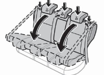
Use a floor mat of the correct size. If the vehicle carpet and floor mat have 2 holes, then they are designed for use with locking clips. Attach the floor mat to the vehicle carpet using the clips. Lock the clips the vehicle carpet.
the holes
into
in
317
28p008b
CAUTION
Make sure the floor mat is properly placed on the vehicle carpet. If the floor mat slips and interferes with the movement of the pedals during driv- ing, it may cause an accident.
318
SECTION 3
INFORMATION BEFORE DRIVING YOUR TOYOTA Information before driving your Toyota Break−in period Fuel Fuel pump shut−off system Operation in foreign countries Three−way catalytic converters Engine exhaust cautions Facts about engine oil consumption Coolant heat storage system Iridium−tipped spark plugs Brake system Electric power steering system Brake pad wear limit indicators Your Toyota’s identification Theft prevention labels Suspension and chassis Tire information Vehicle load limits Cargo and luggage Types of tires
. . . . . . . . . . . . . . . . . . . . . . . . . . . . . . . . . . . . . . . . . . . . . . . . . . . . . . . . . . . . . . . . . . . . . . . . . . . . . . . . . . . . . . . . . . . . . . . . . . . . . . . . . . . . . . . . . . . . . . . . . . . . . . . . . . . . . . . . . . . . . . . . . . . . . . . . . . . . . . . . . . . . . . . . . . . . . . . . . . . . . . . . . . . . . . . . . . . . . . . . . . . . . . . . . . . . . . . . . . . . . . . . . . . . . . . . . . . . . . . . . . . . . . . . . . . . . . . . . . . . . . . . . . . . . . . . . . . . . . . . . . . . . . . . . . . . . . . . . . . . . . . . . . . . . . . . . . . . . . . . . . . . . . . . . . . . . . . . . . . . . . . . . . . . . . . . . . . . . . . . . . . . . . . . . . . . . . . . . . . . . . . . . . . . . . . . . . . . . . . . . . . . . . . . . . . . . . . . . . . . . . . . . . . . . . . . . . . . . . . . . . . . . . . . . . . . . . . . . . . . . . . . . . . . . . . . . . . . . . . . . . . . . . . . . . . . . . . . . . . . . . . . . . . . . . . . . . . . . . . . . . . . . . . . . . . . . . . . . . . . . . . . . . . . . . . . . . . . . . . . . . . . . . . . . . . . . . . . . . . . . . . . . . . . . . . . . . . . . . . . . . . . . . . . . . . . . . . . . . . . . . . . . . . . . . . . . . . . . . . . . . . . . . . . . . . . . . . . . . . . . . . . . . . . . . . . . . . . . . . . . . . . . . . . . . . . . . . . . . . . . . . . . . . . . . . . . . . .
320
320
322
322
323
324
324
326
326
327
331
331
332
333
333
334
344
344
347319
Break−in period Drive gently and avoid high speeds. Your vehicle does not need an elaborate break−in. But following a few simple tips for the first 1000 km (600 miles) can add to the future economy and long life of your vehicle: D Avoid
full−throttle acceleration when
starting and driving.
D Avoid racing the hybrid engine. D Try to avoid hard stops during the first
300 km (200 miles).
Fuel FUEL TYPE Your vehicle must use only unleaded gasoline. To help prevent gas station mixups, your Toyota has a smaller fuel tank opening. The special nozzle on pumps with un- leaded fuel will fit it, but the larger stan- dard nozzle on pumps with leaded gas will not. At a minimum, the gasoline you use should meet the specifications of ASTM D4814 in the U.S.A. and CGSB 3.5−M93
in Canada.NOTICE
Do not use leaded gasoline. Use of leaded gasoline will cause the three−