- 2006 Ford Crown Victoria Owners Manuals
- Ford Crown Victoria Owners Manuals
- 2001 Ford Crown Victoria Owners Manuals
- Ford Crown Victoria Owners Manuals
- 2000 Ford Crown Victoria Owners Manuals
- Ford Crown Victoria Owners Manuals
- 1996 Ford Crown Victoria Owners Manuals
- Ford Crown Victoria Owners Manuals
- 1998 Ford Crown Victoria Owners Manuals
- Ford Crown Victoria Owners Manuals
- 2003 Ford Crown Victoria Owners Manuals
- Ford Crown Victoria Owners Manuals
- 2011 Ford Crown Victoria Owners Manuals
- Ford Crown Victoria Owners Manuals
- 1999 Ford Crown Victoria Owners Manuals
- Ford Crown Victoria Owners Manuals
- 2004 Ford Crown Victoria Owners Manuals
- Ford Crown Victoria Owners Manuals
- 2007 Ford Crown Victoria Owners Manuals
- Ford Crown Victoria Owners Manuals
- 2008 Ford Crown Victoria Owners Manuals
- Ford Crown Victoria Owners Manuals
- 2005 Ford Crown Victoria Owners Manuals
- Ford Crown Victoria Owners Manuals
- 2010 Ford Crown Victoria Owners Manuals
- Ford Crown Victoria Owners Manuals
- 2009 Ford Crown Victoria Owners Manuals
- Ford Crown Victoria Owners Manuals
- 2002 Ford Crown Victoria Owners Manuals
- Ford Crown Victoria Owners Manuals
- Download PDF Manual
-
drink water and induce vomiting. Get medical attention immediately.
268
File:rcsvv.ex Update:Wed Jun 28 16:02:20 1995
*[SV32400( ALL)03/95]
*[SV33100( ALL)01/95]
*[SV33200( ALL)01/95] [SV33300( GV)10/90]
one third page art:0010385-A
*[SV33700( ALL)01/95]
*[SV33750( ALL)01/95]
If the fluid is low, carefully clean and remove the cap from the reservoir. Fill the reservoir to the MAX line with Ford High Performance DOT 3 Brake Fluid C6AZ-19542-AA, C6AZ-19542-BA, or equivalent DOT 3 fluid meeting Ford specification ESA-M6C25-A.
RWARNING
If you use a brake fluid that is not DOT 3, you will cause permanent damage to your brakes.
Do not fill the reservoir above the MAX line.
The brake fluid reservoir
If you find that the fluid level is excessively low — below the seam or ridge on the outside of the plastic reservoir — have the brake system inspected.
RWARNING
Do not let the reservoir for the master cylinder run dry. This may cause the brakes to fail.
269
File:rcsvv.ex Update:Wed Jun 28 16:02:20 1995
%*[SV34800( ALL)03/95] *[SV34900( ALL)01/95]
%*[SV35000( ALL)03/95]
*[SV35100( ALL)02/95]
*[SV35200( ALL)01/95]
*[SV35300( ALL)05/95] *[SV35420( GV)11/94]
*[SV35550( GV)11/94]
[SV35650( GV)12/94]
Power Steering Fluid Check the level of the power steering fluid at least twice a year (i.e., every Spring and Fall). Checking and Adding Power Steering Fluid
1. Start the engine and let it run until the
power steering fluid reaches normal operating temperature. The power steering fluid will be at the right temperature when the engine coolant temperature gauge in the instrument cluster is near the center of the NORMAL operating temperature range.
2. While the engine idles, turn the steering
wheel back and forth several times. Make sure that the cap assembly is installed at this time.
3. Turn the engine off.
4. Check the fluid level in the power steering
fluid reservoir. The fluid level should be between the MIN and MAX lines on the side of the reservoir.
5.
If the power steering fluid is below the MIN mark, add fluid in small amounts until the level is between the MIN and MAX lines on the side of the reservoir.
6. When you are finished, put the cap assembly
back on the reservoir.
270
File:rcsvv.ex Update:Wed Jun 28 16:02:20 1995
[SV35750( GV)12/94]
half page art:0010657-C
[SV35875(M GV)03/95]
*[SV35900( ALL)01/95]
[SV36150( GV)03/93]
% [SV36280( GV)12/94]
*[SV36400( ALL)03/95]
Fluid level for power steering
Use only power steering fluid that meets Ford Specification MerconH ATF XT-2-QDX. If the power steering fluid is low, do not drive your vehicle for a long period of time before adding fluid. This can damage the power steering pump.
If you must check the power steering fluid when it is cold, make sure that the fluid reaches the MIN mark on the reservoir. Fuses, High Current Fuses, Fuse Links, and Circuit Breakers Fuses (conventional and high current) and circuit breakers protect your vehicle’s wiring system from overloading. If electrical parts in your vehicle are not working, the system may have been overloaded and blown a fuse or tripped a circuit breaker. Before you replace or repair any
271
File:rcsvv.ex Update:Wed Jun 28 16:02:20 1995
*[SV36600( ALL)03/95]
*[SV36610( ALL)01/95]
[SV37400( GV)03/93]
half page art:0011155-B
electrical parts, check the appropriate fuses (conventional and high current) or circuit breakers.
The following charts tell you which fuses or circuit breakers protect the wiring for each electrical part of your vehicle. If a fuse blows or a circuit breaker opens a circuit, all the parts of your vehicle that use that circuit will not work.
Once you have determined which fuses or circuit breakers to check, follow the procedures under Checking and replacing fuses or Checking and replacing circuit breakers in this chapter.
The instrument panel fuse panel
272
File:rcsvv.ex Update:Wed Jun 28 16:02:20 1995
%*[SV37500( ALL)02/95]
[SV38400( V)03/95]
The Instrument Panel Fuses, Circuit Breakers and Relays
thirty-two pica chart:0010395-K
273
File:rcsvv.ex Update:Wed Jun 28 16:02:20 1995
[SV38500( V)03/95]
thirty-six pica chart:0
274
File:rcsvv.ex Update:Wed Jun 28 16:02:20 1995
%*[SV39000( ALL)01/95] *[SV39200( ALL)01/95]
[SV39500( GV)06/94]
*[SV39600( ALL)05/95]
*[SV39700( ALL)05/95]
High Current Fuses
High current fuses are circuit protectors that are part of the wiring harness for some electrical equipment. These, like fuses, open when the circuit load exceeds their amperage rating. High current fuses may be purchased from your Ford or Lincoln-Mercury dealer.
The high current fuse panel is located in the engine compartment near the battery.
RWARNING
Always disconnect the battery before servicing high current fuses.
Ford recommends that high current fuses be replaced by a qualified technician.
275
File:rcsvv.ex Update:Wed Jun 28 16:02:20 1995
% [SV40100( ALL)06/93] [SV40550( V)03/94]
The high current fuse panel
full page art:0011381-A
276
File:rcsvv.ex Update:Wed Jun 28 16:02:20 1995
[SV40600( ALL)06/93]
[SV41203( V)05/95]
The high current fuses and relays
twenty-four pica chart
277
File:rcsvv.ex Update:Wed Jun 28 16:02:20 1995
[SV41204( V)05/95]
eighteen pica chart:0011382-
%*[SV41210( ALL)03/95] *[SV41215( ALL)02/95] [SV41230( GV)03/93]
[SV41245( BCGV)03/93]
[SV41550( ALL)05/92]
quarter page art:0010416-A
Checking and Replacing Fuses If you need to check a fuse, follow these steps: 1. Find the fuse panel to the left of the steering
column. Remove the fuse panel cover to expose the fuse panel.
2. Check the fuse to see if it is blown. Look through the clear side of the fuse to see if the metal wire inside is separated. If it is, the fuse should be replaced.
The side view of a fuse
278
File:rcsvv.ex Update:Wed Jun 28 16:02:20 1995
[SV41600( GV)01/93]
[SV41900( ALL)05/95]
eight pica chart:0001092-B
[SV41910(M GV)01/94]
six pica chart:0001093-B
*[SV42500( ALL)05/95]
[SV42700( GV)12/91]
*[SV42800( ALL)01/95]
3. Replace the fuse with one that has the right amperage rating. (See the following charts.)
RWARNING
Always replace a fuse with one that has the specified amperage rating. Using a fuse with a higher amperage rating can cause severe wire damage and could start a fire.
4. Replace the lower steering column finish
panel.
Even after you replace a fuse, it will continue to blow if you do not find what caused the overload. If the fuse continues to blow, have your electrical system checked.
279
File:rcsvv.ex Update:Wed Jun 28 16:02:20 1995
%*[SV42900( ALL)03/95] *[SV43000( ALL)01/95]
[SV43200( ALL)12/94]
*[SV43250( ALL)02/95]
*[SV43300( ALL)02/95]
*[SV43800(M GV)02/95]
[SV43900( GV)06/93]
[SV43950( GV)03/93]
Circuit Breakers
If you need to check a circuit breaker that is on the fuse panel, see Checking and replacing fuses in this chapter to find out how to locate the fuse panel.
Circuit breakers will reset themselves and allow the electrical parts to work again once the overload on the circuit is removed. If the circuit breakers continue to cut off electricity, have your vehicle’s electrical system checked.
Diagnostic equipment is needed to check circuit breakers. Refer to the manufacturer’s instructions.
If you replace a circuit breaker, use one with the same amperage rating. To remove a circuit breaker mounted in the fuse panel, grip it with your finger and thumb and pull it straight out of its socket.
Since the circuit breaker for the headlamps is mounted in the headlamp switch, you must replace the entire switch to install a new circuit breaker. Fuse Links
Fuse links are circuit protectors that are part of the wiring harness for some electrical equipment. These, like fuses, open when the circuit lead exceeds their amperage rating. Fuse links may be purchased from your Ford or Lincoln-Mercury dealer. See the following charts to find out which electrical parts are protected by a fuse link.
280
File:rcsvv.ex Update:Wed Jun 28 16:02:20 1995
[SV43970( GV)03/93]
ten pica chart:0010407-D
%*[SV44400( ALL)03/95] *[SV44500( ALL)01/95]
*[SV44600( ALL)01/95] *[SV44700( ALL)01/95] *[SV44800( ALL)01/95] *[SV44900( ALL)01/95] *[SV44950( ALL)02/95] *[SV45000( ALL)01/95] *[SV45100( GV)01/95] *[SV45200( ALL)01/95] %*[SV45600( ALL)01/95]
*[SV45700( ALL)01/95]
*[SV45800( ALL)01/95]
*[SV45900( ALL)01/95]
Lights and Bulb Replacement It is a good idea to check the operation of the following lights frequently:
headlamps tail lamps brakelamps hazard flasher high-mount brakelamp turn signals side markers license plate lamp
The alignment of your headlamps should be checked if:
oncoming motorists frequently signal you to turn off your vehicle’s high beams when you do not have the high beams on the headlamps do not seem to give you enough light to see clearly at night the headlamp beams are pointed substantially away from a position slightly down and to the right
281
File:rcsvv.ex Update:Wed Jun 28 16:02:20 1995
%*[SV46000( ALL)03/95] *[SV46100( ALL)01/95]
*[SV46200( ALL)05/95]
*[SV46300( ALL)01/95]
[SV46500( GV)05/95]
one third page art:0010432-B
Headlamp Bulb
The headlamps on your vehicle use replaceable bulbs. When the lamp burns out, simply replace the bulb, rather than the whole lamp.
RWARNING
Handle a halogen headlamp bulb carefully and keep out of children’s reach. Grasp the bulb only by its plastic base and do not touch the glass. The oil from your hand could cause the bulb to break the next time the headlamps are operated.
Do not remove the burned-out bulb unless you can immediately replace it with a new one. If a bulb is removed for an extended period of time, contaminants may enter the headlamp housing and affect its performance.
Headlamp bulb removal
282
File:rcsvv.ex Update:Wed Jun 28 16:02:20 1995
*[SV46600( ALL)03/95] *[SV46700( ALL)01/95]
*[SV46810( GV)01/95]
*[SV47000( GV)01/95]
*[SV47150( GV)01/95]
*[SV47400( ALL)03/95] *[SV47500( GV)01/95]
*[SV47700( GV)01/95] *[SV47900( ALL)02/95]
*[SV48050( GV)01/95] %*[SV48370( BCGV)02/95] [SV48380( BCGV)06/94]
Removing the headlamp bulb
1. Make sure that the headlamp switch is in
the OFF position.
2. Lift the hood, open access panel above
headlamp and find the bulb in the headlamp socket.
3. Remove the electrical connector by pulling
off the bulb base.
4. Remove the bulb by turning it 1/4 of a turn
to free it from the socket.
Installing the headlamp bulb
1.
Insert the glass envelope of the bulb into the socket while aligning the locking tabs.
2. Rotate the bulb 1/4 turn to lock.
3. Push the electrical connector into the rear of the plastic base until it snaps, locking it into position.
4. Close the access panel. High-Mount Brakelamp Bulbs
Your vehicle has a brakelamp mounted in the rear window, called a high-mount brakelamp. You may need to remove this lamp at times to replace the brakelamp bulb or to clean the rear window.
283
File:rcsvv.ex Update:Wed Jun 28 16:02:20 1995
[SV48700( GV)03/92]
half page art:0010436-B
% [SV48900( BCGV)06/94]
[SV49400( GV)06/94]
[SV49800( GV)10/90]
[SV50010( GV)06/94]
[SV50020( GV)06/94]
[SV50250( GV)06/94] *[SV50300( BCGV)02/95] [SV50600( GV)10/90]
[SV50900( GV)01/89]
Parts of the high-mount brakelamp
To remove the high-mount brakelamp:
1. Remove the two retaining screws with a
Phillips screwdriver.
2. Then lift the whole assembly up and over the retaining brackets. Do not move upper part of plastic attachment brackets.
3. Twist socket counterclockwise to remove
from lamp.
4. Pull bulb out of socket.
5. Replace the burned out bulbs.
To install the high-mount brakelamp:
1. Position the brakelamp over the retaining
brackets.
2.
Install and tighten the two retaining screws.
284
File:rcsvv.ex Update:Wed Jun 28 16:02:20 1995
%*[SV51600( ALL)10/92] [SV52100( V)03/95]
Using the Right Bulbs
thirty pica chart:0010442-I
285
File:rcsvv.ex Update:Wed Jun 28 16:02:20 1995
%*[SV52400( ALL)03/95] *[SV52500( ALL)05/95]
*[SV52550( ALL)05/95]
*[SV52600( ALL)05/95]
*[SV52700( ALL)01/95] *[SV52800( ALL)01/95] *[SV52900( ALL)01/95]
*[SV52950( ALL)01/95] *[SV53000( ALL)03/95]
Emission Control System Your vehicle is equipped with a catalytic converter which enables your vehicle to comply with applicable exhaust emission requirements.
RWARNING
Exhaust leaks may result in the entry of harmful and potentially lethal fumes into the passenger compartment. Under extreme conditions excessive exhaust temperatures could damage the fuel system, the interior floor covering, or other vehicle components, possibly causing a fire.
To make sure that the catalytic converter and the other emission control parts continue to work properly: q Use only unleaded fuel. q Avoid running out of fuel. q Do not turn off the ignition while your
vehicle is moving, especially at high speeds.
q Do not push start your vehicle. q Have the services listed in the Maintenance
Schedule and Record booklet performed according to the specified schedule. The scheduled maintenance services are required because they are considered essential to the life and performance of your vehicle and to its emissions system.
286
File:rcsvv.ex Update:Wed Jun 28 16:02:20 1995
*[SV53075( ALL)03/95]
*[SV53150( ALL)05/95]
*[SV53175( ALL)05/95]
*[SV53200( ALL)05/95]
*[SV53300( ALL)01/95]
In general, maintenance, replacement, or service of the emissions control devices or systems in your new Ford Motor Company vehicle or engine may be performed at your expense by any automotive repair establishment or individual using automotive parts equivalent to those which your vehicle or engine was originally equipped.
Ford strongly recommends the use of genuine Ford replacement parts. If other than Ford or Motorcraft parts or Ford authorized remanufactured parts are used for maintenance replacements or for the service of components affecting emissions control, such non-Ford parts should be equivalent to genuine Ford Motor Company parts in performance and durability. It is the owner’s responsibility to determine the equivalency of such parts. Please consult your warranty booklet for complete warranty information.
RWARNING
Do not park, idle, or drive your vehicle in dry grass or other dry ground cover. The emission system heats up the engine compartment and exhaust system, which can start a fire.
Watch for fluid leaks, strange odors, smoke, loss of oil pressure, the charge warning light, the check engine light, or the temperature warning light. These sometimes indicate that the emission system is not working properly.
Do not make any unauthorized changes to your vehicle or engine. Changes that cause more unburned fuel to reach the exhaust system can increase the temperature of the engine or exhaust system.
287
File:rcsvv.ex Update:Wed Jun 28 16:02:20 1995
*[SV53400( ALL)01/95]
*[SV53500( ALL)02/92]
*[SV53600( ALL)01/95]
%*[SV53700( ALL)02/95]
%*[SV53702( ALL)05/95]
*[SV53715( ALL)05/95]
By law, anyone who manufactures, repairs, services, sells, leases, trades vehicles, or supervises a fleet of vehicles is not permitted to intentionally remove an emission control device or prevent it from working. In some of the United States and in Canada, vehicle owners may be liable if their emission control device is removed or is prevented from working.
Never use a metal exhaust collector when you service your vehicle. If the metal collector contacts any of your vehicle’s plastic trim or bumper parts they could melt or deform.
Do not drive your vehicle if it does not operate properly. See your dealer if the engine runs on for more than five seconds after you shut it off or if it misfires, surges, stalls, or backfires.
Information about your vehicle’s emission control system is on the Vehicle Emission Control Information decal located on or near the engine. This decal identifies engine displacement and gives some tune-up specifications. Readiness for Inspection/Maintenance Testing
In some localities it may become a legal requirement to pass an Inspection/Maintenance (I/M) test of the On-Board Diagnostic (OBD) II system. If the vehicle’s powertrain system or its battery has just been serviced, the OBD II system is reset to a not ready for I/M testing condition. To prepare for I/M testing, the law specifies a “need for additional mixed city and highway driving to complete the check” of the OBD II system. As soon as all of the OBD II system checks are successfully completed, the OBD II system is set to the ready condition. The amount of driving required to reach the ready condition
288
File:rcsvv.ex Update:Wed Jun 28 16:02:20 1995
*[SV53717( ALL)05/95] [SV53730( ALL)03/95]
*[SV53735( ALL)03/95]
*[SV53740( ALL)05/95]
*[SV53745( ALL)05/95]
*[SV53747( BCGV)05/95] *[SV53752( BCGV)05/95]
*[SV53757( BCGV)05/95]
*[SV53763( BCGV)05/95]
varies with individual driving patterns. To complete this requirement in the minimum amount of time, refer to the OBD II Drive Cycle defined below. If the vehicle owner cannot or does not want to do the additional driving required by law, a service center can perform this drive cycle as it would any other type of repair work. OBD II Drive Cycle
The following steps must be run in the order shown. If steps 2 thru 9 are interrupted, repeat the preceding step. Any safe driving mode is acceptable between steps.
Always drive vehicle in safe manner according to traffic conditions and obey all traffic laws.
The engine must be warmed up and at operating temperature before proceeding with the drive modes of the following OBD II Drive Cycle.
1. Start the engine. Drive or idle (in neutral)
the vehicle for 4 minutes.
2.
Idle the vehicle in drive for 40 seconds.
3. Accelerate the vehicle to 45 mph (72 km/h)
at 1/4 to 1/2 throttle for 10 seconds.
4. Drive the vehicle with a steady throttle at
45 mph (72 km/h) for 30 seconds.
5.
Idle the vehicle in drive for 40 seconds.
289
File:rcsvv.ex Update:Wed Jun 28 16:02:20 1995
*[SV53768( BCGV)05/95]
*[SV53772( ALL)05/95]
*[SV53775( ALL)05/95]
*[SV53777( ALL)05/95]
*[SV53780( BCGV)05/95]
*[SV53784( BCGV)05/95]
*[SV53788( BCGV)05/95]
*[SV53792( BCGV)05/95]
*[SV53796( ALL)05/95]
6. Continue to drive the vehicle in city traffic at
speeds between 25 and 40 mph (40-64 km/h) for 15 minutes. During the 15
minute drive cycle the following modes must be achieved:a. at least 5 stop and idle modes at 10
seconds each
b. acceleration from idles at 1/4 to 1/2
throttle position, and
c. choose 3 different speeds to do 1.5
minute steady state throttle drives.7. Accelerate the vehicle up to between 45 and
60 mph (72-97 km/h). This should take approximately 5 minutes.
8. Drive vehicle and hold the throttle steady at
the selected speed between 45 and 60 mph (72-97 km/h) for approximately 5 minutes.
9. Drive the vehicle for 5 minutes at varying
speeds between 45 and 60 mph (72-97 km/h).
10. Bring the vehicle back to idle. Idle in drive
for 40 seconds.
11. OBD II drive cycle has been completed.
Vehicle can be turned off when convenient.
290
File:rcsvv.ex Update:Wed Jun 28 16:02:20 1995
*[SV53800( ALL)03/95]
%*[SV53900( ALL)03/95] [SV54300( GV)03/95]
twenty-two pica chart:0
*[SV54550( ALL)03/95]
Refill Capacities, Motorcraft Parts, and Lubricant Specifications Refill Capacities
NOTE: Rear axle lube quantities must be
replaced every 100,000 miles (160,000 km) or if the axle has been submerged in water. Otherwise, the lube should not be checked or changed unless a leak is suspected or repair required.
291
File:rcsvv.ex Update:Wed Jun 28 16:02:20 1995
*[SV54600( ALL)01/95] [SV54900( GV)03/94]
Motorcraft Parts
fourteen pica chart:0010453
[SV55000( ALL)09/94]
[SV55100( ALL)05/95]
[SV55125( ALL)05/95]
[SV55150( ALL)05/95]
[SV55200( ALL)03/95]
If a spark plug is removed for examination, it must be reinstalled in the same cylinder.
For 4.6L (2V) engines:
Cylinders #1, #2, #3, #4 have a PG suffix.
Cylinders #5, #6, #7, #8 have a P suffix.
If a spark plug needs to be replaced, use only spark plugs with the service number suffix letter as shown on the engine decal.
292
File:rcsvv.ex Update:Wed Jun 28 16:02:20 1995
%*[SV55300( ALL)03/95] [SV56000( GV)05/95]
Lubricant Specifications
thirty pica chart:0010586-R
*[SV56400( ALL)03/95]
NOTE: Rear axle lube quantities must be
replaced every 100,000 miles (160,000 km) or if the axle has been submerged in water. Otherwise, the lube should not be checked or changed unless a leak is suspected or repair required.
293
File:rcsvv.ex Update:Wed Jun 28 16:02:20 1995
%*[SV57000( ALL)01/95] *[SV57100( ALL)01/95] *[SV57150( ALL)01/95]
*[SV57200( ALL)01/95] *[SV57300( ALL)01/95] *[SV57400( ALL)01/95] *[SV57500( ALL)01/95]
*[SV57600( ALL)01/95] *[SV57700( ALL)01/95]
*[SV57800( ALL)01/95] *[SV57900( ALL)01/95] *[SV58000( ALL)01/95]
Vehicle Storage Maintenance Tips If you plan on storing your vehicle for an extended period of time (60 days or more), refer to the following maintenance recommendations to ensure your vehicle stays in good operating condition. General
Store all vehicles in a dry, ventilated place.
q Protect from sunlight, if possible.
If vehicles are stored outside, they require regular maintenance to protect against rust and damage.
Body q Wash vehicle thoroughly to remove dirt,
grease, oil, tar or mud from exterior surfaces, rear wheel housing and underside of front fenders.
q Periodically wash vehicles stored in exposed
locations.
q Touch-up raw or primed metal to prevent
rust.
q Cover chrome and stainless steel parts with a
thick coat of auto wax to prevent discoloration. Re-wax as necessary when the vehicle is washed.
294
File:rcsvv.ex Update:Wed Jun 28 16:02:20 1995
*[SV58100( ALL)04/95] *[SV58200( ALL)01/95] *[SV58300( ALL)01/95] %*[SV58350( ALL)01/95] *[SV58400( ALL)01/95] *[SV58500( ALL)01/95] %*[SV58600( ALL)01/95] *[SV58700( ALL)07/94]
*[SV58900( ALL)03/95]
*[SV59000( ALL)01/95]
%*[SV59200( ALL)01/95] *[SV59300( ALL)01/95]
q Lubricate all hood, door and trunk lid hinges
and latches with a light grade oil.
q Cover interior soft trim to prevent fading. q Keep all rubber parts free from oil and
solvents.
Engine
Start engine every 15 days. Run at fast idle until it reaches normal operating temperature. q With your foot on the brake, shift through all
the gears while the engine is running.
Fuel system
Fill fuel tank with high-quality unleaded fuel until the first automatic shutoff of the fuel pump nozzle.
NOTE: During extended periods of vehicle storage (60 days or more), fuel may deteriorate due to oxidation. This can damage rubber and other polymers in the fuel system and may also clog small orifices.
Ford Gas Stabilizer should be added whenever actual or expected storage periods exceed 60
days. Follow the instructions on the label. The vehicle should then be operated at idle speed to circulate the additive throughout the fuel system. Cooling system q Protect against freezing temperatures.295
File:rcsvv.ex Update:Wed Jun 28 16:02:20 1995
%*[SV59400( ALL)01/95] *[SV59500( ALL)01/95] *[SV59600( ALL)01/95] *[SV59650( ALL)03/95]
[SV59675( ALL)05/94]
%*[SV59700( ALL)01/95] *[SV59800( ALL)01/95] %*[SV59900( ALL)01/95] *[SV60000( ALL)05/95] *[SV60100( ALL)01/95] *[SV60200( ALL)01/95]
*[SV60300( ALL)03/95]
Battery q Check and recharge as necessary. q Keep connections clean and covered with a
light coat of grease. If storing your vehicle for more than 30 days without recharging the battery, it may be advisable to disconnect the battery cables to ensure battery charge is maintained for quick starting.
NOTE: If battery cables are disconnected, it
will be necessary to reset memory features.
Brakes q Make sure brakes and parking brake are fully
released.
Tires q Maintain recommended air pressure. Miscellaneous q Make sure all linkages, cables, levers and clevis pins under vehicle are covered with grease to prevent rust.
q Move vehicles at least 25 feet (8 m) every 15
days to lubricate working parts and prevent corrosion.296
File:rcsvv.ex Update:Wed Jun 28 16:02:20 1995
[SV06/95]
full page chart:FORDADPLN
297
File:rcqiv.ex Update:Fri Feb 2 11:38:47 1996
[QI03150( GV)06/95]
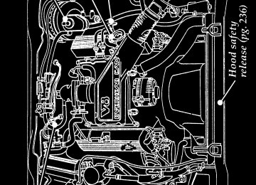
full page art:0011380-A
Label Locations
303
f
f
f
f
’
f
f
—
f
—
f
f
File:rcixv.ex Update:Fri Feb 2 11:41:03 1996
Index
ABS warning light
(see Anti-lock brake system) .
Accessory position on the ignition . Accessory power source,
power point outlet Additives, engine oil Air bag supplemental restraint system
Air cleaner filter, location . Air conditioning
description . disposal . driver air bag . indicator light operation . proper seating . tone generator . wearing safety belts.
control system .