- 2004 Volvo C70 Owners Manuals
- Volvo C70 Owners Manuals
- 2011 Volvo C70 Owners Manuals
- Volvo C70 Owners Manuals
- 1998 Volvo C70 Owners Manuals
- Volvo C70 Owners Manuals
- 2005 Volvo C70 Owners Manuals
- Volvo C70 Owners Manuals
- 2000 Volvo C70 Owners Manuals
- Volvo C70 Owners Manuals
- 2007 Volvo C70 Owners Manuals
- Volvo C70 Owners Manuals
- 2006 Volvo C70 Owners Manuals
- Volvo C70 Owners Manuals
- 2012 Volvo C70 Owners Manuals
- Volvo C70 Owners Manuals
- 2002 Volvo C70 Owners Manuals
- Volvo C70 Owners Manuals
- 2013 Volvo C70 Owners Manuals
- Volvo C70 Owners Manuals
- 2008 Volvo C70 Owners Manuals
- Volvo C70 Owners Manuals
- 2009 Volvo C70 Owners Manuals
- Volvo C70 Owners Manuals
- 1999 Volvo C70 Owners Manuals
- Volvo C70 Owners Manuals
- 2001 Volvo C70 Owners Manuals
- Volvo C70 Owners Manuals
- 2003 Volvo C70 Owners Manuals
- Volvo C70 Owners Manuals
- Download PDF Manual
-
normal. This could increase the pressure exerted on the weight sensor by a child, and could result in the airbag being enabled, which might cause it to deploy in the event of a collision, thereby injuring the child.
WARNING
Keep the following points in mind with respect to the OWS system. Failure to follow these instructions could adversely affect the system's function and result in serious injury to the occupant of the front passenger's seat:
The full weight of the front seat passenger should always be on the seat cushion. The passenger should never lift him/herself off the seat cushion using the armrest in the door or the center console, by pressing the feet on the floor, by sitting on the edge of the seat cushion, or by pressing against the backrest in a way that reduces pressure on the seat cushion. This could cause OWS to disable the passenger's side front airbag.
Do not place any type of object on the front passenger's seat in such a way that jamming, pressing, or squeezing
occurs between the object and the front seat, other than as a direct result of the correct use of the ALR/ELR seat belt (see page 32).
No objects should be placed under the front passenger's seat. This could interfere with the OWS system's function.
24 01 Safety
Side impact protection airbags
Side impact airbags (SIPS) - front seats only
As an enhancement to the structural side impact protection built into your car, the car is also equipped with Side Impact Protection System (SIPS) airbags.
The SIPS airbag system is designed to help increase occupant protection in the event of certain side impact collisions. The SIPS airbags are designed to deploy only during certain side-impact collisions, depending on the crash severity, angle, speed and point of impact.
NOTE
SIPS airbag deployment (one airbag) occurs only on the side of the vehicle affected by the impact. The airbags are not designed to deploy in all side impact situations.
Components in the SIPS airbag system This SIPS airbag system consists of gas generators and side airbag modules built into the outboard sides of both front seat backrests.
WARNING
The SIPS airbag system is a supplement to the structural Side Impact Protection System and the three-point seat belt system. It is not designed to deploy during collisions from the front or rear of the car or in rollover situations.
The use of seat covers on the front seats may impede SIPS airbag deployment. No objects, accessory equipment or stickers may be placed on, attached to or installed near the SIPS airbag system
or in the area affected by SIPS airbag deployment.
Never try to open or repair any components of the SIPS airbag system. This should be done only by a trained and
qualified Volvo service technician.
position with the seat belt properly fastened.
In order for the SIPS airbag to provide its best protection, both front seat occupants should sit in an upright
Failure to follow these instructions can result in injury to the occupants of the vehicle in the event of an accident.
25 01 Safety
Door mounted inflatable curtains
Door Mounted Inflatable Curtain system (DMIC)
The DMIC is a supplement to the structural side impact protection. These inflatable curtains are concealed in the upper section of the driver and passenger doors.
The Inflatable Curtain (DMIC) and the Side Impact Airbag System (SIPS-bag) will both deploy in certain side
impacts.
In certain situations in which there is a rollover risk, only the inflatable curtain (DMIC) may deploy.
NOTE
DMIC deployment can occur regardless of whether the power retractable hard top is up or down. If the inflatable curtain deploys, it remains inflated for approximately 5 seconds.
WARNING
The DMIC system is a supplement to the Side Impact Protection System. It is not designed to deploy during collisions from the front or rear of the vehicle. It only provides protection for the occupants of the front seats.
Never install or mount any equipment on the insides of the doors, door pillars, or side panels. This could impede
Never try to open or repair any components of the DMIC system. This should be done only by a trained and
the function of the DMIC system.
qualified Volvo service technician.
WARNING
In order for the DMIC to provide its best protection, both front seat occupants should sit in an upright position with the seat belt properly fastened; adults using the seat belt and children using the proper child restraint system. Only adults should sit in the front seats. Children must never be allowed in the front passenger seat. See page 32 for guidelines. Failure to follow these instructions can result in injury to the vehicle occupants in an accident.
26 01 Safety
Whiplash Protection System
Whiplash Protection System (WHIPS) - front seats only
The WHIPS system consists of specially designed hinges and brackets on the front seat backrests designed to help
absorb some of the energy generated in a collision from the rear (when the vehicle is "rear-ended").
In the event of a collision of this type, the hinges and brackets of the front seat backrests are designed to change position slightly to allow the backrest/head restraint to help support the occupant's head before moving slightly rearward. This movement helps absorb some of the forces that could result in whiplash.
WARNING
The WHIPS system is designed to supplement the other safety systems in your car. For this system to function
properly, the three-point seat belt must be worn. Please be aware that no system can prevent all possible injuries that may occur in an accident.
The WHIPS system is designed to function in certain collisions from the rear, depending on the crash severity,
angle and speed.
WARNING
Occupants in the front seats must never sit out of position. The occupant's back must be as upright as comfort allows and be against the seat back with the seat belt properly fastened.
27 01 Safety
Whiplash Protection System
WARNING
If your car has been involved in a rear-end collision, the front seat backrests must be inspected by a trained and
qualified Volvo service technician, even if the seats appear to be undamaged. Certain components in the WHIPS system may need to be replaced.
Do not attempt to service any component in the WHIPS system yourself.
WARNING
Boxes, suitcases, etc. wedged behind the front seats could impede the function of the WHIPS system. If the rear seat backrests are folded down, cargo must be secured to prevent it from sliding forward against the
front seat backrests in the event of a collision from the rear. This could interfere with the action of the WHIPS system.
28 01 Safety
Roll-over Protection system
Roll-over Protection system (ROPS)
The ROPS system consists of two roll bars located behind the rear seat head restraints, and a sensor that monitors the roll or pitch angle of the vehicle.
If the vehicle rolls or pitches beyond a preset angle, or in the event of a rear-end collision of sufficient force, the roll bars are automatically deployed (raised).
The ROPS system is designed to function regardless of whether the power retractable hard top is up or down. By design, the tops of the roll bars are equipped with a point in order to pierce the rear window if the top is up.
NOTE
If ROPS has deployed, the system should be inspected by a trained and qualified Volvo service technician.
WARNING
The rear seat of the Volvo C70 is intended for two occupants, and only two rear seat belts are provided. The center
section of the seat should never be used to seat a passenger.
No objects should be placed over the roll bars or behind the rear seat head restraints. All repairs or maintenance to the ROPS system should only be performed by a trained Volvo service technician.
29 01 Safety
Crash mode
Driving after a collision
If the vehicle has been involved in a collision, the text CRASH MODE SEE MANUAL may appear in the information display. This indicates that the vehicle's functionality has been reduced.
This text can only be shown if the display is undamaged and the vehicle's electrical system is intact.
CRASH MODE is a feature that is triggered if one or more of the safety systems (for example, front or side airbags, an inflatable curtain, or one or more of the seat belt tensioners) has deployed. The collision may have damaged an important function in the vehicle, such as the fuel lines, sensors for one of the safety systems, the brake system, etc.
WARNING
Never attempt to repair the vehicle yourself or to reset the electrical system after the vehicle has displayed
CRASH MODE SEE MANUAL. This could result in injury or improper system function.
Restoring the vehicle to normal operating mode should only be done by a trained and qualified Volvo service
technician.
After CRASH MODE SEE MANUAL has been displayed, if you detect the odor of fuel vapor, or see any signs of
fuel leakage, do not attempt to start the vehicle. Leave the vehicle immediately.
Attempting to start the vehicle If damage to the vehicle is minor and there is no fuel leakage, you may attempt to start the vehicle. To do so:
1. Remove the ignition key. 2. Reinsert the key in the ignition switch. The vehicle will then attempt to reset CRASH MODE to normal mode. 3. Try to start the vehicle.
Moving the vehicle If the electrical system is able to reset system status to normal (CRASH MODE SEE MANUAL will no longer be displayed), the vehicle may be moved carefully from its present position, if for example, it is blocking traffic. It should, however, not be moved farther than is absolutely necessary.
WARNING
Even if the vehicle appears to be drivable after CRASH MODE has been set, it should not be driven or towed (pulled by another vehicle). There may be concealed damage that could make it difficult or impossible to control. The vehicle should be transported on a flatbed tow truck to a trained and qualified Volvo service technician for inspection/ repairs.
30 01 Safety
Child safety
Children should be seated safely
Volvo recommends the proper use of restraint systems for all occupants including children. Remember that, regardless of age and size, a child should always be properly restrained in a car.
Your car is also equipped with ISOFIX/ LATCH attachments, which make it more convenient to install child seats.
Some restraint systems for children are designed to be secured in the vehicle by lap belts or the lap portion of a lap- shoulder belt. Such child restraint systems can help protect children in cars in the event of an accident only if they are used properly. However, children could be endangered in a crash if the child restraints are not properly secured in the vehicle. Failure to follow the installation instructions for your child restraint can result in your child striking the vehicle's interior in a sudden stop.
Holding a child in your arms is NOT a suitable substitute for a child restraint system. In an accident, a child held in a person's arms can be crushed between the vehicle's interior and an unrestrained person. The child could also be injured by striking the interior, or by being ejected from the vehicle during a sudden maneuver or impact. The same can also happen if the infant or child rides unrestrained on the seat. Other occupants should also be properly restrained to help reduce the chance of injuring or increasing the injury of a child.
All states and provinces have legislation governing how and where children should be carried in a car. Find out the regulations existing in your state or province. Recent accident statistics have shown that children are safer in rear seating positions than front seating positions when properly restrained. A child restraint system can help protect a child in a vehicle. Here's what to look for when selecting a child restraint system:
It should have a label certifying that it meets applicable Federal Motor Vehicle Safety Standards (FMVSS 213) - or
in Canada, CMVSS 213.
Make sure the child restraint system is approved for the child's height, weight and development - the label required
by the standard or regulation, or instructions for infant restraints, typically provide this information.
In using any child restraint system, we urge you to carefully look over the instructions that are provided with the restraint. Be sure you understand them and can use the device properly and safely in this vehicle. A misused child restraint system can result in increased injuries for both the infant or child and other occupants in the vehicle.
When a child has outgrown the child safety seat, you should use the rear seat with the standard seat belt fastened. The best way to help protect the child here is to place the child on a cushion so that the seat belt is properly located on the hips (see the illustration on page 39). Legislation in your state or province may mandate the use of a child seat or cushion in combination with the seat belt, depending on the child's age and/or size. Please check local regulations.
A specially designed and tested booster cushion (not available in Canada) can be obtained from your Volvo retailer for children weighing 33 - 80 lb. (15 - 36 kg) and 38-54 inches (97 - 137 cm) in height.
31 01 Safety
Child safety
WARNING
Do not use child safety seats or child booster cushions/backrests in the front passenger's seat. We also recommend
that children under 4 feet 7 inches (140 cm) in height who have outgrown these devices sit in the rear seat with the seat belt fastened.
Keep vehicle doors and trunk locked and keep keys out of a child's reach. Unsupervised children could lock
themselves in an open trunk and risk injury. Children should be taught not to play in vehicles.
On hot days, the temperature in the trunk or vehicle interior can rise very quickly. Exposure to these high
temperatures for even a short period of time can cause heat-related injury or death. Small children are particularly at
risk.
32 01 Safety
Child safety
Automatic Locking Retractor/Emergency Locking Retractor
To make child seat installation easier, each seat belt (except for the driver's belt) is equipped with a locking mechanism to help keep the seat belt taut.
When attaching the seat belt to a child seat:
Attach the seat belt to the child seat according to the child seat manufacturer's instructions. Pull the seat belt out as far as possible. Insert the seat belt latch plate into the buckle (lock) in the usual way. Release the seat belt and pull it taut around the child seat.
A sound from the seat belt retractor will be audible at this time and is normal. The belt will now be locked in place. This function is automatically disabled when the seat belt is unlocked and the belt is fully retracted.
WARNING
Do not use child safety seats or child booster cushions/backrests in the front passenger's seat. We also recommend that children who have outgrown these devices sit in the rear seat with the seat belt properly fastened.
Volvo's recommendations Why does Volvo believe that no child should sit in the front seat of a car? It's quite simple really. A front airbag is a very powerful device designed, by law, to help protect an adult.
Because of the size of the airbag and its speed of inflation, a child should never be placed in the front seat, even if he or she is properly belted or strapped into a child safety seat. Volvo has been an innovator in safety for over seventy- five years, and we'll continue to do our part. But we need your help. Please remember to put your children in the back seat, and buckle them up.
Volvo has some very specific recommendations:
Always wear your seat belt. Airbags are a SUPPLEMENTAL safety device which, when used with a three-point seat belt can help reduce
serious injuries during certain types of accidents. Volvo recommends that you do not disconnect the airbag system in your vehicle.
Volvo strongly recommends that everyone in the vehicle be properly restrained. Volvo recommends that ALL occupants (adults and children) shorter than 4 feet 7 inches (140 cm) be seated in the
back seat of any vehicle with a front passenger side airbag.
Drive safely!
33 01 Safety
Child restraint systems
Child restraints
There are three main types of child restraint systems: infant seats, convertible seats, and booster cushions. They are classified according to the child's age and size.
The following section provides general information on securing a child restraint using a three-point seat belt. Refer to page 40 for information on securing a child restraint using ISOFIX lower anchors.
WARNING
A child seat should never be used in the front passenger seat of any vehicle with a front passenger airbag - not even if the "Passenger airbag off" symbol near the rear-view mirror is illuminated (on vehicles equipped with Occupant Weight Sensor). If the severity of an accident were to cause the airbag to inflate, this could lead to serious injury or death to a child seated in this position.
WARNING
Always refer to the child restraint manufacturer's instructions for detailed information on securing the restraint.
34 01 Safety
Child restraint systems
WARNING
When not in use, keep the child restraint system secured or remove it from the passenger compartment to help
prevent it from injuring passengers in the event of a sudden stop or collision.
A small child's head represents a considerable part of its total weight and its neck is still very weak. Volvo
recommends that children up to age 4 travel, properly restrained, facing rearward. In addition, Volvo recommends that children should ride rearward facing, properly restrained, as long as possible.
35 01 Safety
Infant seats
Securing an infant seat with a seat belt
NOTE
Refer to page 40 for information on securing a child restraint using ISOFIX lower anchors.
1. Place the infant seat in the rear seat of the vehicle.
WARNING
An infant seat must be in the rear-facing position only. The infant seat should not be positioned behind the driver's seat unless there is adequate space for safe installation.
2. Attach the seat belt to the infant seat according to the manufacturer's instructions.
3. Fasten the seat belt by inserting the latch plate into the buckle (lock) until a distinct click is audible.
WARNING
A child seat should never be used in the front passenger seat of any vehicle with a front passenger airbag - not even if the "Passenger airbag off" symbol near the rear-view mirror is illuminated (on vehicles equipped with Occupant Weight Sensor). If the severity of an accident were to cause the airbag to inflate, this could lead to serious injury or death to a child seated in this position.
36 01 Safety
Infant seats
4. Pull the shoulder section of the seat belt out as far as possible to activate the belt's automatic locking function.
5. Press the infant seat firmly in place, let the seat belt retract and pull it taut. A sound from the seat belt retractor's automatic locking function will be audible at this time and is normal. The seat belt should now be locked in place.
NOTE
The locking retractor will automatically release when the seat belt is unbuckled and allowed to retract fully.
6. Push and pull the infant seat to ensure that it is held securely in place by the seat belt.
WARNING
It should not be possible to move the child restraint more than 1 in. (2.5 cm) in any direction.
The infant seat can be removed by unbuckling the seat belt and letting it retract completely.
37 01 Safety
Convertible seats
Securing a convertible seat with a seat belt
NOTE
Refer to page 40 for information on securing a child restraint using ISOFIX lower anchors.
Convertible seats can be used in either a forward or rearward-facing position, depending on the age and size of the child.
WARNING
Always use a convertible seat that is suitable for the child's age and size. See the convertible seat manufacturer's recommendations.
WARNING
A small child's head represents a considerable part of its total weight and its neck is still very weak. Volvo recommends that children up to age 4 travel, properly restrained, facing rearward. In addition, Volvo recommends that children should ride rearward facing, properly restrained, as long as possible.
1. Place the convertible seat in the rear seat of the vehicle.
2. Attach the seat belt to the convertible seat according to the manufacturer's instructions.
WARNING
Convertible child seats should be installed in the rear seat only. A rear-facing convertible seat should not be positioned behind the driver's seat unless there is adequate space for
safe installation.
38 01 Safety
Convertible seats
3. Fasten the seat belt by inserting the latch plate into the buckle (lock) until a distinct click is audible.
4. Pull the shoulder section of the seat belt out as far as possible to activate the belt's automatic locking function.
5. Press the convertible seat firmly in place, let the seat belt retract and pull it taut. A sound from the seat belt retractor's automatic locking function will be audible at this time and is normal. The seat belt should now be locked in place.
6. Push and pull the convertible seat to ensure that it is held securely in place by the seat belt.
NOTE
The locking retractor will automatically release when the seat belt is unbuckled and allowed to retract fully.
WARNING
It should not be possible to move the child restraint more than 1 in. (2.5 cm) in any direction.
The convertible seat can be removed by unbuckling the seat belt and letting it retract completely.
WARNING
A child seat should never be used in the front passenger seat of any vehicle with a front passenger airbag - not even if the "Passenger airbag off" symbol near the rear-view mirror is illuminated (on vehicles equipped with Occupant Weight Sensor). If the severity of an accident were to cause the airbag to inflate, this could lead to serious injury or death to a child seated in this position.
39 01 Safety
Booster cushions
Securing a booster cushion
Booster cushions are recommended for children who have outgrown convertible seats.
1. Place the booster cushion in the rear seat of the vehicle.
2. With the child properly seated on the booster cushion, attach the seat belt to or around the cushion according to the manufacturer's instructions.
3. Fasten the seat belt by inserting the latch plate into the buckle (lock) until a distinct click is audible.
4. Ensure that the seat belt is pulled taut and fits snugly around the child.
WARNING
The hip section of the three-point seat belt must fit snugly across the child's hips, not across the stomach. The shoulder section of the three-point seat belt should be positioned across the chest and shoulder. The shoulder belt must never be placed behind the child's back or under the arm.
40 01 Safety
ISOFIX lower anchors
Using the ISOFIX lower child seat anchors
Lower anchors for ISOFIX-equipped child seats are located in the rear, outboard seats, hidden below the backrest cushions. Symbols on the seat back upholstery mark the anchor positions (see the illustration above).
To access the anchors: 1. Put the child restraint in position.
2. Kneel on the child restraint to press down the seat cushion and locate the anchors by feel.
3. Fasten the attachment on the child restraint's lower straps to the ISOFIX lower anchors.
4. Firmly tension the lower child seat straps according to the manufacturer's instructions.
NOTE
Always follow your child seat manufacturer's installation instructions, and use both ISOFIX lower anchors and top tethers whenever possible.
WARNING
Be sure to fasten the attachment correctly to the anchor (see the illustration above). If the attachment is not
correctly fastened, the child restraint may not be properly secured in the event of a collision.
The ISOFIX lower child restraint anchors are only intended for use with child seats positioned in the left or right
seating positions.
Child seats should never be placed in the center of the rear seat. This area is not intended to be seating position
and is not equipped with a seat belt or ISOFIX anchors.
41 01 Safety
This page left intentionally blank.
Contents | Top of Page
2 0 0 7
VOLVOC70
42 02 Instruments and controls 44
Instrument overview 47
Instrument panel 50
Symbols - instrument panel 53
Information display 55
Lighting panel 57
Left-side steering wheel lever 58
Trip computer 60
Right-side steering wheel lever 62
Cruise control Right-side steering wheel keypad 64
Steering wheel adjustment, Hazard warning flashers 65
66
Parking brake 67
12-volt sockets Power windows 68
69
Mirrors 72
Personal settings HomeLink® Universal Transceiver (option) 7443 02 Instruments and controls
44 02 Instruments and controls
Instrument overview
45 02 Instruments and controls
Instrument overview
1. Steering wheel adjustment 2. Hood opener 3. Controls in driver's door (see inset illustration on the next page) 4. Left steering wheel lever 5. Lighting panel, fuel filler door opener 6. Door open handle, and locking button 7. Lock indicator light 8. Climate system air vent 9. Side window air vent 10. Cruise control 11. Horn, airbag 12. Main instrument panel 13. Audio controls 14. Right steering wheel lever 15. Ignition switch 16. Rear-view mirror 17. Seat belt reminder 18. Driver's side reading light 19. Movement detector (option), alarm sensor 20. Courtesy lighting switch 21. Position for accessory switch
65
18957
55
114
114
8162
18
47
218
60
128
69
16
98
118
9822. Passenger's side reading light 23. Display for climate control, personal settings, and audio system 24. Controls for personal settings and audio system 25. Controls for climate system 26. Hazard warning flashers 27. Door open handle, and locking button 28. Glove compartment 29. Gear selector, manual Gear selector, automatic 30. Parking brake 31. 12-volt socket 32. Switches for raising/lowering the power retractable hard top
98
72 , 218
82
65
114
101
131
132
66
67
9446 02 Instruments and controls
Instrument overview
Control panel in driver's door
68
1. All windows up/down 68
2. Power windows 71
3. Door mirror button, driver's side 4. Door mirror adjustment control 71
5. Door mirror button, passenger's side 7147 02 Instruments and controls
Instrument panel
Instrument panel
1. Speedometer
2. Turn signal, left
3. Warning symbol See the following pages for additional information.
4. Information display The display presents information and warning messages, the ambient temperature, and the clock, etc. When the ambient temperature is between 23° and 36°F (-5° and +2°C), a snowflake symbol is shown in the display. This symbol serves as a warning for possible slippery road surfaces. Please note that this symbol does not indicate a fault with your car. At low speeds, or when the car is not moving, the temperature readings may be slightly higher than the actual ambient temperature.
5. Information symbol See the next pages for additional information.
6. Turn signal, right
7. Tachometer The tachometer shows engine speed in thousands of revolutions per minute (rpm). Do not drive continuously with the needle in the red area of the dial, which indicates maximum allowable engine rpm range. Instead, shift to a higher gear or slow the vehicle down. The engine management system will automatically prevent excessively high engines speeds. This will be noticeable as a pronounced unevenness in engine speed.
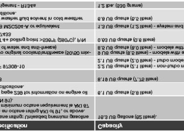
8. Indicator and warning symbols
9. Fuel gauge The fuel tank holds approximately 16.3 US gallons (62 liters). When a warning light in the gauge comes on, there are approximately 2.1
48 02 Instruments and controls
Instrument panel
US gallons (8 liters) of fuel remaining in the tank.
10. Trip odometer reset button The trip odometers are used to measure short distances. Press the button briefly to switch between the odometer for the car's total mileage and the two trip odometers, T1 and T2. A long press (more than 2 seconds) resets the currently selected trip odometer.
11. Function display This window displays information on functions such as the odometer, trip odometers, optional rain sensor, and cruise control.
12. High beam indicator
13. Clock setting button Turn the button to set the time.
14. Temperature gauge The gauge indicates the temperature of the engine cooling system. If the temperature is abnormally high and the needle enters the red zone, a message is shown in the display. Bear in mind that auxiliary lamps in front of the air intake reduce the cooling capacity at high outside temperatures and high engine loads.
15.Indicator and warning symbols
Function check
The indicator and warning symbols1 light up when you turn the ignition key to the driving position (position II) before starting. This shows that the symbols are functioning.
When the engine starts, all symbols go out. If the engine is not started within 5 seconds, all of the symbols except CHECK ENGINE and will go out. Certain symbols may not have their functions illustrated, depending on the car's equipment.
The PARK BRAKE symbol will not go out until the parking brake has been released.
Symbols in the center of the instrument panel
Warning symbol
The red warning symbol lights up to indicate a fault that could affect the car's drivability. A text explaining the nature of the fault will also be shown in the information display. The symbol and accompanying text will remain on until the fault has been corrected. This symbol may also light up in combination with other indicator or warning symbols.
1On certain engines, the symbol for low oil pressure is not used. Instead, a text warning is provided in the information display, see also page 192.
49 02 Instruments and controls
Instrument panel
If the red warning symbol lights up:
1. Stop the car as soon as possible in a suitable location.
2. Read the message in the information display.
3. Follow the instructions provided, or contact a trained and qualified Volvo service technician.
Information symbol
The yellow information symbol lights up to alert the driver to a message in the information display.
The message can be erased by pressing the READ button (see page 53), or will disappear automatically after two minutes.
This symbol may also light up in combination with other indicator or warning symbols.
NOTE
When the message "TIME FOR REGULAR SERVICE" is displayed, the text can be erased and the information symbol light can be turned off by pressing the READ button (see page 53). The text will disappear and the symbol light will go out automatically after two minutes.
50 02 Instruments and controls
Symbols - instrument panel
Symbols - left side
1. Malfunction indicator light
As you drive, a computer called On-Board Diagnostics II (OBDII) monitors your car's engine, transmission, electrical and emission systems.
The CHECK ENGINE light will light up if the computer senses a condition that potentially may need correcting. When this happens, please have your car checked by a trained and qualified Volvo service technician as soon as possible.
A CHECK ENGINE light may have many causes. Sometimes, you may not notice a change in your car's behavior. Even so, an uncorrected condition could hurt fuel economy, emission controls, and drivability. Extended driving without correcting the cause could even damage other components in your car.
NOTE
Canadian models are equipped with the second symbol.
2. Anti-lock Brake system (ABS)
If the warning light comes on, there is a malfunction of the ABS system (the standard braking system will still function).
The vehicle should be driven to a trained and qualified Volvo service technician for inspection. See page 136 for additional information.
NOTE
Canadian models are equipped with the second symbol.
3. Rear fog light
This symbol indicates that the rear fog light (located in the driver's side taillight cluster) is on.
4. Dynamic Stability and Traction Control system (DSTC)
This indicator symbol flashes when the DSTC is actively working to stabilize the car. See page 138 for more detailed information.
5. Not in use
6. Fuel level warning light
When this light comes on, there are approximately 2.1 US gallons (8 liters) of fuel remaining in the tank.
51 02 Instruments and controls
Symbols - instrument panel
Symbols - right side
1. Turn signal indicator for trailer (certain models)
If you are towing a trailer, this light will flash simultaneously with the turn signals on the trailer. If the light does not flash when signaling, one of the turn signals on the trailer or on the car are not functioning properly.
2. Parking brake applied
Parking brake applied This light is on when the parking brake (hand brake) is applied. The parking brake lever is situated between the front seats. Always pull up this lever as far as possible when applying the parking brake.
NOTE
Canadian models are equipped with the second symbol.
3. SRS warning light
If this light comes on while the car is being driven, or remains on for longer than approximately 10 seconds after the car has been started, the SRS system's diagnostic functions have detected a fault in a seat belt lock or tensioner, a front airbag, side impact airbag, and/or an inflatable curtain. Have the system(s) inspected by a trained and qualified Volvo service technician as soon as possible.
4. Oil pressure warning light1
If the light comes on while driving, stop the car, stop the engine immediately, and check the engine oil level. If the oil level is normal and the light stays on after restart, have the car towed to the nearest trained and qualified Volvo service technician. After hard driving, the light may come on occasionally when the engine is idling. This is normal, provided it goes off when the engine speed is increased.
5. Seat belt reminder
See page 16 for detailed information.
6. Generator warning light
If the light comes on while the engine is running, have the charging system checked by a trained and qualified Volvo service technician.
7. Brake failure warning light
If this light comes on while driving or braking, stop the car as quickly as possible in a safe place, open the hood, and check
1 On certain engines, this symbol is not used to indicate low oil pressure. Instead, a text warning is provided in the information display, see also page 192.
52 02 Instruments and controls
Symbols - instrument panel
the brake fluid level in the reservoir. See page 190 for the location of the reservoir.
NOTE
Canadian models are equipped with the second symbol.
WARNING
If the fluid level is below the MIN mark in the reservoir or if a "Brake failure - Service urgent" message is displayed in the information display: DO NOT DRIVE. Have the car towed to a trained and qualified Volvo service technician and have the brake system inspected.
If the fluid level is below the MIN mark in the reservoir or if a "BRAKE FAILURE - SERVICE URGENT" message is displayed in the information display: DO NOT DRIVE. Have the car towed to a trained and qualified Volvo service technician and have the brake system inspected.
If the BRAKE and ABS warning lights come on at the same time, this could indicate a fault in the brake system. In this case:
1. Stop the car in a suitable place and switch off the engine.
2. Restart the engine.
3. If both warning lights go off, no further action is required and the car can be driven.
4. If both lights remain on after the engine has been restarted, switch off the engine again and check the brake fluid level. See page 190 for the location of the reservoir.
Door open warning
The driver will be alerted if either door, the hood, or the trunk lid are open or ajar.
At low speeds
If the car is moving at a speed of less than approximately 4 m.p.h. (7 km/h), the Information symbol in the instrument panel will light up and a message will be shown in the information display indicating which door(s), etc is not completely closed.
At higher speeds
If the car is moving at a speed above approximately 4 m.p.h. (7 km/h), the Warning symbol in the instrument panel will light up and a message will be shown in the information display indicating which door(s), etc is not completely closed.
Hood and trunk
If the hood and/or trunk lid is not completely closed, the Information symbol in the instrument panel will light up and a message will be displayed, regardless of the vehicle's speed.
53 02 Instruments and controls
Information display
Messages
When an indicator or warning light in the instrument panel comes on, a message is also shown in the information display. To read a message:
1. Press the READ button (1).
2. Pressing READ repeatedly enables you to scroll to any other messages that may be stored.
NOTE
If a message is displayed when e.g. you are using the trip computer, this message must be read before you can access the trip computer
54 02 Instruments and controls
Information display
Meaning
Message STOP SAFELY Stop the car in a safe place and switch off the engine to help prevent the risk of serious damage. STOP ENGINE Stop the car in a safe place and switch off the engine to help prevent the risk of serious damage. SERVICE URGENT SEE MANUAL Refer to your owner's manual. For additional information, please contact a trained and qualified SERVICE
Volvo service technician. Take your car to a trained and qualified Volvo service technician for inspection as soon as possible
Take your car to a trained and qualified Volvo service technician for inspection immediately.
REQUIRED TIME FOR REGULAR SERVICE REMINDER CHECK OIL LEVEL DSTC SPIN CONTROL OFF
(but preferably before the next scheduled maintenance service). This message is affected by the number of miles/km driven, by the number of months, or by the number of engine hours since the service reminder was reset at the most recent regularly scheduled service.
Check the oil level when this message is displayed. See page 191.
The stability system's spin control function has been turned off. See page 138 for details.
55 02 Instruments and controls
Lighting panel
Pos.
Lighting Daytime running lights/headlights off. High beam flash only. Parking lights Daytime running lights. High beams and high beam flash can be used in this position.
Parking lights
The front and rear parking lights can be turned on even when the ignition is switched off.
Turn switch (1) to position
The license plate lights also illuminate when the parking lights are switched on.
Headlights
1. Turn the ignition key to position II.
2. The low beam headlights (daytime running lights) illuminate automatically, except when the light switch (1) is in position
1.
NOTE
See page 57 for information on switching between high and low beams.
Fog lights
Front fog lights (option) The front fog lights can be used in combination with either the headlights or the parking lights.
1. Turn the ignition to position II.
2. Press button (3) to turn on the front fog lights.
An indicator light in the button illuminates when the front fog lights are on.
Rear fog light The single rear fog light is located in the driver's side taillight cluster.
The rear fog light will only function in combination with the high/low beam headlights or the optional front fog lights.
1. Turn the ignition key to position II.
2. Press button (5) to turn on the rear fog light.
An indicator light in the button illuminates when the rear fog light is on.
NOTE
The rear fog light is considerably brighter than the normal taillights and should be used only when conditions such as fog, rain, snow, smoke or dust reduce visibility for other vehicles to less than 500 ft. (150 meters).
1On Canadian models, the daytime running lights will remain on with the light switch in this position.
56 02 Instruments and controls
Lighting panel
Instrument panel lighting
The instrument panel lighting illuminates when the ignition is in position II and the light switch (1) is in either position
or
NOTE
To make it easier to read the odometer, trip odometer, clock, and ambient temperature, these gauges illuminate when the vehicle is unlocked and when the key has been removed from the ignition switch. The lighting will go out when the vehicle is locked.
Move the thumb wheel (2) up to increase brightness or down to decrease brightness.
Unlocking the fuel filler door
With the ignition switched off, press button (4) to unlock the fuel filler door. Please note that the fuel filler door will remain unlocked until the car begins to move forward.
An audible click will be heard when the fuel filler door re-locks.
Please refer to the following information for instructions on manually opening the fuel filler door.
Manually unlocking the fuel filler door
If it should be necessary to manually unlock the fuel filler door from the trunk, the power retractable hard top should be up.
1. Remove the panel covering the taillight housing on the right side of the trunk.
2. Pull the cord that is attached to a hook to pop open the fuel filler door.
When the fuel filler door has opened, return the cord to the hook and replace the taillight cover panel.
57 02 Instruments and controls
Left-side steering wheel lever
Lever positions
1. Turn signals, lane change position
2. Turn signals, position for normal turns
3. High beam flash
4. Toggle between high and low beams, Home Safe lighting
Turn signals
When turning
Move the lever as far up or down as possible (to position 2) to start the turn signals.
The turn signals will be cancelled automatically by the movement of the steering wheel, or the lever can be returned to its initial position by hand.
When changing lanes
The driver can automatically flash the turn signals 3 times by:
Moving the turn signal lever up or down to position 1 and releasing it. Moving the lever up or down to position 2 and immediately back to its original position.
NOTE
This automatic flashing sequence can be interrupted by immediately moving the lever in the opposite direction. If the turn signal indicator flashes faster than normal, check for a burned-out turn signal bulb.
High/low beam headlights
Continuous high beams 1. Turn the ignition key to position II.
2. With the light switch (1) in position 4) to toggle between high and low beams.
High beam flash 1. Turn the ignition key to position II.
2. Pull the turn signal lever to position
, (see page 55) pull the turn signal lever toward the steering wheel (position
3. The high beams will remain on until the lever is released.
Home safe lighting When you leave your car at night, you can make use of the home safe lighting function to illuminate the area in front of the car.
1. Remove the key from the ignition switch.
2. Pull the direction indicator lever as far as possible towards the steering wheel (to position 4) and release it.
3. Exit the car and lock the doors.
The headlights and parking lights will illuminate and remain on for 301, 60 or 90 seconds. The time interval can be changed according to your preferences by using the Personal Settings function, see page 72 for more information.
1Factory setting
58 02 Instruments and controls
Trip computer
The trip computer stores information gathered from several systems in your car and has four menus (five on Canadian models) that can be shown in the information display.
MILES TO EMPTY TANK AVERAGE (average fuel consumption) INSTANTANEOUS (current fuel consumption) AVERAGE SPEED DSTC (see page 138 for detailed information.) ACTUAL SPEED (current speed in m.p.h., Canadian models only)
NOTE
Warning messages from the car's monitoring systems will override the trip computer function.
If a warning message is shown in the information display while you are using the trip computer:
1. You must acknowledge the message by pressing the READ button (A).
2. Press button A again to return to the trip computer function.
Controls
The trip computer functions can be accessed by twisting INFO (B) one step at a time in either direction. Twisting a final time returns you to the original function.
The trip computer can be reset (average fuel consumption and average speed will be erased from system memory) by pressing RESET (C) for at least five seconds.
MILES TO EMPTY TANK This function shows the approximate distance that can be driven on the fuel remaining in the tank. This calculation is based on average fuel consumption during the last 20 miles (30 km) of driving and the amount of fuel remaining in the tank when the reading was taken. When the driving distance on current fuel reserve is less than 12 miles (20 km), "---- " will be displayed in the information display.
AVERAGE This value indicates fuel consumption since the last time the trip computer was reset (by pressing RESET, button C).
When the engine is switched off, information on fuel consumption is stored and remains in system memory until the RESET (button C) is pressed again.
INSTANTANEOUS This value indicates the current fuel consumption, based on readings taken once per second. When the car is not moving, "----" will be displayed.
AVERAGE SPEED This value indicates average speed since the last time the trip computer was reset (by pressing RESET, button C). When the engine is switched off, information on average speed is stored and remains in system memory until the RESET (button C) is pressed again.
59 02 Instruments and controls
Trip computer
ACTUAL SPEED (Canadian models only) This function provides the driver with an instantaneous conversion of the car's current speed from km/h to m.p.h.
NOTE
Trip computer readings may vary slightly depending on the circumference of the tires on the car, tire inflation, or driving style.
60 02 Instruments and controls
Right-side steering wheel lever
Windshield wipers
A. Windshield/headlight washers
B. Rain sensor (option) - on/off
C. Thumb wheel
D. Not in use
Windshield wipers off
The windshield wipers are off when the lever is in position 0.
Manual wiper function
From position 0, move the lever upward. The windshield wipers will sweep one stroke at a time for as long as the lever is held up.
Intermittent wiper function
With the lever in this position, you can set the wiper interval by moving the thumb wheel (C) upward to increase wiper speed or downward to decrease the speed.
Continuous wiper function
The wipers operate at "normal" speed.
High speed wiper function.
A -Windshield washers
Pull the lever toward the steering wheel and release it. The wipers will make 2-3 sweeps across the windshield after the lever has been released.
CAUTION
Use ample washer fluid when washing the windshield. The windshield should be thoroughly wet when the wipers are in operation.
Headlight washers (certain models)
When the lever has been pulled, high pressure jets mounted in the bumper will spray the headlights.
The following applies to conserve washer fluid (see page 55 for information on the light switch positions):
Low/high beam headlights on
The headlights will be washed the first time the windshield is washed. Thereafter, the headlights will only be washed once for every five times the windshield is washed within a 10-minute period.
Parking lights on
Optional Bi-Xenon headlights will be washed once for every five times the windshield is washed. Normal halogen headlights will not be washed.
61 02 Instruments and controls
Right-side steering wheel lever
B - Rain sensor (option)
The rain sensor automatically regulates windshield wiper speed according to the amount of water on the windshield. The sensitivity of the rain sensor is adjusted by moving the thumb wheel (C in the illustration on the previous page) up (the wipers will sweep the windshield more frequently) or down (the wipers will sweep the windshield less frequently).
On/Off
To activate the rain sensor: 1. Switch on the ignition. 2. Put the windshield wiper lever in position 0. 3. Press button B (see the illustration on the previous page). The rain sensor symbol will appear in the lower display.
The rain sensor can be deactivated by:
Pressing button (B) with the ignition on.
or
Moving the windshield wiper lever down. If the lever is moved up, the rain sensor function will remain activated
CAUTION
The rain sensor should be deactivated when washing the car in an automatic car wash, etc. If the rain sensor function is left on, the wipers will start inadvertently in the car wash and could be damaged.
C - Thumb wheel
The thumb wheel is used to set the wiper interval when intermittent wiping is selected, or the sensitivity to the amount of rain on the windshield when the rain sensor is selected. Move the wheel upward or downward to increase/decrease wiper speed when the intermittent function is selected, or to increase/decrease the optional rain sensor's sensitivity when the this function is activated
62 02 Instruments and controls
Cruise control
Engaging the cruise control function
The cruise control buttons are located on the left side of the steering wheel hub.
1. Press the CRUISE button. CRUISE will appear in the function display in the center of the instrument panel.
NOTE
This does not set the vehicle's speed.
2. Press + or - to set the current speed. CRUISE ON will be displayed.
Increasing or decreasing speed
Use + or - in the following ways to increase or decrease the vehicle's speed:
1. Press and hold down + or - until the vehicle reaches the desired speed. This will become the set speed when the button is released.
2. Press + or - for approximately a half second and release the button to increase or decrease vehicle speed by approximately 1 mph (1.6 km/h).
NOTE
Cruise control will not function at speeds below 20 mph. (30 km/h).
Momentary acceleration, for less than 1 minute (e.g. when passing another car), does not affect cruise control operation. The car will automatically return to the previously set speed when the accelerator pedal is released.
63 02 Instruments and controls
Cruise control
Temporarily disengaging the cruise control
Press 0 to temporarily disengage cruise control.
CRUISE will appear in the function display. The currently set speed is stored in the system's memory.
Cruise control is also automatically disengaged:
If the speed drops below approximately 20 mph (30 km/h) when driving uphill. When the brake or clutch pedal is depressed. If the gear selector is moved to position N. During wheel spin or wheel lock-up. If the vehicle's speed is increased by using the accelerator pedal for more than 1 minute.
Returning to the set speed
Press the button to resume the previously set speed.
Disengaging cruise control
Cruise control can also be disengaged by:
Pressing the CRUISE button (CRUISE ON will no longer be shown in the function display). Putting the gear selector in Neutral (N).
WARNING
Cruise control should not be used in heavy traffic or when driving on wet or slippery roads. Cruise control may not maintain set speed on steep downgrades.
64 02 Instruments and controls
Right-side steering wheel keypad
Steering wheel keypad
The four buttons on the steering wheel keypad can be used to control the audio system.
The steering wheel keypad can be used to adjust volume, shift between preset stations and change CD tracks. Press one of the two left-hand buttons briefly to change to the next/previous preset radio station, or to go to the
next/ previous track on a CD.
Press and hold down these buttons to search within a track on a CD.
65 02 Instruments and controls
Steering wheel adjustment, Hazard warning flashers
Steering wheel adjustment
Both the height and the reach of the steering wheel can be adjusted to a comfortable position for the driver.
1. Pull down the lever on the steering column to release the steering wheel.
2. Adjust the steering wheel to a suitable position
3. Press the lever back into place to lock the steering wheel in the new position. If necessary, press the steering wheel slightly while pressing the lever into the locked position.
Check that the steering wheel is locked in the new position.
WARNING
Never adjust the steering wheel while driving.
Hazard warning flashers
The four-way flasher should be used to indicate that the vehicle has become a traffic hazard. To activate the flashers, press the triangular button in the center dash. Press the button again to turn off the flashers.
NOTE
Regulations regarding the use of the hazard warning flasher may vary, depending on where you live.
66 02 Instruments and controls
Parking brake
Parking brake (hand brake)
The parking brake lever is located between the front seats.
NOTE
The indicator light will light up even if the parking brake has only been partially applied.
When applying the parking brake
1. Press firmly on the brake pedal.
2. Pull the parking brake lever up firmly to its full extent.
3. Release the brake pedal and ensure that the vehicle is at a standstill.
4. If the vehicle rolls, the parking brake lever must be pulled more firmly.
5. When parking a vehicle always put the gear selector in first gear (for manual transmission) or P (for automatic transmission).
Parking on a hill
If the vehicle is pointing uphill, turn the front wheels so that they point away from the curb. If the vehicle is pointing downhill, turn the front wheels so that they point toward the curb.
Releasing the parking brake
1. Press firmly on the brake pedal.
2. Pull the lever up slightly, press the button at the end of the lever and lower the lever completely.
WARNING
Pull up the parking brake lever up firmly to its full extent.
67 02 Instruments and controls
12-volt sockets
12-volt sockets
The 12-volt socket can be used to plug in certain accessories such as cellular telephones, etc. The key must be in position I (or higher) for the auxiliary socket to function.
Ashtrays/cigarette lighter
The auxiliary socket can also be used for a cigarette lighter and ashtrays, which are available as accessories. Please contact your Volvo retailer1.
NOTE
The cover should be kept on when the auxiliary socket is not in use. Maximum current from the sockets is 10A.
1Ashtrays are also available as an accessory.
68 02 Instruments and controls
Power windows
Operation
The power windows are opened and closed using the buttons in the armrests, or can be opened by pressing the unlock button on the central locking system's remote control (see page 109).
Opening/closing the windows from inside the car
NOTE
The ignition must be ON (ignition in position I, II or the engine running) for the power windows to function. The power windows will also function after the ignition has been switched off as long neither of the doors has been
opened.
Opening a window
Lightly press down the front edge of any of the buttons (A or B) to the first detent ("stop") to open a window to the
position of your choice.
WARNING
Always remove the ignition key when the vehicle is unattended. Never leave children unattended in the vehicle. Make sure that the windows are completely unobstructed before they are operated.
Press down the front part of one or both buttons A as far as possible and release to automatically open the front
window(s) completely.
To stop the window at any time, pull the button up.
Closing a window
Lightly pull up the front edge of any of the buttons (A or B) to the first detent ("stop") to close a window to the
Pull up the front part of one or both buttons A as far as possible and release to automatically close the front
position of your choice.
window(s) completely.
All windows Button C can be used to open or close all of the windows at the same time.
Briefly press the right side of the button to automatically open all of the windows. Press and hold down the left side of the button to close all of the windows.
69 02 Instruments and controls
Mirrors
Rearview mirror
Auto-dim function An optional integrated sensor reacts to headlights from following traffic and automatically reduces glare.
Rearview mirror with compass (option)
The upper right-hand corner of the rearview mirror has an integrated display that shows the compass direction toward which the car is pointing. Eight different directions can be displayed: N, NE, E, SE, S, SW, W and NW. The display shows your car's orientation with respect to true north.
Calibrating the compass
The compass may need to be calibrated in certain cases. If calibration is required, the character C appears in the mirror's display.
The earth is divided into 15 magnetic zones. The compass is initially set for the zone to which the car was delivered, and should always be adjusted if the car is driven to a new magnetic zone. A "C" will be displayed if calibration becomes necessary.
70 02 Instruments and controls
Mirrors
To calibrate the compass: 1. Stop the car in a large, open area, away from traffic.
2. Using a pen or similar object, hold the button (1) depressed for at least 6 seconds. "C" will be displayed.
3. Press button (1) for at least 3 seconds to display the number of the current magnetic zone.
4. Press button (1) repeatedly until the number for the required geographical area (1-15) is displayed. "C" will be
displayed again.
5. Drive slowly in a circle at a maximum speed of 6 m.p.h. (10 km/h) until a compass direction is displayed.
Calibration is complete.
Magnetic zones
71 02 Instruments and controls
Mirrors
Power door mirrors
The mirror control switches are located on the driver's door armrest.
To adjust the mirrors:
Driver's door mirror: Press the L button (a light in the switch will go on) to activate the adjustment control. Use this control to adjust the driver's door mirror.
Passenger's door mirror: Press the R switch (a light in the switch will go on) to activate the adjustment control.
Use this control to adjust the passenger's door mirror.
After you have adjusted the mirror(s), press the L or R switch again (the LED will go out) to deactivate the adjustment
control.
WARNING
The mirrors should always be adjusted prior to driving. Objects seen in the passenger's side wide-angle door mirror are closer than they appear to be.
Storing the mirrors' position The position of the power door mirrors is stored when the car is locked with the remote control. When the car is unlocked with the same remote control, the mirrors will move to the stored position.
72 02 Instruments and controls
Personal settings
Control panel
A. Display
B. Menu button
C. Exit button
D. Enter button
E. Menu navigation controls
Personal settings can be made for some of the car's functions, such as the central locking system, climate control, and the audio system. Please refer to page 219 for more information on the audio functions that can be adjusted. The settings are presented in the display (A).
To access the menu and adjust settings: 1. Press MENU (B).
2. Scroll to "Car Settings" using the menu navigation control (E).
3. Press ENTER (D).
4. Select an alternative using the menu navigation control (E).
5. Confirm your selection by pressing ENTER.
To exit the menu:
Press EXIT (C).
Available settings
Lock confirmation light When the car is locked/unlocked with the remote control, the direction indicators can be selected to flash to confirm the action. The alternatives On/Off are available for both locking and unlocking.
Autolock When the car starts to move, the doors and trunk can be locked automatically. The alternatives On/Off are available.
NOTE
Pulling the handle twice on a door unlocks and opens that door.
Unlock There are two alternatives for unlocking:
Global (All doors)
Unlocks all doors and the trunk with one press on the remote control.
Two Step (Two-stage unlocking)
This alternative unlocks the driver's door with one press on the remote control. A second press unlocks the passenger's door and the trunk.
73 02 Instruments and controls
Personal settings
Approach lighting This alternative determines the length of time for which the car's lights will remain on when the Approach light button on the central locking system's remote control is pressed. Intervals of 30/60/90 seconds may be selected. See page 109
for more information.Home safe lighting This alternative determines the length of time for which the car's lights will remain on when the high beam lever on the steering column is pulled toward the wheel with the ignition switched off. Intervals of 30/60/90 seconds may be selected. See page 57 for information on using this function.
Information
VIN number:
Number of Keys:
The VIN (Vehicle Identification Number) is the car's unique identity number.
The number of keys registered for the car is displayed here.
Climate functions
Blower speed in AUTO mode:
The blower speed can be set to AUTO mode in models equipped with ECC. Choose between "Low", "Normal" and "High".
Timer for recirculation:
When the timer is active, the air recirculates in the car for 3-12 minutes depending on the ambient temperature. Select On/Off depending on whether the recirculation timer is to be active or not.
Reset to factory settings Use this alternative to return to the default climate system settings.
74 02 Instruments and controls
HomeLink® Universal Transceiver (option)
02 Introduction
HomeLink1 is a system that can be programmed to learn the codes of three different remote controlled-devices (for example, a garage door opener, remote lighting, entry gate). HomeLink's sun visor-mounted transceiver, powered by your car's electrical system, may then be used in place of your handheld remote controls. The HomeLink transceiver consists of three programmable buttons and an indicator light.
1 HomeLink is a registered trademark of Johnson Controls, Intl.
© JCI, All rights reserved
NOTE
For your security, the HomeLink Universal Transceiver is designed to not function if you lock your car from the
outside.
Retain the original transmitter(s) for future programming procedures (for example, if you purchase a new vehicle). For your own security, erase all programmed buttons on the HomeLink Universal Transceiver when you sell your
Metallic sun protection films should not be used on any windows in a vehicle equipped with HomeLink Universal
Transceiver. This could interfere with the transceivers function.
vehicle.
Operating the HomeLink Universal Transceiver Once programmed, the HomeLink Universal Transceiver can be used in place of your handheld transmitters.
NOTE
The HomeLink universal transceiver will function for 30 minutes after the driver's door has been opened without switching on the vehicle's ignition.
Press the programmed HomeLink button to activate the garage door, driveway gate, security lightning, home security system etc.
Your original hand-held transmitters may, of course, be used at any time.
WARNING
If you use HomeLink to open a garage door or gate, be sure no one is near the gate or door while it is in motion. Do not use the HomeLink Universal Transceiver with any garage door opener that lacks safety "stop" and
"reverse" features as required by federal safety standards. (This includes any garage door opener model manufactured before April 1, 1982). A garage door opener that cannot "detect" an object, signalling the door to "stop" and "reverse" does not meet current federal safety standards. Using a garage door opener without these features increases the risk of serious injury or death. For more information on this matter, call toll-free 1-800-355-3515. (Internet: www.HomeLink.com).
Programming the transceiver for the first time (U.S. residents) 1. For first time training, press and hold the two outer HomeLink buttons, releasing only when the HomeLink indicator light begins to flash after 20 seconds. (Do not perform this step when training the additional HomeLink buttons.)
2. Position the hand-held transmitter 1-3 inches away from the HomeLink surface
75 02 Instruments and controls
HomeLink® Universal Transceiver (option)
(located on your sun visor), keeping the HomeLink indicator light in view.
3. Using both hands, simultaneously press and hold both the desired HomeLink button and hand held transmitter button. DO NOT release until the HomeLink indicator light flashes slowly and then rapidly. When the indicator light flashes rapidly, both buttons may be released. (The rapid flashing indicates successful training.)
NOTE
Some garage door openers may require you to replace step 3 with the "cycling" procedure noted in the "Programming the transceiver for the first time (Canadian residents)" section.
4. Press and hold the trained HomeLink button and observe the indicator light.
If the indicator light is solid/continuous, training is complete and your device should activate when the HomeLink
button is pressed and released.
If the indicator light blinks rapidly for 2 seconds and then turns a solid/continuous light, proceed with the following
training instructions for a rolling code device. A second person may make the following steps quicker and easier. Please use a ladder or other device. Do not stand on your vehicle to perform the next steps.
5. At the garage door opener receiver (motorhead unit) in the garage, locate the "learn" or "smart" button (usually near where the hanging antenna wire is attached to the unit). If there is difficulty locating the training button, reference the garage door opener's manual or contact us toll-free 1-800-355-3515 (Internet: www.HomeLink.com).
6. Press and release the "learn" or "smart" button (the name and color of the button may vary by manufacturer).
NOTE
Once the button is pressed, there are 30 seconds in which to initiate the next step.
7. Return to the vehicle and firmly press and hold the trained HomeLink button for two seconds and release. Repeat the "press/hold/release" sequence up to 3 times to complete the training process.
To train additional HomeLink buttons, begin with step two.
Programming the transceiver for the first time (Canadian residents)
1. For first time training, press and hold the two outer HomeLink buttons releasing only when the HomeLink indicator light begins to flash after 20 seconds. (Do not perform this step when training the additional HomeLink buttons.)
2. Position the hand-held transmitter 1-3 inches (2.5-7.5 cm) away from the HomeLink surface (located on your) keeping the HomeLink indicator light in view.
3. Using both hands, simultaneously press and hold both the desired HomeLink button and hand held transmitter button. During programming, your handheld transmitter may automatically stop transmitting. Continue to press and hold the desired HomeLink button while you press and re-press ("cycle") your handheld transmitter every two seconds until the frequency signal has been learned. The indicator light will flash slowly and then rapidly after several seconds upon successful training. DO NOT release until the HomeLink indicator light flashes slowly and then rapidly. When the indicator light flashes rapidly, both buttons may be released. (The rapid flashing indicates successful training.)
76 02 Instruments and controls
HomeLink® Universal Transceiver (option)
4. Press and hold the trained HomeLink button and observe the indicator light.
If the indicator light is solid/continuous, training is complete and your device should activate when the HomeLink
button is pressed and released.
If the indicator light blinks rapidly for 2 seconds and then turns a solid/continuous light, proceed with the following
training instructions for a rolling code device. A second person may make the following steps quicker and easier. Please use a ladder or other device. Do not stand on your vehicle to perform the next steps.
5. At the garage door opener receiver (motorhead unit) in the garage, locate the "learn" or "smart" button (usually near where the hanging antenna wire is attached to the unit). If there is difficulty locating the training button reference the garage door opener's manual or contact us.
6. Press and release the "learn" or "smart" button (the name and color of the button may vary by manufacturer).
NOTE
Once the button is pressed, there are 30 seconds in which to initiate the next step.
7. Return to the vehicle and firmly press and hold the trained HomeLink button for two seconds and release. Repeat the "press/hold/release" sequence up to 3 times to complete the training process.
NOTE
During programming, your hand-held transmitter may automatically stop transmitting. Continue to press and hold the desired HomeLink button while you press and repress ("cycle") your hand-held transmitter every two seconds until the frequency signal has been learned. The indicator light will flash slowly and then rapidly after several seconds upon successful training. If necessary, follow steps 5-7 to complete the training for a rolling code device.
To train additional HomeLink buttons, begin with step two.
Rolling Code Programming Rolling code garage door openers that are "code-protected" and manufactured after 1996 may be determined by the- following:
door.
Reference the garage door opener owner's manual for verification. The handheld transmitter appears to program the HomeLink Universal Transceiver but does not activate the garage
Press and hold the trained HomeLink button. The garage door opener has the rolling code feature if the indicator
light flashes rapidly and then turns solid after 2 seconds.
To train a garage door with the rolling code feature, follow these instructions (the aid of a second person may make the training quicker and easier):
1. Locate the training button on the garage door opener motor head unit. Exact location and color of the button may vary by garage door opener brand. If there is difficulty locating the training button, reference the garage door opener owner's manual or please visit our Web site at www.homelink.com.
2. Press the training button on the garage door opener motor head unit (which activates the "training light").
NOTE
Following step 2, there are 30 seconds in which to initiate step 3.
3. Firmly press and release the programmed HomeLink® button. Press and release the HomeLink button a second time to complete the training process. (Some garage door openers may require
77 02 Instruments and controls
HomeLink® Universal Transceiver (option)
you to do this procedure a third time to complete the training.)
The garage door opener should now recognize the HomeLink Wireless Control System. The remaining two buttons may now be trained if this has not previously been done. Refer to the Programming portion of this text. The HomeLink Wireless Control System (once programmed) or the original handheld transmitter may be used to activate
the garage door. In the event that there are still difficulties in programming the HomeLink Wireless Control System, please visit our Web site, www.homelink.com.
Reprogramming a Single HomeLink Button To program a device to HomeLink using a HomeLink button previously trained, follow these steps:
1. Press and hold the desired HomeLink button. Do NOT release until step 4 has been completed.
2. When the indicator light begins to flash slowly (after 20 seconds), position the handheld transmitter 1 to 3 inches away from the HomeLink surface.
3. Press and hold the handheld transmitter button. The HomeLink indicator light will flash, first slowly and then rapidly.
4. When the indicator light begins to flash rapidly, release both buttons.
The previous device has now been erased and the new device can be activated by pushing the HomeLink button that has just been programmed. This procedure will not affect any other programmed HomeLink.
Erasing Channels Individual buttons cannot be erased. However, to erase all three programmed buttons:
1. Press and hold the two outside buttons until the indicator light begins to flash (after 20 seconds).
2. Release both buttons.
The HomeLink® Wireless Control System is now in the training (learning) mode and can be programmed at any time following steps 2 through 4 in the Programming section.
Contents | Top of Page
2 0 0 7
VOLVOC70
78 03 Climate General information 80
Air vents 81
Electronic Climate Control (ECC) 82
Air distribution 8579 03 Climate
80 03 Climate
General information
Air conditioning - A/C
Your car is equipped with an Electronic Climate Control (ECC).
The air conditioning system can be switched off, but for optimal air quality in the passenger compartment and to prevent the windows from fogging, the air conditioning should be left on - even in cool weather.
NOTE
In warm weather, a small amount of water may accumulate under the car when it has been parked. This water is condensation from the A/C system and is normal.
Ice and snow
Always keep the air intake grille at the base of the windshield free of snow.
Climate control maintenance
Special tools and equipment are required to maintain and carry out repairs on the climate system. Work of this type should only be done by a trained and qualified Volvo service technician.
Refrigerant
Volvo cares about the environment. The air conditioning system in your car contains a CFC-free refrigerant - R134a. This substance will not deplete the ozone layer. The system contains 1.2 lbs (530 g) R134a (HFC 134a), and uses PAG oil.
Passenger compartment filter
Replace the cabin air filter with a new one at the recommended intervals. Please refer to your Warranty and Service Records Information booklet, or consult your Volvo retailer for these intervals. The filter should be replaced more often when driving under dirty and dusty conditions. The filter cannot be cleaned and therefore should always be replaced with a new one.
NOTE
There are different types of cabin air filters. Ensure that the correct type is installed.
Display
The display above the climate control panel shows the climate settings that have been made.
Personal settings
There are two functions in the climate system that can be set to your preferences:
Blower speed to Auto mode (models with ECC only). Timer controlled recirculation of the air in the passenger compartment.
For information about how to make these settings, see the Personal settings section on page 72.
81 03 Climate
Air vents
Air vents in the dashboard
A. Open
B. Closed
C. Horizontal air flow
D. Vertical air flow
Direct the outer air vents toward the side windows to defrost.
82 03 Climate
Electronic Climate Control (ECC)
1. Auto - On/Off
2. Blower speed
3. Recirculation
4. Defroster
5. Airflow controls
6. A/C - ON/OFF
7. Heated driver's seat
8. Heated front passenger's seat
9. Rear window and door mirror defrosters
10.Temperature selector
NOTE
The sunlight sensor on the upper side of the dashboard and the passenger compartment temperature sensor, located
behind the climate system control panel, should not be obstructed.
The air conditioning system is temporarily switched off during full throttle acceleration.
ECC functions
1. Auto - On/Off
The AUTO function automatically regulates climate control to maintain the desired temperature. The
automatic function controls heating, air conditioning, blower speed, recirculation, and air distribution.
If you select one or more manual functions, the remaining functions continue to be controlled automatically. All manual settings are
83 03 Climate
Electronic Climate Control (ECC)
switched off when AUTO is switched on. AUTO CLIMATE is shown in the display.
2. Blower speed
The blower speed can be increased or decreased by turning the knob. The blower speed is regulated
automatically if AUTO is selected. The previously set blower speed is disconnected.
NOTE
If the knob is turned counterclockwise and the blower indication in the display goes out, the blower and the air conditioning are switched off. The display shows the blower symbol and OFF.
3. Recirculation
This function can be used to shut out exhaust fumes, smoke, etc from the passenger compartment. The
air in the passenger compartment is then recirculated, i.e. no air from outside the car is taken into the car when this function is activated. If the air in the car recirculates for too long, there is a risk of condensation forming on the insides of the windows, especially in winter.
Timer The timer function minimizes the risk of fogging, or stale air when the recirculation function is selected. See page 73
for information on setting the recirculation timer.NOTE
Recirculation is always disengaged if the defroster button is engaged to clear ice or condensation from the side windows.
4. Defroster
Directs airflow to the windshield and side windows and increases blower speed.
When the defroster is activated:
Air flows to the windows at high blower speed. The LED in the defroster button lights up when this function is activated. The air conditioning system is controlled
to provide maximum air dehumidification.
The air conditioning is automatically switched on (can be switched off by pressing button 5).
The air is not recirculated.
5. Airflow controls
Press one of the three buttons in the illustration to activate the selected airflow. A symbol in the display
above the climate control panel and a lit LED in the selected button indicate that the manual function has been selected. With manually selected airflow both warm and cool air can be selected. See also the table on page 85.
6. Air conditioning On/Off
ON: The air conditioning system is engaged when the ON light is lit and is controlled automatically by
the system to maintain the selected temperature.
OFF: The system is disengaged when the OFF lights up
When OFF is selected and the OFF LED is lit, the air conditioning system is deactivated.
84 03 Climate
Electronic Climate Control (ECC)
Other functions are still controlled automatically.
When Defroster (4) is selected, the air conditioning system is activated for maximum dehumidifying.
7 and 8. Heated front seats (option)
Maximum heating: Press the button once - both LEDs light up.
Reduced heating: Press the button a second time - one LED lights up.
Seat heating off: Press the button a third time - no LEDs are lit.
9. Rear window and door mirror defrosters
Press to defrost the rear window and door mirrors.
The rear window and door mirrors are defrosted simultaneously if the switch is pressed once. The function is active if one LED is lit in the switch. The door mirrors are deactivated automatically after approximately 6 minutes. The rear windscreen is deactivated after approximately 12 minutes.
NOTE
This function is automatically switched off when the power retractable hard top is down.
10. Temperature selector
The temperatures on the driver's and passenger's sides can be set separately using the knob (with the
thermometer in it). The temperature can be set for both sides of the car when the ignition is switched on (both LEDs will be on), which means that a temperature setting will apply to both sides of the car.
To set the temperature on one side of the car:
Press the knob once. The LED for one side of the car will light up. Turn the knob to adjust the temperature. Press the knob a second time to set the temperature on the opposite side of the car. Press the knob a third time to set the temperature on both sides of the car at the same time.
NOTE
Selecting a temperature that is higher or lower than necessary will not heat or cool the passenger compartment faster.
85 03 Climate
Air distribution
Contents | Top of Page
2 0 0 7
VOLVOC70
86 04 Interior Front seats 88
Power retractable hard top 92
98
Interior lighting Storage compartments 10087 04 Interior
88 04 Interior
Front seats
Manual seat adjustment
The driver's and passenger's seats can be adjusted in a number of ways to provide a comfortable driving and sitting position.
1. Forward-rearward: Pull the lever up and slide the seat to the position of your choice.
2. Use this control to raise or lower the front edge of the seat cushion.
3. Use this control to raise or lower the rear edge of the seat cushion.
4. Turn this knob (option on some passenger's seats) to adjust the firmness of the lumbar support1.
5. Turn this knob to adjust the backrest tilt.
6. Control panel for power seats.
WARNING
Do not adjust the seat while driving. The seat should be adjusted so that the brake pedal can be depressed fully. Position the seat as far rearward as comfort and control allow.
1Also applies to the optional power seat.
89 04 Interior
Front seats
Accessing the rear seat-Easy Entry
Move the seat belt from the guide before entering the rear seat. See page 15.
Manual seat Moving the seat forward:
1. Pull up control 1 (see the illustration above) to release the backrest.
2. Tilt the backrest forward and slide the seat forward.
Moving the seat rearward:
1. With the backrest tilted forward, move the seat rearward to the desired position.
2. Pull up control 1 and return the backrest to the upright position.
Power seats Easy entry is only intended to be used when the front seat in unoccupied.
Moving the seat forward:
1. Pull up control 1 (see the illustration above) to release the backrest.
2. Tilt the backrest forward.
3. Press and hold down button 2 (see the illustration above) to move the seat forward.
Moving the seat rearward:
1. Press and hold down button 2 until the seat has returned to its original position.
2. Pull up control 1 and return the backrest to the upright position.
NOTE
The backrest must be folded down in order to move the seat forward as far as possible to simplify entry into the
rear seat.
If the seat is returned to the upright position when it is as far forward as possible, it will automatically move
rearward approximately 2 in. (6 cm) after several seconds.
WARNING
After the seat has been returned to its original position, be sure that the backrest is securely locked in the upright position.
90 04 Interior
Front seats
Power seats (option)
The power driver's seat can be adjusted:
If the ignition key is in position I or II. During a 10 minute period after the doors have been unlocked if the door remains open. If the door is closed and the ignition key is not yet in the ignition, or if the key is in position 0, the seat can be adjusted or during a period of 40 seconds. The power passenger's seat can only be adjusted if the ignition key is in position I or II, or if the engine is running.
Adjusting the seat Seat adjustment controls 1, 2, 3, and 4 on the side of the seat can be used to move the seat to the position of your choice.
1. Move this section of the control up or down to raise/lower the front section of the seat cushion.
2. Move the control forward/rearward to move the seat forward or rearward.
3. Move this section of the control up or down to raise/lower the rear section of the seat cushion.
4. Backrest tilt.
NOTE
The power seats have an overload protector that activates if a seat is blocked by any object. If this occurs, switch off the ignition (key in position 0) and wait for approximately 20 seconds before operating the seat again.
Emergency stop If the seat inadvertently begins to move, press any of the buttons to stop the seat.
Programming the seat memory, driver's seat only (option)
Three different seating positions (and the position of the door mirrors) can be stored in the seat's memory. The memory buttons are located on the outboard side of the driver's seat (see the illustration above). The following example explains how memory button 1 can be programmed. Buttons 2 and 3 can be programmed in the same way.
To program (store) a seat position in memory button 1:
1. Adjust the seat (and door mirrors) to the desired position (see the instructions above).
91 04 Interior
Front seats
2. Press and hold down the "M" (Memory) button.
3. With the "M" button depressed, press memory button 1 to store the seat's current position.
To move the seat to the position that it was in when memory button 1 was programmed, press and hold down button 1
until the seat stops moving.As a safety precaution, the seat will stop automatically if the button is released before the seat has reached the preset position.
Central locking system remote control and driver's seat memory The remote control transmitter can also be equipped with an optional function that controls the electrically operated driver's seat and door mirrors in the following way:
1. Adjust the seat and door mirrors to the desired position.
2. When you leave the car, lock it using the remote control.
3. The next time the driver's door is unlocked with the same remote control and that door is opened within 2 minutes, the driver's seat and door mirrors will automatically move to the position that they were in when the doors were most recently locked with the same remote control.
NOTE
The memory function in the remote control operates independently of the memory function in the seat.
WARNING
Because the driver's seat can be adjusted with the ignition off, children should never be left unattended in the car. Movement of the seat can be STOPPED at any time by pressing any button on the power seat control panel. Do not adjust the seat while driving. The seat should be adjusted so that the brake pedal can be depressed fully. In
addition, position the seat as far rearward as comfort and control allow.
The seat rails on the floor must not be obstructed in any way when the seat is in motion.
92 04 Interior
Power retractable hard top
Before raising and lowering the power retractable hard top
Please observe the following information before operating the power retractable hard top:
There should be no objects on the power retractable hard top's cover. Remove all snow, ice or loose objects from the power retractable hard top and trunk lid.
The top should be dry before it is lowered.
CAUTION
If the power retractable hard top is lowered while it is wet, water may drip into the passenger compartment or trunk
There should be at least 6.5 feet (2 meters) of free space from the ground (distance A in the illustration). There should be at least 8 inches (20 cm) of free space behind the vehicle (distance B in the illustration in the center
column).
The ambient temperature should be above 14°F (-10°C). The trunk divider (see page 93) must be closed. The trunk must be closed. The vehicle must be at a standstill and the brake pedal must be pressed.
Volvo also recommends the following:
The vehicle should be parked outdoors, on level ground. Raising or lowering the power retractable hard top should preferably be done in one, continuous operation. If the vehicle is parked outdoors, the engine should be idling to help avoid battery drain.
CAUTION
If the instructions on these pages are not followed, damage to the power retractable hard top's mechanism may occur.
WARNING
The power retractable hard top must not be obstructed in any way when it is being operated. Always have an unobstructed view of the power retractable hard top when it is in motion. See also the decal on the trunk divider.
Anyone near the vehicle should be well clear of the power retractable hard top's moving parts before it is operated. Children must never be allowed to play with the power retractable hard top control buttons. Do not leave the power retractable hard top motionless longer than necessary while it is being operated Do not leave the key in the ignition if there are children in the vehicle.
93 04 Interior
Power retractable hard top
Trunk divider
The purpose of the trunk divider is to indicate the amount of cargo that can be stowed in the trunk without affecting movement of the power retractable hard top.
To open, grasp the handle and lift.
To close, pull the trunk divider rearward.
Be sure to close the trunk divider completely so that it locks in place on both the right and left sides.
NOTE
If the trunk divider is not completely closed, it will not be possible to operate the power retractable hard top.
Power retractable hard top cover
When lowered, the power retractable hard top is concealed by a cover, see the illustration above.
CAUTION
Do not sit or place heavy objects on the power retractable hard top cover.
94 04 Interior