- 2009 Toyota Tundra Owners Manuals
- Toyota Tundra Owners Manuals
- 2003 Toyota Tundra Owners Manuals
- Toyota Tundra Owners Manuals
- 2002 Toyota Tundra Owners Manuals
- Toyota Tundra Owners Manuals
- 2004 Toyota Tundra Owners Manuals
- Toyota Tundra Owners Manuals
- 2001 Toyota Tundra Owners Manuals
- Toyota Tundra Owners Manuals
- Download PDF Manual
-
for
follow
installing,
(B) CONVERTIBLE SEAT INSTALLATION A convertible seat must be used in for- ward−facing or rear−facing position de- pending on the age and size of the child. When the manufacturer’s instruction about the ap- plicable age and size of the child as well as directions the child restraint system. With the child restraint system installed, check that your driving position is satis- factory and that the child restraint system does not interfere with your driving. If your driving position is not satisfactory, or interferes with your driving, install it at another posi- tion. 92
the child restraint system
installing
’04 TUNDRA_U (L/O 0309)
CAUTION
CAUTION
If you must install a rear−facing child restraint system on the front seat, make sure the passenger airbag manual on−off switch is in the “OFF” position and that the indicator light is on.
Forward−facing child restraint system: A forward−facing child restraint sys- tem should never be installed on the front passenger seat with the passen- ger airbag manual on−off switch in the “ON” position, because the force of the deploying airbag could cause death or serious injury to the child in forward seating position.
93
2004 TUNDRA from Sep. ’03 Prod. (OM34426U)
When you install a rear−facing child re- straint system on the front seat, turn the passenger airbag manual on−off switch counterclockwise to the “OFF” position. (For details, see “SRS driver airbag and front passenger airbag” in this Section.) The indicator system is off.
light comes on when the
’04 TUNDRA_U (L/O 0309)
1. Run
lap belt
the center
through or following around its by the instructions tab into manufacturer and the buckle taking care not to twist the lap belt.
the convertible seat provided insert the
CAUTION
the
lock mechanism of
D Do not install a child restraint sys- tem on the rear seat if it interferes with the front seats. Otherwise, the child or front seat occupants, may be killed or seriously injured in case of sud- den braking or a collision.
D If the driver’s seat position does not allow sufficient space for safe the child installation, install re- straint system on the rear right seat.
94
CAUTION
D After inserting the tab, make sure the tab and buckle are locked and that the lap belt is not twisted.
D Do not insert coins, clips, etc. in the buckle as this may prevent your child from properly latching the tab and buckle.
D If the seat belt does not function normally, it cannot protect your child from death or serious injury. Contact your Toyota dealer immedi- ately. Do not the child restraint system on the seat until the seat belt is fixed.
install
2004 TUNDRA from Sep. ’03 Prod. (OM34426U)
’04 TUNDRA_U (L/O 0309)
2. While pressing
the convertible seat firmly against the seat cushion and seatback, tighten the lap belt by pulling its free end to hold the convertible seat securely.
CAUTION
3. To remove the convertible seat, press
the buckle release button.
Push and pull the child restraint sys- tem in different directions to be sure it is secure. Follow all the installation instructions provided by its manufac- turer.
95
2004 TUNDRA from Sep. ’03 Prod. (OM34426U)
’04 TUNDRA_U (L/O 0309)
—Installation with 3−point type seat belt (standard and access cab models)
(A) INFANT SEAT INSTALLATION An infant seat must be used in rear− facing position only.
CAUTION
Never install a rear−facing child re- straint system on the front seat with the passenger airbag manual on−off switch in the “ON” position. In the event of an accident, the force of the rapid inflation of the front passenger airbag can cause death or serious in- jury to the child if the rear−facing child system is installed on the front passenger seat.
When you install a rear−facing child re- straint system which belongs to a pas- senger risk group on the right front seat, turn the passenger airbag manual on−off switch counterclockwise to the “OFF” position. (For details, see “SRS driver airbag and front passenger air- bag” in this Section.) The indicator system is off.
light comes on when the
96
2004 TUNDRA from Sep. ’03 Prod. (OM34426U)
’04 TUNDRA_U (L/O 0309)
CAUTION
If you must install a rear−facing child restraint system on the right front seat, make sure the passenger airbag manual on−off switch is in the “OFF” position and that the indicator light is on.
CAUTION
the
lock mechanism of
D Do not install a child restraint sys- tem on the rear seat if it interferes with the front seats. Otherwise, the child or front seat occupants, may be killed or seriously injured in case of sud- den braking or a collision.
D If the driver’s seat position does not allow sufficient space for safe the child installation, install re- straint system on the rear right seat.
1. Run the lap and shoulder belt through or around the infant seat following the instructions provided by its manufactur- er and insert the tab into the buckle taking care not to twist the belt. Keep the lap portion of the belt tight.
97
2004 TUNDRA from Sep. ’03 Prod. (OM34426U)
’04 TUNDRA_U (L/O 0309)
CAUTION
D After inserting the tab, make sure the tab and buckle are locked and that the lap and shoulder portions of the belt are not twisted.
D Do not insert coins, clips, etc. in the buckle as this may prevent your child from properly latching the tab and buckle.
D If the seat belt does not function it cannot protect your normally, child from death or serious injury. Contact your Toyota dealer immedi- ately. Do not the child restraint system on the seat until the seat belt is fixed.
install
98
2. Fully extend the shoulder belt to put it in the lock mode. When the belt is then retracted even slightly, it cannot be extended.
the
To hold infant seat securely, make sure the belt is in the lock mode before letting the belt retract.
3. While pressing the infant seat
firmly against the seat cushion and seatback, let the shoulder belt retract as far as it will go to hold the infant seat secure- ly.
2004 TUNDRA from Sep. ’03 Prod. (OM34426U)
’04 TUNDRA_U (L/O 0309)
CAUTION
Push and pull the child restraint sys- tem in different directions to be sure it is secure. Follow all the installation instructions provided by its manufac- turer.
4. To remove the infant seat, press the buckle release button and allow the belt to retract completely. The belt will move to work for an adult or older child passen- ger.
freely again and be ready
(B) CONVERTIBLE SEAT INSTALLATION A convertible seat must be used in for- ward−facing or rear−facing position de- pending on the child’s age and size. When installing, follow the manufactur- er’s the applicable child’s age and size as well as direc- tions for installing the child restraint system.
instruction about
99
2004 TUNDRA from Sep. ’03 Prod. (OM34426U)
’04 TUNDRA_U (L/O 0309)
CAUTION
If you must install a rear−facing child restraint system on the right front seat, make sure the passenger airbag manual on−off switch is in the “OFF” position and that the indicator light is on.
When you install a rear−facing child re- straint system which belongs to a pas- senger risk group on the right front seat, turn the passenger airbag manual on−off switch counterclockwise to the “OFF” position. (For details, see “SRS driver airbag and front passenger air- bag” in this Section.) The indicator system is off.
light comes on when the
CAUTION
Rear−facing child restraint system: Never install a rear−facing child re- straint system on the front seat with the passenger airbag manual on−off switch in the “ON” position. In the event of an accident, the force of the rapid inflation of the front passenger airbag can cause death or serious in- jury to the child if the rear−facing child system is installed on the front passenger seat.
100
2004 TUNDRA from Sep. ’03 Prod. (OM34426U)
’04 TUNDRA_U (L/O 0309)
CAUTION
Forward−facing child restraint system: A forward−facing child restraint sys- tem which belongs to a passenger risk group should never be installed on the right front passenger seat with the passenger airbag manual on−off switch in the “ON” position, because the the deploying airbag could cause death or serious injury to the child in forward seating posi- tion. (For details, see “SRS driver air- bag and front passenger airbag” in this Section.)
force of
CAUTION
the
lock mechanism of
D Do not install a child restraint sys- tem on the rear seat if it interferes with the front seats. Otherwise, the child or front seat occupants, may be killed or seriously injured in case of sud- den braking or a collision.
1. Run the lap and shoulder belt through or around the convertible seat following its the instructions manufacturer and into the buckle taking care not to twist the belt. Keep the lap portion of the belt tight.
provided insert the
by tab
D If the driver’s seat position does not allow sufficient space for safe the child installation, install re- straint system on the rear right seat.
101
2004 TUNDRA from Sep. ’03 Prod. (OM34426U)
’04 TUNDRA_U (L/O 0309)
CAUTION
D After inserting the tab, make sure the tab and buckle are locked and that the lap and shoulder portions of the belt are not twisted.
D Do not insert coins, clips, etc. in the buckle as this may prevent your child from properly latching the tab and buckle.
D If the seat belt does not function it cannot protect your normally, child from death or serious injury. Contact your Toyota dealer immedi- ately. Do not the child restraint system on the seat until the seat belt is fixed.
install
102
2. Fully extend the shoulder belt to put it in the lock mode. When the belt is then retracted slightly, it cannot be ex- tended. To hold the convertible seat securely, make sure the belt is in the lock mode before letting the belt retract.
3. While pressing
the convertible seat firmly against the seat cushion and seatback, let the shoulder belt retract as far as it will go to hold the convert- ible seat securely.
2004 TUNDRA from Sep. ’03 Prod. (OM34426U)
’04 TUNDRA_U (L/O 0309)
CAUTION
Push and pull the child restraint sys- tem in different directions to be sure it is secure. Follow all the installation instructions provided by its manufac- turer.
4. To remove the convertible seat, press the buckle release button and allow the belt to retract completely. The belt will move to work for an adult or older child passen- ger.
freely again and be ready
(C) BOOSTER SEAT INSTALLATION A booster seat must be used in for- ward−facing position only.
103
2004 TUNDRA from Sep. ’03 Prod. (OM34426U)
CAUTION
A forward−facing child restraint sys- tem which belongs to a passenger risk group should never be installed on the front outside passenger seat with the passenger airbag manual on− off switch in the “ON” position, be- cause the force of the deploying air- bag could cause death or serious in- jury to the child in forward seating position. (For details, see “SRS driver airbag and front passenger airbag” in this Section.)
104
’04 TUNDRA_U (L/O 0309)
CAUTION
D Always make sure the shoulder belt is positioned across the center of child’s shoulder. The belt should be kept away from child’s neck, but not falling off child’s shoulder. Otherwise, the child may be killed or seriously injured in case of sud- den braking or a collision.
1. Sit the child on a booster seat. Run the lap and shoulder belt through or around the booster seat and across the child following the instructions provided by its manufacturer and insert the tab into the buckle taking care not to twist the belt.
Make sure the shoulder belt is correctly across the child’s shoulder and that the lap belt is positioned as low as possible on child’s hips. See “Seat belts” in this Section for details.
could
D Both high−positioned lap belts and cause loose−fitting belts death or serious to sliding under the lap belt during a collision or other unintended event. Keep the lap belt positioned as low on a child’s hips as possible.
injuries due
D For child’s safety, do not place the
shoulder belt under child’s arm.
D After inserting the tab, make sure the tab and buckle are locked and that the lap and shoulder portions of the belt are not twisted.
D Do not insert coins, clips, etc. in the buckle as this may prevent your child from properly latching the tab and buckle.
2004 TUNDRA from Sep. ’03 Prod. (OM34426U)
’04 TUNDRA_U (L/O 0309)
—Installation with 3−point type seat belt (double cab models)
D If the seat belt does not function normally, it cannot protect your child from death or serious injury. Contact your Toyota dealer immedi- ately. Do not the child restraint system on the seat until the seat belt is fixed.
install
2. To remove the child restraint system, the buckle release button and
press allow the belt to retract.
(A) INFANT SEAT INSTALLATION An infant seat must be used in rear− facing position only.
105
2004 TUNDRA from Sep. ’03 Prod. (OM34426U)
’04 TUNDRA_U (L/O 0309)
CAUTION
D Never install a rear−facing child re- straint system on the front passen- ger seat. In the event of an acci- dent, the force of the rapid inflation of the front passenger airbag can cause death or serious injury to the child the rear−facing child re- straint system is installed on the front passenger seat.
if
106
the
lock mechanism of
D Do not install a child restraint sys- tem on the rear seat if it interferes with the front seats. Otherwise, the child or front seat occupants, may be killed or seriously injured in case of sud- den braking or a collision.
D If the driver’s seat position does not allow sufficient space for safe the child installation, install re- straint system on the rear right seat.
1. Run the lap and shoulder belt through or around the infant seat following the instructions provided by its manufactur- er and insert the tab into the buckle taking care not to twist the belt. Keep the lap portion of the belt tight.
2004 TUNDRA from Sep. ’03 Prod. (OM34426U)
CAUTION
D After inserting the tab, make sure the tab and buckle are locked and that the lap and shoulder portions of the belt are not twisted.
D Do not insert coins, clips, etc. in the buckle as this may prevent your child from properly latching the tab and buckle.
D If the seat belt does not function it cannot protect your normally, child from death or serious injury. Contact your Toyota dealer immedi- ately. Do not the child restraint system on the seat until the seat belt is fixed.
install
’04 TUNDRA_U (L/O 0309)
2. Fully extend the shoulder belt to put it in the lock mode. When the belt is then retracted even slightly, it cannot be extended.
the
To hold infant seat securely, make sure the belt is in the lock mode before letting the belt retract.
3. While pressing the infant seat
firmly against the seat cushion and seatback, let the shoulder belt retract as far as it will go to hold the infant seat secure- ly.
107
2004 TUNDRA from Sep. ’03 Prod. (OM34426U)
’04 TUNDRA_U (L/O 0309)
CAUTION
Push and pull the child restraint sys- tem in different directions to be sure it is secure. Follow all the installation instructions provided by its manufac- turer.
4. To remove the infant seat, press the buckle release button and allow the belt to retract completely. The belt will move to work for an adult or older child passen- ger.
freely again and be ready
(B) CONVERTIBLE SEAT INSTALLATION A convertible seat must be used in for- ward−facing or rear−facing position de- pending on the age and size of the the child. When manufacturer’s the applicable age and size of the child as well as directions the child restraint system.
installing, follow instructions about
installing
for
108
2004 TUNDRA from Sep. ’03 Prod. (OM34426U)
’04 TUNDRA_U (L/O 0309)
CAUTION
D Never install a rear−facing child re- straint system on the front passen- ger seat. In the event of an acci- dent, the force of the rapid inflation of the front passenger airbag can cause death or serious injury to the child the rear−facing child re- straint system is installed on the front passenger seat.
if
Move seat fully back
the
D A forward−facing child restraint sys- tem should be allowed to be installed on front passenger seat only when it is unavoidable. Always move the seat as far back as possible, because the front pas- inflate with senger airbag could considerable speed and force. Otherwise, the child may be killed or seriously injured.
the
lock mechanism of
D Do not install a child restraint sys- tem on the rear seat if it interferes with the front seats. Otherwise, the child or front seat occupants, may be killed or seriously injured in case of sud- den braking or a collision.
D If the driver’s seat position does not allow sufficient space for safe the child installation, install re- straint system on the rear right seat.
109
2004 TUNDRA from Sep. ’03 Prod. (OM34426U)
’04 TUNDRA_U (L/O 0309)
CAUTION
D After inserting the tab, make sure the tab and buckle are locked and that the lap and shoulder portions of the belt are not twisted.
D Do not insert coins, clips, etc. in the buckle as this may prevent your child from properly latching the tab and buckle.
D If the seat belt does not function it cannot protect your normally, child from death or serious injury. Contact your Toyota dealer immedi- ately. Do not the child restraint system on the seat until the seat belt is fixed.
install
2. Fully extend the shoulder belt to put it in the lock mode. When the belt is then retracted slightly, it cannot be ex- tended. To hold the convertible seat securely, make sure the belt is in the lock mode before letting the belt retract.
2004 TUNDRA from Sep. ’03 Prod. (OM34426U)
1. Run the lap and shoulder belt through or around the convertible seat following its the instructions manufacturer and into the buckle taking care not to twist the belt. Keep the lap portion of the belt tight.
provided insert the
by tab
110
’04 TUNDRA_U (L/O 0309)
3. While pressing
the convertible seat firmly against the seat cushion and seatback, let the shoulder belt retract as far as it will go to hold the convert- ible seat securely.
CAUTION
Push and pull the child restraint sys- tem in different directions to be sure it is secure. Follow all the installation instructions provided by its manufac- turer.
4. To remove the convertible seat, press the buckle release button and allow the belt to retract completely. The belt will move to work for an adult or older child passen- ger.
freely again and be ready
111
2004 TUNDRA from Sep. ’03 Prod. (OM34426U)
’04 TUNDRA_U (L/O 0309)
Move seat fully back
CAUTION
the
A forward−facing child restraint sys- tem should be allowed to be installed on front passenger seat only when it is unavoidable. Always move the seat as far back as possible, be- cause front passenger airbag could inflate with considerable speed and force. Otherwise, the child may be killed or seriously injured.
the
(C) BOOSTER SEAT INSTALLATION A booster seat must be used in for- ward−facing position only.
112
1. Sit the child on a booster seat. Run the lap and shoulder belt through or around the booster seat and across the child following the instructions provided by its manufacturer and insert the tab into the buckle taking care not to twist the belt.
Make sure the shoulder belt is correctly across the child’s shoulder and that the lap belt is positioned as low as possible on child’s hips. See “Seat belts” in this Section for details.
2004 TUNDRA from Sep. ’03 Prod. (OM34426U)
’04 TUNDRA_U (L/O 0309)
CAUTION
D Always make sure the shoulder belt is positioned across the center of child’s shoulder. The belt should be kept away from child’s neck, but not falling off child’s shoulder. Otherwise, the child may be killed or seriously injured in case of sud- den braking or a collision.
D If the seat belt does not function normally, it cannot protect your child from death or serious injury. Contact your Toyota dealer immedi- ately. Do not the child restraint system on the seat until the seat belt is fixed.
install
could
D Both high−positioned lap belts and cause loose−fitting belts death or serious to sliding under the lap belt during a collision or other unintended event. Keep the lap belt positioned as low on a child’s hips as possible.
injuries due
D For child’s safety, do not place the
shoulder belt under child’s arm.
D After inserting the tab, make sure the tab and buckle are locked and that the lap and shoulder portions of the belt are not twisted.
D Do not insert coins, clips, etc. in the buckle as this may prevent your child from properly latching the tab and buckle.
2. To remove the child restraint system, press the buckle−release button and al- low the belt to retract.
113
2004 TUNDRA from Sep. ’03 Prod. (OM34426U)
’04 TUNDRA_U (L/O 0309)
—Using a top strap (standard cab models)
Symbol
Anchor brackets
Use the anchor bracket on the back panel to attach the top strap. Anchor brackets are installed for (each) passenger seating position. This symbol the user ready anchor brackets.
locations of
indicates
Follow the procedure below for a child restraint system that requires the use of a top strap.
114
TO USE THE ANCHOR BRACKET: 1. Remove
the passenger head
re-
straint.
2004 TUNDRA from Sep. ’03 Prod. (OM34426U)
’04 TUNDRA_U (L/O 0309)
2. Lightly push down on the top sur- face of the anchor bracket cover, then pull it forward to remove.
3. Fix the child restraint system with
the seat belt. Latch bracket and tighten the top strap.
the hook onto
the anchor
instructions
For the child re- straint system, see “Child restraint” in this Section.
install
to
CAUTION
Make sure the top strap is securely latched, and check that the child re- straint system is secure by pushing and pulling it in different directions. Follow all the installation instructions provided by its manufacturer.
4. Replace
straint.
the passenger head
re-
Store any removed covers in a safe place such as the glove box. Be sure to replace all covers when the anchor bracket is not in use.
115
2004 TUNDRA from Sep. ’03 Prod. (OM34426U)
’04 TUNDRA_U (L/O 0309)
—Using a top strap (access cab models)
Follow the procedure below for a child restraint system that requires the use of a top strap.
Symbol
Routing devices
Anchor brackets
Outside position
Center position
116
Use the routing device on the rear of the seat back and the anchor bracket on the side floor to attach the top strap. Anchor brackets are rear seating position. This symbol the user ready anchor brackets.
locations of
indicates
for each
installed
2004 TUNDRA from Sep. ’03 Prod. (OM34426U)
’04 TUNDRA_U (L/O 0309)
Routing device
TO USE THE ANCHOR BRACKET: Outside position 1. Remove the head restraint.
2. Route
the
top strap
the routing device as shown in the il- lustration.
through
CAUTION
Make sure twisted.
the
top strap
is not
3. Fix the child restraint system with
the seat belt. Latch the anchor bracket on the side floor and tighten the top strap.
the hook onto
instructions
For the child re- straint system, see “Child restraint” in this Section.
install
to
117
2004 TUNDRA from Sep. ’03 Prod. (OM34426U)
’04 TUNDRA_U (L/O 0309)
CAUTION
Make sure the top strap is securely latched, and check that the child re- straint system is secure by pushing and pulling it in different directions. Follow all the installation instructions provided by its manufacturer.
4. Replace the head restraint.
Center position 1. Fold down the cup holder, unfasten the Velcro that attaches the anchor bracket cover, and lift the cover.
118
2004 TUNDRA from Sep. ’03 Prod. (OM34426U)
’04 TUNDRA_U (L/O 0309)
—Using a top strap (double cab models)
2. Route the top strap through the slot on top of the seat, pass the strap through the seat, then latch the hook onto the anchor bracket. Close the cover and return the cup holder to the original position.
3. Move the child restraint system to
the correct position. Then fix the child restraint system with the seat belt and tighten the top strap.
CAUTION
Make sure the top strap is securely latched, and check that the child re- straint system is secure by pushing and pulling it in different directions. Follow all the installation instructions provided by its manufacturer.
Follow the procedure below for a child restraint system that requires the use of a top strap.
119
2004 TUNDRA from Sep. ’03 Prod. (OM34426U)
’04 TUNDRA_U (L/O 0309)
Anchor brackets
Use one anchorage on the back of rear seats and two anchorages on the floor as shown above to attach the top strap. Anchors are installed for each rear seating position.
TO USE THE ANCHORAGES: 1. Remove the head restraint.
Outside position
120
Center position
2004 TUNDRA from Sep. ’03 Prod. (OM34426U)
’04 TUNDRA_U (L/O 0309)
—Installation with child restraint lower anchorages (standard cab models)
2. Fix the child restraint system with
the seat belt. Latch the hook onto the anchorages and tighten the top strap.
instructions
For the child re- straint system, see “Child restraint” in this Section.
install
to
CAUTION
Make sure the top strap is securely latched, and check that the child re- straint system is secure by pushing and pulling it in different directions. Follow all the installation instructions provided by its manufacturer.
3. Replace the head restraint.
Non−split bench seat
Split bench seat
121
2004 TUNDRA from Sep. ’03 Prod. (OM34426U)
’04 TUNDRA_U (L/O 0309)
specifications
Lower anchorages for the child restraint systems complying with the FMVSS225
or CMVSS210.2 are installed in the front seat. The anchorages are installed in the clear- ance between the seat cushion and seat- back of the seat as shown in the illustration. Child restraint systems complying with the FMVSS225 or CMVSS210.2 specification can be fixed to these anchorages. In this case, it is not necessary to fix the child restraint system with a seat belt on the vehicle.the right side of
Canada only
Canada only
Type A
Type B
122
2004 TUNDRA from Sep. ’03 Prod. (OM34426U)
RESTRAINT
For owners in Canada The symbol on a child restraint system indicates the presence of a lower connec- tor system. CHILD INSTALLATION Type A— 1. Widen
the the clearance between seat cushion and seatback a little and confirm the position of the low- er anchorages near the tag on the seat cushion (non−split bench seat) or seatback (split bench seat).
SYSTEM
2. Latch the hooks of lower straps onto the anchorages and tighten the lower straps. Type B— 1. Widen
the the clearance between seat cushion and seatback a little and confirm the position of the low- er anchorages near the tag on the seat cushion (non−split bench seat) or seatback (split bench seat).
2. Latch the buckles onto the anchor-
ages.
’04 TUNDRA_U (L/O 0309)
—Installation with child restraint lower anchorages (access cab models)
it should be anchored. (For
If your child restraint system has a top strap, the installation of the top strap, see “—Using a top strap” in this Section.) For to the instruction manual equipped with each product.
the installation details, refer
CAUTION
D When using the lower anchorages for the child restraint system, be sure that there are no irregular ob- jects around the anchorages or that the seat belt is not caught.
D Push and pull the child restraint system in different directions to be sure is secure. Follow all the installation instructions provided by its manufacturer.
it
D After securing
the child restraint system, never slide or recline the seat.
specifications
Lower anchorages for the child restraint systems complying with the FMVSS225
or CMVSS210.2 are installed in the rear seat. The anchorages are installed in the clear- ance between the seat cushion and seat- back of the outsides of the rear seat as shown in the illustration. Child restraint systems complying with the FMVSS225 or CMVSS210.2 specification can be fixed to these anchorages. In this case, it is not necessary to fix the child restraint system with a seat belt on the vehicle.123
2004 TUNDRA from Sep. ’03 Prod. (OM34426U)
’04 TUNDRA_U (L/O 0309)
RESTRAINT
For owners in Canada The symbol on a child restraint system indicates the presence of a lower connec- tor system. CHILD INSTALLATION Type A— 1. Widen
the the clearance between seat cushion and seatback a little and confirm the position of the low- er anchorages near the tag on the seatback.
SYSTEM
Canada only
Canada only
Type A
124
Type B
2. Latch the hooks of lower straps onto the anchorages and tighten the lower straps. Type B— 1. Widen
the the clearance between seat cushion and seatback a little and confirm the position of the low- er anchorages near the tag on the seatback.
2. Latch the buckles onto the anchor-
ages.
2004 TUNDRA from Sep. ’03 Prod. (OM34426U)
’04 TUNDRA_U (L/O 0309)
it should be anchored. (For
If your child restraint system has a top strap, the installation of the top strap, see “—Using a top strap” in this Section.) For to the instruction manual equipped with each product.
the installation details, refer
CAUTION
D When using the lower anchorages for the child restraint system, be sure that there are no irregular ob- jects around the anchorages or that the seat belt is not caught.
D Push and pull the child restraint system in different directions to be sure is secure. Follow all the installation instructions provided by its manufacturer.
it
D After securing
the child restraint system, never slide or recline the seat.
the
lock mechanism of
D Do not install a child restraint sys- tem on the rear seat if it interferes with the front seats. Otherwise, the child or front seat occupant(s) may be killed or seriously injured in case of sud- den braking or a collision.
—Installation with child restraint lower anchorages (double cab models)
Center
Left
125
2004 TUNDRA from Sep. ’03 Prod. (OM34426U)
’04 TUNDRA_U (L/O 0309)
Cap
Cap
Covers
Covers
specifications
Lower anchorages for the child restraint systems complying with the FMVSS225
or CMVSS210.2 are installed in the center and left positions of the rear seats. The anchorages are installed in the clear- ance between the seat cushion and seat- back for center and left positions of rear seats. Child restraint systems complying with the FMVSS225 or CMVSS210.2 specification can be fixed to these anchorages. In this case, it is not necessary to fix the child restraint system with a seat belt on the vehicle.Canada only
Type A
Canada only
Type B
126
2004 TUNDRA from Sep. ’03 Prod. (OM34426U)
’04 TUNDRA_U (L/O 0309)
For owners in Canada The symbol on a child restraint system indicates the presence of a lower connec- tor system. CHILD INSTALLATION Type A— 1. Turn up the covers for
RESTRAINT
SYSTEM
lower anchorage on the center position of the seats and for anchorages on the left side position of the seats, and remove the cap for the right lower anchorage of the center position of the seat as shown in the illustration. the the clearance between seat cushion and seatback a little and confirm the position of the low- er anchorages below the tag and cap in the seat cushion.
2. Widen
left
3. Latch the hooks of lower straps onto the anchorages and tighten the lower straps.
Type B— 1. Turn up the covers for
left
lower anchorage on the center position of the seats and for anchorages on the left side of the position of the seat, and remove the cap for the right lower anchorage of the center posi- tion of the seat as shown in the illustration.
2. Widen
the the clearance between seat cushion and seatback a little and confirm the position of the low- er anchorages below the tag in the seat cushion.
3. Latch the buckles onto the anchor-
ages.
it should be anchored. (For
If your child restraint system has a top strap, the installation of the top strap, see “—Using a top strap” in this Section.) For to the instruction manual equipped with each product.
the installation details, refer
CAUTION
D When using the lower anchorages for the child restraint system, be sure that there are no irregular ob- jects around the anchorages or that the seat belt is not caught.
D Push and pull the child restraint system in different directions to be sure is secure. Follow all the installation instructions provided by its manufacturer.
it
D After securing
the child restraint
system, never recline the seat.
the
lock mechanism of
D Do not install a child restraint sys- tem on the rear seat if it interferes with the front seats. Otherwise, the child or front seat occupant(s) may be killed or seriously injured in case of sud- den braking or a collision.
127
2004 TUNDRA from Sep. ’03 Prod. (OM34426U)
’04 TUNDRA_U (L/O 0309)
128
2004 TUNDRA from Sep. ’03 Prod. (OM34426U)
’04 TUNDRA_U (L/O 0309)
SECTION 1− 4
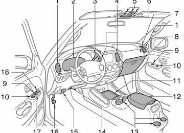
OPERATION OF INSTRUMENTS AND CONTROLS Steering wheel and Mirrors Tilt steering wheel Outside rear view mirrors Anti−glare inside rear view mirror Sun visors
. . . . . . . . . . . . . . . . . . . . . . . . . . . . . . . . . . . . . . . . . . . . . . . . . . . . . . . . . . . . . . . . . . . . . . . . . . . . . . . . . . . . . . . . . . . . . . . . . . . . . . . . . . . . . . . . . . . . . . . . . . . . . . . . . . . . . . . . . . . . . . . . . . . . . . . . . . . .
130
130
132
133129
2004 TUNDRA from Sep. ’03 Prod. (OM34426U)
’04 TUNDRA_U (L/O 0309)
Tilt steering wheel
Outside rear view mirrors—
CAUTION
D Do not adjust the steering wheel while the vehicle is moving. Doing so may cause the driver to mishan- dle the vehicle and an accident may occur resulting in death or serious injuries.
D After adjusting the steering wheel, try moving it up and down to make sure it is locked in position.
To change the steering wheel angle, hold the steering wheel, pull the lock release lever toward you, tilt the steer- ing wheel to the desired angle and re- lease the lever. When the steering wheel is in a low posi- tion, it will spring up as you release the lock release lever.
130
Adjust the mirror so that you can just see the side of your vehicle in the mir- ror. Be careful when judging the size or dis- tance of any object seen in the outside rear view mirror on the passenger’s side because it is a convex mirror. Any object seen in a convex mirror will look smaller and farther away than when seen in a flat mirror.
2004 TUNDRA from Sep. ’03 Prod. (OM34426U)
’04 TUNDRA_U (L/O 0309)
—Power rear view mirror control
CAUTION
D Do not adjust the mirror while the vehicle is moving. Doing so may cause the driver to mishandle the vehicle and an accident may occur resulting in death or serious inju- ries.
D On some models, since the mirror surfaces can get hot, do not touch them when the outside rear view mirror heater switch is on.
Standard and access cab models
To adjust a mirror, use the switches. 1. Master switch—To select the mirror to
be adjusted Push (right).
the switch to “L” (left) or “R”
2. Control switch—To move the mirror
Push the switch in the desired direc- tion.
Mirrors can be adjusted when the key is in the “ACC” or “ON” position.
NOTICE
If ice should jam the mirror, do not operate the control or scrape the mir- ror face. Use a spray de−icer to free the mirror.
Double cab models
131
2004 TUNDRA from Sep. ’03 Prod. (OM34426U)
’04 TUNDRA_U (L/O 0309)
—Folding rear view mirrors
Anti−glare inside rear view mirror
CAUTION
Do not adjust the mirror while the vehicle is moving. Doing so may cause the driver to mishandle the ve- hicle and an accident may occur re- sulting in death or serious injuries.
The rear view mirrors can be folded backward for parking in compact areas. To fold the rear view mirror, push back- ward.
CAUTION
Do not drive with the mirrors folded backward. Both the driver and pas- senger side rear view mirrors must be extended and properly adjusted before driving.
Adjust the mirror so that you can just see the rear of your vehicle in the mir- ror. To reduce glare from the headlights of the vehicle behind you during night driving, operate the lever on the lower edge of the mirror. Daylight driving—Lever at position 1
The reflection in the mirror has greater clarity at this position. Night driving—Lever at position 2
Remember that by reducing glare you also lose some rear view clarity.132
2004 TUNDRA from Sep. ’03 Prod. (OM34426U)
’04 TUNDRA_U (L/O 0309)
Sun visors—
To block out glare, move the sun visor. To block out glare from the front—Swing down the sun visor (position 1). To block out glare from the side—Swing down the sun visor, remove it from the hook and swing it to the lateral side (posi- tion 2). If glare comes from obliquely behind you, extend the plate at the end of the visor (to position 3).
Standard and access cab models
Standard and access cab models
Double cab models
Double cab models
133
2004 TUNDRA from Sep. ’03 Prod. (OM34426U)
’04 TUNDRA_U (L/O 0309)
—Vanity mirrors (with light)
To use the vanity mirrors, swing down the sun visor and open the cover. The vanity light(s) comes on when you open the cover.
Standard and access cab models
To block the glare from the front when the main sun visor is swung to the lateral side (position 2), swing down the sub vi- sor.
CAUTION
Do not extend the plate at the end of the sun visor when the visor is in the position 1. It can cover the anti−glare inside rear view mirror and obstruct the rear view.
134
Double cab models
2004 TUNDRA from Sep. ’03 Prod. (OM34426U)
’04 TUNDRA_U (L/O 0309)
SECTION 1− 5
OPERATION OF INSTRUMENTS AND CONTROLS Lights and Wipers Headlights and turn signals Emergency flashers Instrument panel light control Front fog lights Interior light Personal lights Center interior and personal lights Ignition switch and step lights Cargo lamp Windshield wipers and washer Outside rear view mirror heaters Rear window and outside rear view mirror defoggers
. . . . . . . . . . . . . . . . . . . . . . . . . . . . . . . . . . . . . . . . . . . . . . . . . . . . . . . . . . . . . . . . . . . . . . . . . . . . . . . . . . . . . . . . . . . . . . . . . . . . . . . . . . . . . . . . . . . . . . . . . . . . . . . . . . . . . . . . . . . . . . . . . . . . . . . . . . . . . . . . . . . . . . . . . . . . . . . . . . . . . . . . . . . . . . . . . . . . . . . . . . . . . . . . . . . . . . . . . . . . . . . . . . . . . . . . . . . . . . . . . . . . . . . . . . . . . . . . . . . . . . . . . . . . . . . . . . . . . . . . . . . . . . . . . . . . . . . . . . . . . . . . . . . . . . . . . . . . . . . . . . . . . . . . . . . . . . . . . . . . . . . . . . . . . . . . . . . . . . . . . . . . . . . . . . . . . . . . . . . . . . . . . . . . . . . . . . . . . . . . . . . . . . . . . . . . . . . . . . . . . . . . .
136
137
138
138
139
139
140
141
142
143
144
145135
2004 TUNDRA from Sep. ’03 Prod. (OM34426U)
’04 TUNDRA_U (L/O 0309)
NOTICE
To prevent the battery from being dis- charged, do not leave the lights on for a long period when the engine is not running.
the
Daytime running light system (on some models) The headlights turn on at reduced intensi- ty when the parking brake is released with the engine started, even with light switch in the “OFF” position. They will not go off until the ignition switch is turned off. To turn on the other exterior lights and instrument panel lights, twist the knob to the position 1. Twist the knob to the position 2 to turn the headlights to full intensity for driving at night.
Headlights and turn signals
HEADLIGHTS To turn on the following lights: Twist the headlight/turn signal lever knob. Position 1—Parking, tail, license plate and instrument panel lights Position 2—Headlights and all of above The lights automatically turn off when the driver’s door is opened with the ignition turned off. To turn them on again, turn the key to the “ON” position or actuate the headlight switch. If you are going to park for over one week, make sure the head- light switch is off.
the
136
High−Low beams—For high beams, turn the headlights on and push the lever away from you (position 1). Pull the lever to- ward you (position 2) for low beams. The headlight high beam light indicator (blue light) on the instrument panel will tell you that the high beams are on. Flashing the high beam headlights (position 3)—Pull the way back. The high beam headlights turn off when you release the lever. You can flash the high beam headlights with the knob turned to “OFF”.
the lever all
2004 TUNDRA from Sep. ’03 Prod. (OM34426U)
’04 TUNDRA_U (L/O 0309)
Emergency flashers
NOTICE
To prevent the battery from being dis- charged, do not leave the switch on longer than necessary when the en- gine is not running.
TURN SIGNALS To signal a turn, push the headlight/ turn signal lever up or down to position 1. The key must be in the “ON” position. The lever automatically returns after you make a turn, but you may have to return it by hand after you change lanes. To signal a lane change, move the lever up or down to the pressure point (position 2) and hold it. If the turn signal indicator lights (green lights) on the instrument panel flash faster than normal, a front or rear turn signal bulb is burned out.
flashers,
turn on
the emergency
To push the switch. All the turn signal lights will flash. To turn them off, push the switch once again. Turn on the emergency flashers to warn other drivers if your vehicle must be stopped where it might be a traffic hazard. Always pull as far off the road as pos- sible. The turn signal light switch will not work when the emergency flashers are operat- ing.
137
2004 TUNDRA from Sep. ’03 Prod. (OM34426U)
’04 TUNDRA_U (L/O 0309)
Instrument panel light control
Front fog lights
To adjust the brightness of the instru- ment panel lights, turn the knob.
Standard and access cab models
To turn on the front fog lights, twist the band of the headlight/turn signal lever. They will come on only when the headlights are on low beam.
Double cab models
138
2004 TUNDRA from Sep. ’03 Prod. (OM34426U)
’04 TUNDRA_U (L/O 0309)
Interior light
Personal lights
Standard and access cab models
To turn on the interior light, slide the switch. The interior light switch has the following positions: “ON”—Keeps the light on all the time. “OFF”—Turns the light off. “DOOR”—Turns light on when any door is opened. The light goes off when all the doors are closed.
the
Double cab models
Standard and access cab models— To turn on the light, push the lens on your side. To turn the light off, push the lens once again. The personal light switch has the following positions: “OFF”—Turns the lights off. “DOOR”—Turns the lights on when any of the doors are opened. Double cab models— To turn on the personal light, push the switch. To turn the light off, push the switch once again.
139
2004 TUNDRA from Sep. ’03 Prod. (OM34426U)
Center interior and personal lights
Type A
Type B
140
’04 TUNDRA_U (L/O 0309)
CENTER INTERIOR LIGHT Type A— To turn on the interior light, slide the switch. The interior light switch has the following positions: “ON”—Keeps the light on all the time. “OFF”—Turns the light off. “DOOR”—Turns the light on when any of the doors is opened. The light remains on when all the doors are closed. Type B— To turn on the interior lights, push the switch. The interior light switch has the following positions: “DOOR”—Turns the lights on when any of the doors is opened. The light remains on when all the doors are closed. “OFF”—The lights are off unless you oper- ate either outside switch.
ILLUMINATED ENTRY SYSTEM When the switch is in the “DOOR” posi- tion and any of the doors is opened, the light will come on. After all the doors are closed, the light remains on for a certain time before fading out. However, in the following cases, the light goes out immediately: D All the doors are closed when the igni- tion key is in “ACC” or “ON” position. D The ignition key is turned to “ACC”, “ON” or “START” after all the doors are closed.
D All the doors are locked when the light
is still on.
When all the doors are unlocked using either the key or the wireless remote con- trol transmitter simultaneously, the lights come on for about 15 seconds before fad- ing out. The following adjustments can be made in this system. For details, contact your Toyota dealer. D Cancelling the door key or wireless re- mote control transmitter linked opera- tion
D Changing the timing for the light turn-
ing off
2004 TUNDRA from Sep. ’03 Prod. (OM34426U)
To prevent the battery being discharged, the light will automatically turn off when the key is removed and the door is left opened with the switch at “DOOR” position for 20 minutes or more. CENTER PERSONAL LIGHTS To turn on the center personal light, push the switch. To turn the light off, push the switch once again.
’04 TUNDRA_U (L/O 0309)
Ignition switch and step lights
The lights remain on for some time after all the doors are closed. However, in the following cases, the lights go off immediately. D All the doors are closed when the igni- tion key is in the “ACC” or “ON” posi- tion.
D The ignition key is turned to the “ACC”, “ON”, or “START” position after all the doors are closed.
D All the doors are closed and locked. When all the doors are unlocked using either the key or the wireless remote con- trol transmitter simultaneously, the lights will come on and remain on for about 15
seconds before fading out. To prevent the battery being discharged, the lights will automatically turn off when the key is removed and the door is left opened for 20 minutes or more. The following adjustments can be made in this system. For details, contact your Toyota dealer. D Cancelling the door key or wireless re- mote control transmitter linked opera- tionD Changing the timing for the light turn-
ing off
141
2004 TUNDRA from Sep. ’03 Prod. (OM34426U)
Standard and access cab models— For easy access to the ignition switch, the ignition switch light comes on when the driver’s door is opened. The step light also comes on when the driver’s door is opened. The ignition switch light remains on for some is closed. Double cab models— For easy access to the ignition switch, the ignition switch light comes on when any of the doors are opened. The step light also comes on when the any of the doors are opened.
the driver’s door
time after
’04 TUNDRA_U (L/O 0309)
Cargo lamp
the
this
time,
indicator
light on the
turn on: Push
the “CARGO LAMP”
The cargo lamp is designed to light up the rear deck of your vehicle. CARGO LAMP OPERATION By pushing the “CARGO LAMP” switch To the “CARGO LAMP” switch once. At instrument panel will come on. To turn off: Push switch once again. By locking and unlocking the doors (ve- hicles with the power door lock system) You can operate the cargo lump by this method when all the doors are closed and the the “ACC” or “LOCK” position or the key is removed. To turn on: Unlock the doors with the key, the power door lock switch or the wireless remote control transmitter. The cargo lamp will automatically turn off after 20 seconds. To turn off: Lock the doors with the key, the power door lock switch or the wireless remote control transmitter.
ignition switch
in
is
Standard and access cab models
Double cab models
142
2004 TUNDRA from Sep. ’03 Prod. (OM34426U)
’04 TUNDRA_U (L/O 0309)
Windshield wipers and washer (intermittent type)
By opening and closing the doors To turn on: Open any of the doors. To turn off: Close all the doors: D When the ignition switch is in the “ON” position, the cargo lamp will go off im- mediately.
D When
the
ignition switch
the “ACC” or “LOCK” position or the key is removed, the cargo lamp will automati- cally go off after 20 seconds.
in
is
CARGO LAMP AUTOMATIC POWER−OFF FUNCTION To prevent the battery being discharged, the cargo lamp will automatically go off when the lamp remains on for 30 minutes or more.
To turn on the windshield wipers, move the lever to the desired setting. The key must be in the “ON” position.