- 2009 Toyota 4runner Owners Manuals
- Toyota 4runner Owners Manuals
- 2005 Toyota 4runner Owners Manuals
- Toyota 4runner Owners Manuals
- 2002 Toyota 4runner Owners Manuals
- Toyota 4runner Owners Manuals
- 2010 Toyota 4runner Owners Manuals
- Toyota 4runner Owners Manuals
- 2012 Toyota 4runner Owners Manuals
- Toyota 4runner Owners Manuals
- 2001 Toyota 4runner Owners Manuals
- Toyota 4runner Owners Manuals
- 2015 Toyota 4runner Owners Manuals
- Toyota 4runner Owners Manuals
- 2006 Toyota 4runner Owners Manuals
- Toyota 4runner Owners Manuals
- 2004 Toyota 4runner Owners Manuals
- Toyota 4runner Owners Manuals
- 2003 Toyota 4runner Owners Manuals
- Toyota 4runner Owners Manuals
- 2008 Toyota 4runner Owners Manuals
- Toyota 4runner Owners Manuals
- 2014 Toyota 4runner Owners Manuals
- Toyota 4runner Owners Manuals
- 2000 Toyota 4runner Owners Manuals
- Toyota 4runner Owners Manuals
- 2011 Toyota 4runner Owners Manuals
- Toyota 4runner Owners Manuals
- 2007 Toyota 4runner Owners Manuals
- Toyota 4runner Owners Manuals
- Download PDF Manual
-
tem.
To prevent fogging up of the windshield, the air intake mode may change automati- cally to FRESH depending on the condi- tion of the air conditioning system. For example, when the ambient tempera- ture intake mode may change automatically to FRESH. This is not a malfunction.
the air
low,
is
07 12.25
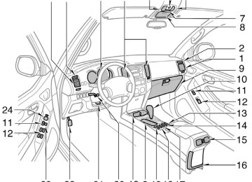
Controls (with “DUAL” button)
CY18027
1. Fan speed selector 2. Temperature selector
(at the independent mode: for driver) (at the linked mode: for driver and front passenger)
3. “AUTO” button 4. “DUAL” button 5. Temperature selector (for front passenger)
6. Air flow selector 7. Air intake selector 8. “A/C” button 9. “OFF” button
293
07 12.25
“AUTO” button For automatic operation of the air condi- tioning, push the “AUTO” button. An indi- cator light will illuminate to show that the automatic operation mode has been se- lected. In the automatic operation mode, the air conditioning selects the most suitable fan speed, air flow, air intake and on−off of the air conditioning according to the tem- perature. When you push the “AUTO” button with the air intake mode at FRESH, internal circulation may be applied for maximum cooling. You may use manual controls if you want to select your own settings. Fan speed selector Select the mode button you desire to ad- just the fan speed and push it. An indica- tor light will illuminate to show which fan speed mode is being selected. In automatic operation, you do not have to adjust the fan speed unless you desire another fan speed mode.
294
the mode
the button changes
Temperature selector To increase the temperature, push the “Ɯ” side, to decrease it, push the “Ɲ” side. “LO” appears when you adjust to maxi- mum cooling, and “HI” appears when you adjust to maximum warming. “DUAL” button This button is used to set the tempera- tures independently for the driver’s seat and front passenger seat. Pushing from independent and linked. Independent mode: Temperatures can be set independently for the driver’s seat and front passenger’s seat. An indicator light will illuminated to show that the indepen- dent mode has been selected. Linked mode: The same temperature is set for the driver’s seat and front passen- ger’s seat. When the temperature for the front pas- senger’s seat is changed in linked mode, the mode is changed automatically to in- dependent mode. “OFF” button Push the “OFF” button to turn off the air conditioning system.
CY18014
illuminate
to select
the buttons
to show which air
Air flow selector Push one of the vents used for air flow. An indicator light will flow mode is being selected. In automatic operation, you do not have to select the air flow unless you desire another air flow mode. 1. Panel—Air
the panel vents and rear vents.
instrument
flows
from
2. Bi−level—Air flows from both the floor vents, the instrument panel vents and rear vents.
3. Floor—Air flows mainly from the floor
vents.
07 12.25
4. Floor/Windshield—Air
the
flows mainly from floor vents and windshield vents and fan speed may increase in order to clean up the front view. This button allows to select FRESH automatically. This is to clean up the front view more quickly. If you want to return the setting to RECIRCULATE mode, press the air in- take selector button once again.
the air
intake
5. Windshield—Air flows mainly from the windshield vents and fan speed may increase in order to clean up the front view. Pressing this button once again returns the air flow mode to the last one used. This button allows to select FRESH automatically. This is to clean up the front view more quickly. It is not possible to return to RECIR- CULATE in this mode.
the air
intake
For details about air flow selector settings, see “Air flow selector settings” described below.
If the ambient temperature is low when the engine switch is turned to the “ON” position, the air intake mode is always set to FRESH even though the previous mode was RECIRCULATE. “A/C” button To turn on the air conditioning, push the “A/C” button. The “A/C” button indicator will come on. To turn the air conditioning off, push the button again. If the “A/C” button indicator flashes, there is a problem in the air conditioning system and the air conditioning automatically shuts off. If this happens, take your ve- hicle to your Toyota dealer for service.
CY18004
Air intake selector Push the button to select the air source. An indicator light will illuminate to show which the air source is being selected. 1. Recirculate—Recirculates the air inside
the vehicle.
2. Fresh—Draws outside air into the sys-
tem.
To prevent fogging up of the windshield, the air intake mode may change automati- cally to FRESH depending on the condi- tion of the air conditioning system. For example, when the ambient tempera- ture intake mode may change automatically to FRESH. This is not a malfunction.
the air
low,
is
295
07 12.25
Air flow selector settings
CY18015y
Operating tips D To cool off your Toyota after
it has been parked in the hot sun, drive with the windows open for a few minutes. This vents the hot air, allowing the air conditioning to cool the interior more quickly.
D Make sure the air intake grilles in front of the windshield are not blocked (by leaves or snow, for example).
D On humid days, do not blow cold air on the windshield. The windshield could fog up because of the difference in air temperature on the inside and outside of the windshield.
D Keep the area under the front seats clear to allow air to circulate through- out the vehicle.
for a minute
D On cold days, set the fan speed to high the intake ducts of snow or moisture. This can reduce the amount of fogging on the windows.
to help clear
296
D When driving on dusty roads, close all windows. If dust thrown up by the ve- hicle is still drawn into the vehicle after closing the windows, it is recommended that the air intake selector be set to FRESH and the fan speed selector to any setting except “OFF”.
07 12.25
D If following another vehicle on a dusty road, or driving in windy and dusty conditions, it is recommended that the air intake selector be temporarily set to RECIRCULATE, which will close off the outside passage and prevent outside air and dust from entering the vehicle interior.
Heating For best results, set controls as follows: For automatic operation—
Air conditioning For best results, set controls as follows: For automatic operation—
Press in the “AUTO” button. Temperature—To the desired
temperature
Air intake—FRESH (outside air) Air conditioning—OFF
Press in the “AUTO” button. Temperature—To the desired
temperature
Air intake—FRESH (outside air) Air conditioning—ON
For manual operation—
For manual operation—
Fan speed—To the desired fan speed Temperature—Towards WARM Air intake—FRESH (outside air) Air flow—FLOOR Air conditioning—OFF
Fan speed—To the desired fan speed Temperature—Towards COLD Air intake—FRESH (outside air) Air flow—PANEL Air conditioning—ON
for a
few minutes. To keep
D For quick heating, select recirculated air the windows from fogging, select fresh af- ter the vehicle interior has been war- med.
D Press the “A/C” button on for dehumidi-
fied heating.
D Choose floor/windshield air flow to heat the vehicle interior while defrosting or defogging the windshield.
D For quick cooling, select recirculated
air for a few minutes.
297
07 12.25
Ventilation For best results, set controls as follows: For automatic operation—
Press in the “AUTO” button. Temperature—Towards low temperature Air intake—FRESH (outside air) Air conditioning—OFF
For manual operation—
Fan speed—To the desired fan speed Temperature—Towards COLD Air intake—FRESH (outside air) Air flow—PANEL Air conditioning—OFF
298
the “A/C” button
Press for dehumidified heating or cooling. This setting clears the front view more quickly. D On humid days, do not blow cold air on the windshield—the difference be- tween the outside and inside tempera- tures could make the fogging worse.
—The outside of the windshield For best results, set controls as follows: —For automatic operation
Temperature—Towards high temperature Air intake—FRESH (outside air) Air flow—WINDSHIELD
—For manual operation
Fan speed—To the desired fan speed Temperature—Towards high temperature Air intake—FRESH (outside air) Air flow—WINDSHIELD
Defogging and defrosting —The inside of the windshield For best results, set controls as follows: —For automatic operation
Temperature—Towards high temperature to heat; low temperature to cool
Air intake—FRESH (outside air) Air flow—WINDSHIELD
—For manual operation
Fan speed—To the desired fan speed Temperature—Towards high temperature to heat; low temperature to cool
Air intake—FRESH (outside air) Air flow—WINDSHIELD
the windshield air
Pressing flow button turns on the defogging function with the purpose of clearing the front view. When pressing the windshield air flow but- ton, the air intake selects FRESH auto- matically. This is to clean up the front view more quickly. It is not possible to return to RECIRCU- LATE in this mode.
07 12.25
the windshield air
Pressing flow button turns on the defogging function with the purpose of clearing the front view. When pressing the windshield air flow but- ton, the air intake selects FRESH auto- matically. This is to clean up the front view more quickly. It is not possible to return to RECIRCU- LATE in this mode. Press for dehumidified heating or cooling. This setting clears the front view more quickly. D To heat the vehicle interior while de- choose
the “A/C” button
windshield,
frosting floor/windshield air flow.
the
Instrument panel and rear vents
CY18006
CY18017
Center vents
Rear vents
If air flow control is not satisfactory, check the instrument panel and rear vents. The instrument panel and rear vents may be opened or closed as shown.
CY18005
Side vents
299
07 12.25
Air conditioning filter—
CY72020
CY72003
The air conditioning filter information label is placed on the upper right side of the glove box as shown and indi- cates that a filter has been installed. The air conditioning filter prevents dust from entering the vehicle through the air conditioning vent.
The air conditioning filter is behind the glove box.
300
—Checking and replacing the air conditioning filter The air conditioning filter may clog af- ter long use. The filter may need to be replaced if the air flow of the air condi- tioning and heater experiences extreme reductions in operating efficiency, or if the windows begin to fog up easily. To maintain the air conditioning efficiency, inspect and replace the air conditioning filter the maintenance schedule. In dusty areas or areas with heavy traffic flow, such as inner city or desert areas, early replacement may be required. scheduled maintenance information, please refer to the “Scheduled Maintenance Guide” or “Owner’s Manual Supplement”.)
according
(For
to
07 12.25
CY72012
CY72004
CY72013
1. Open
the glove box. Remove
the screw with a Phillips−head screw- driver and slide the hook as shown.
2. Push in each side of the glove box
to disconnect the claws.
3. Remove the filter case by holding
both sides.
301
07 12.25
CY18022
INFORMATION
The air filter should be installed prop- erly in position. The use of air condi- tioning with filter removed may cause deteriorated dustproof per- formance and then affect air condi- tioning performance.
the air
4. Remove
case.
the
filter
from
the
filter
5. Inspect the filter on the surface. If it is the just moderately dusty, it may be cleaned by blowing compressed air from the reverse surface. Do not wash or oil the filter. If it is dirty, it should be replaced. When setting the filter to the filter case, ensure that the flat side of the filter is down and the ribbed side is up. Position the filter case so that the “↑UP” mark is pointing up and install it in the vehicle.
302
07 12.25
SECTION 1− 10
OPERATION OF INSTRUMENTS AND CONTROLS Other equipment Multi−information display Compass Rear view monitor system Power outlet Glove box Garage door opener Auxiliary boxes Rear console box Tissue box holder Coin holder Trash holder Front cup holders Rear cup holders and tray Rear cup holders Bottle holders Tie−down hooks Grocery bag hooks Cargo net hooks Luggage cover Double deck Roof luggage carrier Floor mat
. . . . . . . . . . . . . . . . . . . . . . . . . . . . . . . . . . . . . . . . . . . . . . . . . . . . . . . . . . . . . . . . . . . . . . . . . . . . . . . . . . . . . . . . . . . . . . . . . . . . . . . . . . . . . . . . . . . . . . . . . . . . . . . . . . . . . . . . . . . . . . . . . . . . . . . . . . . . . . . . . . . . . . . . . . . . . . . . . . . . . . . . . . . . . . . . . . . . . . . . . . . . . . . . . . . . . . . . . . . . . . . . . . . . . . . . . . . . . . . . . . . . . . . . . . . . . . . . . . . . . . . . . . . . . . . . . . . . . . . . . . . . . . . . . . . . . . . . . . . . . . . . . . . . . . . . . . . . . . . . . . . . . . . . . . . . . . . . . . . . . . . . . . . . . . . . . . . . . . . . . . . . . . . . . . . . . . . . . . . . . . . . . . . . . . . . . . . . . . . . . . . . . . . . . . . . . . . . . . . . . . . . . . . . . . . . . . . . . . . . . . . . . . . . . . . . . . . . . . . . . . . . . . . . . . . . . . . . . . . . . . . . . . . . . . . . . . . . . . . . . . . . . . . . . . . . . . . . . . . . . . . . . . . . . . . . . . . . . . . . . . . . . . . . . . . . . . . . . . . . . . . . . . . . . . . . . . . . . . . . . . . . . . . . . . . . . . . . . . . . . . . . . . . . . . . . . . . . . . . . . . . . . . . . . . . . . . . . . . . . . . . . . . . . . . . . . . . . . . . . . . . . . . . . . . . . . . . . . . . . . . . . . . . . . . . . . . . . . . . . . . . . . . . . . . . . . . . . . . . . . . . . . . . . . . . . . . . . . . . . . . . . . . . . . . . . . . . . . . . . . . . . . . . . . . . . . . . . . . . . . . . . . . . . . . . . . . . . . . . . . . . . . . . . . . . . . . . . . . . . . . . . . . . . . . . . . . . . . . . . . . . . . . . . . . . . . . . . . . . . . . . . . . . . . . . . . . . . . . . . . . . . . . . . . . . . . . . . . . . . . . . . . . . . . . . . . . . . . . . . . . . . . . . . . . . . . . . . . . . . . . . . . . . . . . . . . . . . . . . . . .
304
307
312
315
317
318
322
324
325
326
326
327
328
330
330
331
331
332
332
333
334
336303
07 12.25
Multi−information display—
CY19142
304
1. “RESET” button 2. “MODE” button 3. Air conditioning system without “DUAL”
button—Cruise information display Air conditioning system with “DUAL” button—Outside temperature and cruise information display
4. Clock 5. Air conditioning system without “DUAL”
button only—Outside temperature display
6. “:00” button 7. “M” button 8. “H” button
07 12.25
the multi−information display
—Before using the multi−information display Operate with the engine switch on. When the engine switch is turned to “ON”, the last previously used mode displayed just before the engine switch is turned off will appear. If the electrical power source has been disconnected the multi−information display, the display will automatically be set to the initial mode.
from
CAUTION
Do not adjust the display while the vehicle is moving. Be sure to adjust the display only when the vehicle is stopped.
—Clock
—Outside temperature display (air conditioning system without “DUAL” button)
CY19001
CY19082
the
time
To reset the hour: Push the “H” button. To reset the minutes: Push the “M” button. If quick adjustment to a full hour is de- sired, push the “:00” button. if the “:00” button is de- For example, pressed when is between 1:01—1:29, the time will change to 1:00. If the time will change to 2:00. The engine switch must be in the “ACC” or “ON” position. If the electrical power source has been disconnected from the clock, the time dis- play will automatically be set to 1:00 (one o’clock).
is between 1:30—1:59,
time
the
from
temperature
the outside air
The displayed ranges −30_C (−22_F) up to 50_C (122_F). The engine switch must be in the “ON” position. If an abnormality exists in the connection of temperature sensor, “−−_C” (“−−_F”) will appear on the display. If “−−_C” (“−−_F”) appears on the display, contact your Toyota dealer. There may be a case that “−−_C” (“−−_F”) the engine appears momentarily when switch is normal if it goes out soon.
is quickly
to “ON”.
turned
It
305
07 12.25
—Cruise information display
Air conditioning system with “DUAL” button only—
CY19121
306
temperature display
The outside (air conditioning system with “DUAL” but- ton) and cruise information display indi- cates the following information. Every time you push the “MODE” but- ton, the display toggles through this information. 1. Outside temperature 2. Driving range 3. Average fuel consumption 4. Average vehicle speed 5. Display off The displayed values in the cruise infor- mation display indicate general driving conditions. Accuracy varies with driving habits and road conditions.
1. Outside temperature (“OUTSIDE _F”
or “OUTSIDE _C”)
from
temperature
the outside air
The displayed value is updated every 1
second. The displayed ranges −30_C (−22_F) up to 50_C (122_F). If an abnormality exists in the connection of temperature sensor, “−−_C” (“−−_F”) will appear on the display. If “−−_C” (“−−_F”) appears on the display, contact your Toyota dealer. There may be a case that “−−_C” (“−−_F”) the engine appears momentarily when switch is normal if it goes out soon.is quickly
to “ON”.
turned
It
07 12.25
2. Driving range
(“RANGE MI” or “RANGE km”)
3. Average fuel consumption
(“AVG. MPG” or “AVG. L/100 km”)
Compass
It
the
fuel
indicates
fuel gauge reaches “E”.
The distance the vehicle can travel with the remaining is calculated and displayed based on the quantity of re- maining fuel and past fuel consumption. The driving range display the approximate distance that you can drive until is different from the actual distance traveled. The displayed value is updated about ev- ery 10 seconds. Every time you refuel the vehicle, the cal- culation is reset. However, when only a small amount of fuel is added to the tank, the display may not be reset. The actual driving range varies with driv- ing habits and road conditions. If fuel con- sumption is good, the driving range will be longer than indicated. If fuel consumption is poor, the driving range will be shorter than indicated. If the low fuel level warning light comes on, refuel the vehicle even if the display indicates that the vehicle can be driven further.
total
Average fuel consumption is calculated and displayed based on total driving distance and fuel consumption with the engine running. The displayed value is updated about ev- ery 10 seconds. To the “RESET” button about 1 second. 4. Average vehicle speed
calculation,
reset
push
the
(“AVG. MPH” or “AVG. km/h”)
Average vehicle speed is calculated and displayed based on total driving dis- tance and total driving time with the engine running. The displayed value is updated about ev- ery 10 seconds. To the “RESET” button about 1 second.
calculation,
reset
push
the
CY19138
The direction is indicated on the inside rear view mirror. If the engine switch was turned off with the system on, the system will automati- cally turn back on when the engine switch is turned on.
Push the “ system on and off.
” switch to turn the compass
307
07 12.25
indicates
the vehicle
the direction The compass that the above case, it shows that the vehicle is heading north.
is heading.
In
Displays
NE SE SW NW
Directions
North
Northeast
East
Southeast
South
Southwest
West
Northwest
The compass may not show the correct direction in the following conditions: D The vehicle is stopped immediately af-
ter turning.
D The compass does not adjust while the
vehicle is stopped.
D The engine switch is turned off immedi-
ately after turning.
D The vehicle is on an inclined surface.
308
D The vehicle is in a place where the earth’s magnetic field is subject to in- terference by artificial magnetic fields (underground parking, under a steel tower, between buildings, roof parking, near a crossing, near a large vehicle, etc.).
D The vehicle is magnetized. (There is a magnet or a metal object on or near the inside rear view mirror.)
the deviation
D The battery has been disconnected. If your vehicle is out of the set zone, refer to “CALIBRATING THE COMPASS” below to set the zone number. If the compass works to calibrate the direction automati- cally while the vehicle is in motion. For additional precision or calibrating, see COMPASS” below.
for complete THE
“CALIBRATING
is small,
CY19139
Compass sensor
The compass sensor is in the inside rear view mirror.
NOTICE
Do not put magnets or a metal object on or near the inside rear view mirror of the vehicle. Doing this may cause malfunction of the compass sensor.
07 12.25
CY19140
the
from
CALIBRATING THE COMPASS (deviation calibration) the compass The direction display on true direction deter- deviates mined by the earth’s magnetic field. The angle of deviation varies according to the geographic position of the vehicle. To adjust this deviation, stop the vehicle, ” switch until then push and hold the “ the zone number appears on the display. Then push the “ ” switch, referring to the following map to select the number of the zone where the vehicle is.
309
Samoa: 5
Guam:
Saipan: 8
After calibration, leaving the system for several seconds returns it to the compass mode.
CAUTION
Do not adjust the display while the vehicle is moving. Be sure to adjust the display only when the vehicle is stopped.
Z19004y
07 12.25
Zone numbers
310
07 12.25
CY19141
CY19033
the direction display on
CALIBRATING THE COMPASS (circling calibration) Sometimes the compass may not change after a turn. To rectify this, stop the vehicle and push and hold the “ ” switch until “C” appears on the display. If “C” appears on the display because of a drastic change in the magnetic field, perform circling calibration.
in a circle, drive around
Drive the vehicle in a circle at 8 km/h (5
mph) or less. If there is not enough space to drive the block. After driving 1 to 3 circles in the above method, calibration is completed when the direction is shown on the display. If calibration cannot be performed because of the magnetized vehicle etc., take your vehicle to Toyota dealer.Perform circling calibration just after you have purchased your Toyota. And then always perform circling calibration after the battery has been removed, re- placed or disconnected. D Do not perform circling calibration of the compass the earth’s magnetic field is subject to in- terference by artificial magnetic fields (underground parking, under a steel tower, between buildings, roof parking, near a crossing, near a large vehicle, etc.).
in a place where
D During calibration, do not operate elec- tric systems (moon roof, power win- dows, etc.) as they may interfere with the calibration.
311
07 12.25
CAUTION
D When doing the circling calibration, be sure to secure a wide space, and watch out for people and ve- hicles in the neighborhood. Do not violate any local traffic rules while performing circling calibration.
D Do not adjust the display while the vehicle is moving. Be sure to adjust the display only when the vehicle is stopped.
312
Rear view monitor system The rear view monitor system assists the driver by displaying an image of the view behind the vehicle while back- ing up. The image is displayed in re- verse on the screen. This allows the image to appear in the same manner as that of the rear view mirror. To display the rear view image on the screen, place the selector lever in the “R” position when the engine switch is in the “ON” position. If you move the selector lever out of the “R” position, the previous screen. Operating another func- tion of the navigation system will display another screen. The rear view monitor system is a supple- ment device intended to assist back up. When backing up, be sure to check be- hind and all around the vehicle visually.
the screen returns
to
CAUTION
the
D Never depend on
rear view monitor system entirely when back- ing up. Always make sure your in- tended path is clear. Use caution, when backing up any vehicle.
just as you would
image on
D Never back up while looking only at the screen. The the screen is different from actual con- ditions. Depicted distances between objects and flat surfaces will differ from actual distance. If you back up while looking only at the screen, you may hit a vehicle, a person or an object. When backing up, be sure to check behind and all around the vehicle visually and with mir- rors before proceeding.
07 12.25
D Do not use the system when the back door is not completely closed. D If the back of the vehicle is hit, the position and mounting angle of the camera may change. Be sure to have the camera’s position and mounting angle checked at your Toyota dealer.
D If the temperature changes rapidly, such as when hot water is poured on the vehicle in cold weather, the system may not operate normally.
D If the camera lens becomes dirty, it cannot transmit a clear If water droplets, snow, or mud ad- here to the lens, rinse with water and wipe with a soft cloth. If the lens is extremely dirty, wash it with a mild cleanser and rinse.
image.
When replacing the tires, please consult your Toyota dealer. If you replace the tires, the area displayed on the screen may change.
D Use your own eyes to confirm the vehicle’s surroundings, as the dis- played image may become faint or dark, and moving images will be distorted, or not entirely visible when is low. When backing up, be sure to check behind and all around the ve- hicle visually and with mirror before proceeding.
the outside
temperature
NCY002
On screen
Corners of bumper
313
07 12.25
AREA DISPLAYED ON SCREEN Image is displayed approximately level on screen. D The area detected by the camera is limited. The camera does not detect objects which are close to either corner of the bumper or under the bumper.
D The area displayed on the screen may vary according to vehicle orien- tation or road conditions.
CY19136
THE REAR VIEW MONITOR SYSTEM CAMERA The rear view monitor system camera is located on the back door as shown in the illustration. The camera uses a special lens. The distance of the image that ap- pears on the screen differs from the actu- al distance. In it may become difficult to see the images on the screen, even when the system is functioning. D In the dark (for example, at night) D When the temperature near the lens is
following cases,
the
314
high or low
D When water droplets are adhering to the camera, or when humidity is high (for example, when it rains)
D When
foreign matter
(for example, snow or mud) is adhering to the cam- era
D When the sun or the beam of head- lights is shining directly into the cam- era lens
07 12.25
Power outlet (12 VDC)
CY19118
CY19002
If a bright light (for example, sunlight re- flected off the vehicle body) is picked up by the camera, the smear effect∗ peculiar to the camera may occur. ∗: Smear effect—A phenomenon that oc- curs when a bright light (for example, sun- light reflected off is picked up by trans- mitted by light source appears to have a vertical streak above and below it.
the camera; when
the vehicle body)
the camera,
the
CY19035
Luggage compartment
for
The power outlets are designed power supply for car accessories. In the rear console box—To use the power outlet, push the lid of the auxil- iary box to open. The engine switch must be in the “ACC” or “ON” position for the power outlet to be used.
Rear console box
315
07 12.25
Power outlet (115 VAC)
NOTICE
the
fuse
z To prevent
from being blown, do not use the electricity over the total vehicle capacity of 12
VDC/120W.z To prevent the battery from being discharged, do not use the power outlets longer than necessary when the engine is not running.
z Close the power outlet
lids when the power outlets are not in use. Inserting anything other than an ap- propriate plug that fits the outlet, or allowing any liquid to get into the outlet may cause electrical fail- ure or short circuits.
316
CY19137
CY19135
This power outlet is designed for use as a power supply for electric ap- pliances in the vehicle. The engine switch must be in the “ON” position for the power outlet to be used. The maximum capacity for this power out- let is 115 VAC/100W. If you attempt to use an appliance that requires more than 115 VAC or 100W, the protection circuit will activate and cut the power supply. The power supply will restart automatically when you use an appliance that operates within the 115 VAC/100W limits.
To use the power outlet, push the main switch on the instrument panel. An indicator light will illuminate to indicate that the power outlet is ready for use. Push the main switch once again to turn the power outlet off. When the power out- let is not in use, make sure that the main switch is turned off.
07 12.25
NOTICE
z To prevent the battery from being discharged, do not use the power outlet longer than necessary when the engine is not running.
z Close the power outlet lid when the power outlet is not in use. Inserting anything other than an appropriate plug that fits the outlet may cause electrical failure or short circuits.
The power outlet is not designed for the following electric appliances even though their power consumption is un- der 115 VAC/100W. These appliances may not operate properly.
D Appliances with high initial peak watt- age: cathode−ray tube type televisions, compressor−driven refrigerators, electric pumps, electric tools, etc.
D Measuring devices which process pre- cise data: medical equipment, measur- ing instruments, etc.
D Other appliances requiring an extremely stable power supply: microcomputer− controlled electric blankets, touch sen- sor lamps, etc.
Certain electrical appliances may cause radio noise.
Glove box
CY19127
To use the glove box: Open by pulling the lever. Lock by inserting the master key and turn- ing it clockwise. Unlock by inserting the master key and turning it counterclockwise. With the instrument panel lights on, the glove box light will come on.
CAUTION
To reduce the chance of in case of an accident or a sudden stop, always keep the glove box door closed while driving.
injury
317
07 12.25
CY19070
318
On some models, an auxiliary box is located inside the glove box. To increase the capacity of the glove box, raise the lower panel of the auxiliary box.
Garage door opener
Indicator light
CY19130
Buttons
The garage door opener ( Universal Transceiver) is manufactured under license from HomeLinkR and can be programmed to operate garage doors, gates, entry doors, door locks, home lighting systems, and security systems, etc.
07 12.25
transmitter prior
(a) Programming the HomeLinkR The HomeLinkR in your vehicle has 3
buttons and you can store one program for each button. To ensure correct programming into the HomeLinkR, install a new battery in the hand−held to program- ming. The battery side of the hand−held trans- mitter must be pointed away the HomeLinkR during the programming pro- cess. For Canadian users, follow the procedure “Programming an entrance gate/pro- in gramming all devices the Canadian market”. 1. Decide which of 3 HomeLinkR buttonsfrom
in
you want to program.
HomeLinkr
CY19131
25 to 75 mm (1 to 3 in.)
CY19132
Hand−held garage transmitter
2. Place your hand−held garage transmit- ter 25 to 75 mm (1 to 3 in.) away from the surface of the HomeLinkR.
Keep the indicator light on the HomeLinkR in view while programming.
3. Simultaneously press and hold
the hand−held garage transmitter button along with the selected HomeLinkR but- ton.
Do not release the buttons until step 4
has been completed. 4. Whenthe HomeLinkR changes from a slow to a rapid flash after 20 seconds, you can release both buttons.
light on
indicator
the
319
07 12.25
CY19034
5. Test the operation of the HomeLinkR by pressing the newly programmed button. If programming a garage door opener, check to see if the garage door opens and closes. If the garage door does not operate, identify if your garage transmitter is of the “Rolling Code” type. Press and hold the programmed HomeLinkR The garage door has the rolling code feature if the HomeLinkR) the flashes rapidly and then remains lit after 2
seconds. If your garage transmitter is the “Rolling Code” the heading rolling code system”.“Programming a
type, proceed
indicator
button.
light
(on
to
320
6. Repeat steps 2 through 5 for each re- maining HomeLinkR button to program another device.
it
is
to
is necessary
Programming a rolling code system “Rolling Code” If your device equipped, follow steps 1 through 4 under the heading “Programming the HomeLinkR” before proceeding with the steps listed below. 1. Locate the “training” button on the ceil- ing mounted garage door opener motor. The exact the button may vary by brand of garage door opener. Refer the owner’s guide supplied by the garage door opener manufacturer for the location of this “training” button.
location and color of
to
2. Press the “training” button on the ceil- ing mounted garage door opener motor. Following this step, you have 30 seconds in which to initiate step 3 below. 3. Press and release the vehicle’s pro- grammed HomeLinkR button twice. The garage door may open. the door does open, the programming process is complete. If the door does not open, press and release the button a third time. This third press and release will complete the programming process by opening the garage door.
If
now
should
recognize
The ceiling mounted garage door opener motor the HomeLinkR unit and be able activate the garage door up/down. 4. Repeat steps 1 through 3 for each re- maining HomeLinkR button to program another rolling code system.
Programming an entrance gate/program- ming all devices in the Canadian market 1. Decide which of the 3 HomeLinkR but-
2. Place
your
tons you want to program. hand−held
gate/device transmitter 25 to 75 mm (1 to 3 in.) away the HomeLinkR.
surface
from
the
of
Keep the indicator light on the HomeLinkR in view while programming. 3. Press
selected
hold
and
the
HomeLinkR button.
4. Continuously press and release (cycle) transmitter the hand−held gate/device button every two seconds until step 5
is complete. thethe HomeLinkR changes from a slow to a rapid flash after 20 seconds, you can release both buttons.
light on
5. When
indicator
07 12.25
6. Test the operation of the HomeLinkR by pressing the newly programmed button. Check to see if the gate/device oper- ates correctly.
7. Repeat steps 1 through 6 for each re- maining HomeLinkR button to program another device.
Programming other devices To program other devices such as home security systems, home door locks or lighting, contact your authorized Toyota dealer for assistance. Reprogramming a button buttons cannot be Individual HomeLinkR erased, however, to reprogram a single button, follow the procedure “Programming the HomeLinkR”. (b) Operating the HomeLinkR To operate the appropriate HomeLinkR button to activate the programmed device. The HomeLinkR indicator light should come on. The HomeLinkR continues to send the signal for up the button is pressed.
the HomeLinkR, press
to 20 seconds as
long as
your
For additional programming assistance with Universal Transceiver call the: D The
Toyota Customer Experience
HomeLinkR
CY19133
Center at 1−800−331−4331 (U.S.A.)
D Toyota Canada Customer
Interaction
Centre at 1−888−869−6828 (Canada) Refer to HomeLinkR on the internet at: WWW.HOMELINK.COM
(c) Erasing
the
entire HomeLinkR
memory (all three programs)
To erase all previously programmed codes at one time, press and hold down the 2
outside buttons for 20 seconds until the indicator light flashes. If you sell your vehicle, be sure to erase the programs stored the HomeLinkR memory.in
321
07 12.25
CAUTION
D When programming the HomeLinkR Universal Transceiver, you may be operating a garage door or other device. Make sure people and ob- jects are out of the way of the ga- rage door or other device to pre- vent potential harm or damage.
D Do not use this HomeLinkR Univer- sal Transceiver with any garage door opener that lacks the safety stop and reverse feature as re- quired by federal safety standards. (This includes any garage door opener model manufactured before April 1, 1982.) A garage door open- er which cannot detect an object (signaling the door to stop and re- verse), does not meet current feder- al safety standards. Using a garage door opener without these features increases risk of serious injury or death.
322
received,
This device complies with Part 15 of the FCC Rules and with RSS−210 of the IC Rules. Operation is subject to the fol- lowing two conditions: (1) This device may not cause harmful interference, and (2) this device must accept any interfer- ence interference that may cause undesired operation. WARNING: This transmitter has been tested and complies with FCC and IC rules. Changes or modifications not expressly approved by the party re- sponsible for compliance could void the user’s authority to operate the device.
including
Auxiliary boxes— To use the auxiliary boxes, open the lids as shown in the following illustra- tions.
CAUTION
D To reduce the chance of injury in case of an accident or a sudden stop, always keep the auxiliary box closed while driving.
D Type A—As this holder is designed for holding a light object such as eyeglasses, do not place any heavy objects in them. Heavy objects may cause the holder to open and the contents to fly out resulting in inju- ries.
NOTICE
Type A—During hot weather, the inte- rior of the vehicle becomes very hot. Do not leave anything flammable or deformable such as a lighter, glasses, etc. inside.
07 12.25
CY19005
CY19036
CY19069
Type A (overhead console)
Type C (rear console box)
Type E (right side of luggage compart- ment)
CY19007
CY19112
Type B (instrument panel)
Type D (rear tire house)
323
07 12.25
—Using the holding belts
Rear console box
CY19074
The right side of luggage compartment auxiliary box is equipped with a belt to hold the objects. To use the belt, do the following. 1. To loosen: Pull the buckle forward. 2. To tighten: Pull on the belt. Make sure the objects are securely held.
CY19071
CONSOLE BOX TABLE To use the console box table, open it.
CAUTION
To reduce the chance of in case of an accident or a sudden stop, always keep the table closed while driving.
injury
NOTICE
To prevent damage to the table, do not place any object heavier than 1
kg (2.20 lb.) on it, and do not leave any object on the table for a long time.324
07 12.25
CY19104
CONSOLE BOX To access the rear console box, pull up the console box lid while pushing the lock release button.
CAUTION
To reduce the chance of in case of an accident or a sudden stop, always keep the console box closed while driving.
injury
Tissue box holder
CY19105
The rear console box is equipped with a tissue box holder on the inside of the rear console box lid. To use the tissue box holder: 1. Pull up the console box lid while push-
ing the lock release button.
2. Place a tissue box in the lid.
CAUTION
To reduce the chance of in case of an accident or a sudden stop while driving, keep the console box lid closed when it is not in use.
injury
325
07 12.25
Coin holder
Trash holder
The rear console box is equipped with a coin holder. To use the coin holder: 1. Pull up the console box lid while push-
ing the lock release button.
2. Push coins down into the holder. The coin holder is detachable.
CY19106
CY19038
326
07 12.25
The trash holder is designed to use the grocery bag as a trash bag. To use the trash holder: 1. Raise the trash holder. 2. Fit the grocery bag onto the holder by hanging its handles on the two hooks indicated at the left and right. trash holder can support
to 1 kg
The (2.20 lb.).
CAUTION
To reduce the chance of in case of an accident or a sudden stop while driving, keep the trash holder closed when it is not in use.
injury
Front cup holders
CY19111
CY19064
If the trash holder is pulled strongly or stepped on, it will detach from the rear console box to protect it from damag- ing. If the trash holder becomes detached, re- install it in a horizontal direction as indi- cated It cannot be installed in any other direction.
illustration.
the
in
NOTICE
Do not deliberately pull or step on the trash holder, as it may be dam- aged or broken.
327
07 12.25
The cup holders are designed for hold- ing cups or drink−cans securely. The cup holder can be adjustable to the size of the cups or drink−cans by changing the holder position and the arm position, as shown. With the instrument panel lights on, the front cup holder position indicator lights will come on.
CAUTION
Do not place anything else other than cups or drink−cans in the cup holder, as such items may be thrown about in the compartment and possibly in- jured people the vehicle during sudden braking or in an accident.
in
328
Rear cup holders and tray (vehicles without third seats)
CY19075
tray are
The rear cup holders and housed in the armrest. The cup holders are designed to hold cups or beverage cans securely. 1. To use the rear cup holders and tray,
pull the armrest out.
CY19100
07 12.25
2. To use the rear cup holder, push and
pull it out.
CY19101
3. To use the tray, pull it out.
CAUTION
D Do not place anything else other than cups or drink−cans in the cup items may be holder, as such thrown about in the compartment and possibly injure people in the vehicle during sudden braking or in an accident.
D To reduce the chance of injury in case of an accident or sudden stop while driving, keep the cup holder closed when it is not in use.
D To reduce the chance of injury in case of an accident or a sudden stop, always keep the tray closed while driving.
NOTICE
To prevent damage to the tray, do not place any object heavier than 2 kg (4.40 lb.) on it, and do not leave any object on the tray for a long time.
329
07 12.25
Rear cup holders (vehicles with third seats)
Bottle holders
The cup holders are designed for hold- ing cups or drink−cans securely. Type A—To use the holder, pull the arm- rest out and push the lid.
CAUTION
D Do not place anything else other than cups or drink−cans in the cup items may be holder, as such thrown about in the compartment and possibly injure people in the vehicle during sudden braking or in an accident.
D Type A—To reduce the chance of injury in case of an accident or sudden stop while driving, keep the cup holder closed when it is not in use.
CY19015
Front doors
CY19016
Rear doors
CY19114
Type A (armrest)
CY19113
Type B (rear tire house)
330
07 12.25
The bottle holders are designed to hold bottles securely.
CAUTION
Do not attempt to use the holder for any other purpose for which it was intended. Inappropriately sized or shaped objects may be thrown about in the compartment and possibly in- jure people in the vehicle during a sudden braking or an accident.
Tie−down hooks
Grocery bag hooks
CY19044
CY19076
NOTICE
Do not put a cup or open bottle in the bottle holder because the con- tents may spill when the door opens or closes.
To secure your luggage, use the tie− down hooks as shown above. See “—Stowage precautions” on page 365
in Section 2 for precautions when loading luggage.CAUTION
To avoid personal injury, keep the tie− down hooks folded in place on the floor when not in use.
NOTICE
Do not use the seat anchors instead of the tie−down hooks.
These hooks are designed things like grocery bags.
to hang
NOTICE
To prevent damage to the hook, do not hang any object heavier than 1 kg (2.20 lb.) in it.
331
07 12.25
Cargo net hooks
Luggage cover
USING LUGGAGE COVER To use the luggage cover: 1. Attach the front hooks of the lug-
gage cover to the head restraint.
2. Pull out the rear luggage cover and
hook it on the anchors.
CAUTION
Do not place anything on the luggage cover. Such thrown about and possibly injure people in the vehicle during sudden braking or a collision.
items may be
CY19103
CY19045
These hooks are designed to hang the cargo net. To hang the cargo net, use the cargo net hooks and rear tie−down hooks. Although the cargo net itself is not in- cluded as an original equipment, these hooks can be used to hang the cargo net.
NOTICE
To prevent damage to the hook, avoid hanging things other than a cargo net on it.
332
07 12.25
Double deck
CY19067
CY19058
CY19068
To use the double deck: 1. Turn the left and right knobs from the
position
to
“LOCK”
the