- 2009 Toyota Prius Owners Manuals
- Toyota Prius Owners Manuals
- 2008 Toyota Prius Owners Manuals
- Toyota Prius Owners Manuals
- 2013 Toyota Prius Owners Manuals
- Toyota Prius Owners Manuals
- 2004 Toyota Prius Owners Manuals
- Toyota Prius Owners Manuals
- 2001 Toyota Prius Owners Manuals
- Toyota Prius Owners Manuals
- 2005 Toyota Prius Owners Manuals
- Toyota Prius Owners Manuals
- 2015 Toyota Prius Owners Manuals
- Toyota Prius Owners Manuals
- 2012 Toyota Prius Owners Manuals
- Toyota Prius Owners Manuals
- 2002 Toyota Prius Owners Manuals
- Toyota Prius Owners Manuals
- 2010 Toyota Prius Owners Manuals
- Toyota Prius Owners Manuals
- 2014 Toyota Prius Owners Manuals
- Toyota Prius Owners Manuals
- 2006 Toyota Prius Owners Manuals
- Toyota Prius Owners Manuals
- 2003 Toyota Prius Owners Manuals
- Toyota Prius Owners Manuals
- 2007 Toyota Prius Owners Manuals
- Toyota Prius Owners Manuals
- 2011 Toyota Prius Owners Manuals
- Toyota Prius Owners Manuals
- Download PDF Manual
-
†switch: Use this switch to
sired track.
D To select a desired disc, push and hold this switch until the desired number of the disc appears and you hear a beep.
CAUTION
Operate the switches with due care while you are driving to avoid acci- dents.
Car audio system operating hints
NOTICE
To ensure correct audio system op- erations: z Be careful not to spill beverages
over the audio system.
z Do not put anything other than a cassette tape into the cassette tape slot.
z The use of a cellular phone inside or near the vehicle may cause a noise from the speakers of the au- dio system which you are listening to. However, this does not indicate a malfunction.
RADIO RECEPTION Usually, a problem with radio reception does not mean there is a problem with your radio—it is just the normal result of conditions outside the vehicle. For example, nearby buildings and terrain can interfere with FM reception. Power lines or telephone wires can interfere with AM signals. And of course, radio signals have a limited range. The farther you are from a station, the weaker its signal will be. conditions change constantly as your vehicle moves.
In addition,
reception
signals are
Here are some common reception prob- lems that probably do not indicate a prob- lem with your radio: FM Fading and drifting stations—Generally, the effective range of FM is about 40 km (25
miles). Once outside this range, you may notice fading and drifting, which increase with the distance from the radio transmit- ter. They are often accompanied by distor- tion. Multi−path—FM reflective, making it possible for two signals to reach your antenna at the same time. If this happens, the signals will cancel each oth- er out, causing a momentary flutter or loss of reception. Static and fluttering—These occur when signals are blocked by buildings, trees, or other large objects. Increasing the bass level may reduce static and fluttering. the FM signal you Station swapping—If are interrupted or weak- is ened, and there is another strong station nearby on the FM band, your radio may tune in the second station until the origi- nal signal can be picked up again.listening to
they can
AM Fading—AM broadcasts are reflected by the upper atmosphere—especially at night. These reflected signals can interfere with those received directly from the radio sta- tion, causing the radio station to sound alternately strong and weak. Station interference—When a reflected sig- nal and a signal received directly from a radio station are very nearly the same frequency, interfere with each other, making it difficult to hear the broad- cast. Static—AM is easily affected by external sources of electrical noise, such as high tension power lines, lightening, or electri- cal motors. This results in static. CARING FOR YOUR CASSETTE PLAYER AND TAPES For the best performance for your cas- sette player and tapes: Clean the tape head and other parts regu- larly. D A dirty
tape head or tape path can decrease sound quality and tangle your cassette to clean them is by using a cleaning tape. (A wet type is recommended.)
tapes. The easiest way
175
D Bumpy roads or other vibrations may
make your compact disc player skip.
D If moisture gets into your compact disc player, you may not hear any sound even though your compact disc player appears the disc from the player and wait until it dries.
to be working. Remove
CAUTION
Compact disc players use an invisible laser beam which could cause hazard- ous if directed outside the unit. Be sure to operate the player correctly.
radiation exposure
D Use only compact discs marked as shown above. The following products may not be playable on your compact disc player. Copy−protected CD CD−R (CD−Recordable) CD−RW (CD−Re−writable) CD−ROM
Use high−quality cassettes: D Low−quality cassette tapes can cause many problems, including poor sound, inconsistent and constant auto−reversing. They can also get stuck or tangled in the cassette player.
playing
speed,
D Do not use a cassette if it has been damaged or tangled or if its label is peeling off.
D Do not leave a cassette in the player if you are not listening to it, especially if it is hot outside.
D Store cassettes in their cases and out
of direct sunlight.
D Avoid using cassettes with a total play- ing time longer than 100 minutes (50
minutes per side). The tape used in these cassettes is thin and could get stuck or tangled in the cassette player. CARING FOR YOUR COMPACT DISC PLAYER AND DISCS D The playerfor use with
intended 12cm (4.7 in.) discs only.
is
D Extremely high temperatures can keep your compact disc player from working. On hot days, use the air conditioning to cool the vehicle interior before you listen to a disc.
176
NOTICE
To prevent damage to the player or changer, do not use special shaped, transparent/translucent, low quality or labeled discs such as those shown in the illustrations.
Special shaped discs
Low quality discs
Z17058
Transparent/translucent discs
Labeled discs
177
To clean a compact disc: Wipe it with a soft, lint−free cloth that has been damp- ened with water. Wipe in a straight line from the center to the edge of the disc (not in circles). Dry it with another soft, lint−free cloth. Do not use a conventional record cleaner or anti−static device.
Correct
Wrong
inserting
D Handle compact discs carefully, espe- them. cially when you are them on the edge and do not Hold them. Avoid getting fingerprints bend on them, particularly on the shiny side. D Dirt, scratches, warping, pin holes, or other disc damage could cause the player to skip or to repeat a section of a track. (To see a pin hole, hold the disc up to the light.)
D Remove discs from the compact disc player when you are not listening to them. Store them in their plastic cases away from moisture, heat, and direct sunlight.
178
SECTION 2– 9
OPERATION OF INSTRUMENTS AND CONTROLS Air conditioning system Controls Climate remote control Instrument panel ventss
. . . . . . . . . . . . . . . . . . . . . . . . . . . . . . . . . . . . . . . . . . . . . . . . . . . . . . . . . . . . . . . . . . . . . . . . . . . . . . . . . . . . . . . . . . . . . . . . . . . . . . . . . . . . . . . . . . . . . . . . . . . . .
180
186
187179
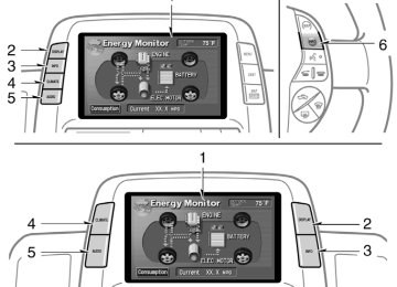
Controls
Type A (with Navigation system)
Type B (without Navigation system)
27P010g
180
1. Outside temperature display
2. Passenger
display
compartment
temperature
3. Air flow control switch
4. Fan speed control switch
5. Temperature control switch
6. OFF switch
7. Automatic control switch
8. Rear window and outside
rear view mirror defogger switch (See page 110
for details.)9. Front windshield switch
10. Air intake control switch
11. Air conditioning operation screen dis-
play button
12. Air conditioning on−off switch
this manual, English version screens
In are shown as an example.
The automatic air conditioning automat- ically maintains the set temperature. features automatic This air conditioning fan speed and air flow control which auto- matically selects fan speed and air flow to control the tempera- ture. The hybrid system must be in the “IG−ON†mode. CLIMATE: Push switches controls.
to display for automatic air conditioning
the most suitable
this button
27p005a
NOTICE
To prevent the battery from being dis- charged, do not leave the air condi- tioning on than necessary when the hybrid system is not operat- ing.
longer
Air flow selection : In the beginning of the automatic air flow mode, air might be delivered.
181
(a) Climate control SETTING OPERATION—automatic con- trol
27p111a
When one of the manual control buttons is depressed while operating in automatic mode, the mode relevant to the depressed button is set. Other conditions continue to be adjusted automatically. However, oper- ating the air flow outlets or fan speed will turn off the automatic control. Touch the “OFF†switch to turn the air conditioning off.
27p112a
2. Use the “TEMP†switch to set the
desired temperature.
The temperature of air delivered to the passenger compartment will be controlled automatically according to the setting.
in
located
indicator
instrument
1. Touch the “AUTO†switch. The the cluster will come on. Air conditioning is turned on if not oper- ated. Air flow quantity, switching of the diffus- ers, and switching of the air intake be- tween RECIRCULATED AIR and OUTSIDE AIR are automatically adjusted. The opera- tion status is shown by each indicator. However, the RECIRCULATED AIR mode is selected manually, automatic con- trol of air intake cannot be activated.
if
182
SETTING OPERATION—manual control When one of the manual control switches is touched while operating in automatic mode, the mode relevant to the touched switch is set. Other condi- tions continue to be adjusted automati- cally.
If manual air flow selection is desired—
If quick heating or cooling is desired—
27p113a
27p112a
Touch the “TEMP†switch and hold it until the maximum figure or minimum figure ap- pears.
from which air
The outlets is delivered can be selected manually by touching the switch. The function of each mode is as follows: 1. Panel—Air
flows mainly
from
the
instrument panel vents.
2. Bi−level—Air flows from both the floor vents and the instrument panel vents. 3. Floor—Air flows mainly from the floor
vents.
4. Floor/Windshield—Air
flows mainly floor vents and windshield
the
from vents.
The selected mode is highlighted in green.
183
If recirculated air is used during heating, the windows will fog up more easily. If the hybrid system is turned off in the OUTSIDE AIR mode, the automatic control of the air intake is activated when the hybrid system is turned on again. 2−way air intake control To improve fuel economy, OUTSIDE AIR mode control changes when the air in- take selector is set in OUTSIDE AIR on the following conditions: D When the maximum heating is needed with the air flow in “Floor†or “Floor/ Windshieldâ€, fresh air flows in the up- per compartment, while air is recircu- lated in the lower compartment. is needed, both and recirculate modes turns on.
D When cooling
fresh
If manual fan speed control is desired—
If manual switching of air intake is de- sired—
27p114a
27p115a
1. Fan speed at low 2. Fan speed at high
The fan speed can be set to your desired speed by touching the appropriate air flow control switch. The higher the fan speed is, the more air is delivered. Touching the “OFF†switch turns off the fan. To remove exterior windshield frost, use the high speed setting. The selected mode is highlighted in green.
184
in
the switch
The air intake control switch is used to switch the air intake between the OUT- SIDE AIR mode and RECIRCULATED AIR mode. With the OUTSIDE AIR mode, the system will take fresh outside air into the vehicle. If quick circulation of cooled air is de- sired, touch the air intake control switch for RECIRCULATED AIR. The indicator will come on in the instru- ment cluster while the RECIRCULATED AIR mode is selected.
to turn
the “A/C†switch
If manual on−off of the air conditioning is desired— the air Touch conditioning on and touch it again to turn the air conditioning off. If the system is used for ventilation, heat- ing in dry weather or removing frost or exterior fog on the windshield, turn the air conditioning off once it is no longer re- quired. This will fuel economy. The air conditioning can be used for year− round automatic in- cluding cooling and dehumidifying opera- tion.
temperature control
improve
(b) Windshield defogging and defrosting
27p116a
interior fog on the wind-
To remove shield— Touch the front windshield switch. To remove frost or exterior fog on the windshield— 1. Touch the upper side of the tempera- ture control switch until maximum fig- ure appears on the temperature dis- play.
2. Touch the front windshield switch. 3. Push the “HI†of the air flow control
switch to obtain a maximum air flow.
4. Leave the air conditioning on−off button
off.
the
front windshield switch
When is touched, the air conditioning is set to op- erate and the OUTSIDE AIR mode is set. If you touch the front windshield switch once again while in the FRONT WIND- SHIELD mode, the mode then returns to the last mode used. The indicator will come on in the instru- ment cluster while the FRONT WIND- SHIELD mode is on.
CAUTION
the
Do not use front windshield switch during cooled air operation in extremely humid weather. The differ- ence between the temperature of the outside air and that of the windshield could cause the outer surface of the windshield to fog up blocking your vision.
185
(c) Operating tips
27p126
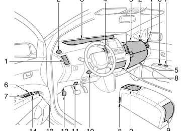
Climate remote control (steering pad switches)
D On humid days, do not blow cold air on the windshield. The windshield could fog up because of the difference in air temperature on the inside and outside of the windshield.
D Keep the area under the front seats clear to allow air to circulate through- out the vehicle.
27p104
for a minute
D On cold days, set the fan speed to high the intake ducts of snow or moisture. This can reduce the amount of fogging on the windows.
to help clear
D When driving on dusty roads, close all windows. If dust thrown up by the ve- hicle is still drawn into the vehicle after closing the windows, it is recommended that the air intake selector be set to OUTSIDE AIR and the fan speed se- lector to any setting except “OFFâ€.
D If following another vehicle on a dusty in windy and dusty road, or driving conditions, it is recommended that the air intake selector be temporarily set to RECIRCULATE, which will close off the outside passage and prevent outside air and dust from entering the vehicle interior.
The switches are installed on both sides of the steering pad. “A/C AUTO†switch: Use this switch to turn on the automatic mode. (For details, see page 182.) Pressing this switch in the automatic control turns the blower off. “ TEMP †switch: Use this switch to set the desired temperature. (For details, see page 182.) “ the air page 184.) †switch: Use this switch to remove “ interior fog on the windshield. (For details, see page 185.)
†switch: Use this switch to change intake mode. (For details, see
D The light sensor is located on the driv- er’s side edge of the instrument panel. If you put anything on this area or cover function may be adversely affected.
the sensor
the area,
D To cool off your Toyota after
it has been parked in the hot sun, drive with the windows open for a few minutes. This vents the hot air, allowing the air conditioning to cool the interior more quickly.
D Make sure the air intake grilles in front of the windshield are not blocked (by leaves or snow, for example).
186
“ †switch: Use this switch to turn on or off the rear window and outside rear view mirror defoggers. (For details, see page 110.)
CAUTION
Operate the switches with due care while you are driving to avoid acci- dents.
Instrument panel vents
27p006a
If air flow control is not satisfactory, check the instrument panel vents. The instrument panel vents may be opened or closed as shown.
187
188
SECTION 2– 10
OPERATION OF INSTRUMENTS AND CONTROLS Other equipment Clock Power outletss Rear console box Glove boxes Garage door opener Auxiliary boxes Cup holders Bottle holders Tie−down hooks Luggage storage box Luggage cover Floor mat
. . . . . . . . . . . . . . . . . . . . . . . . . . . . . . . . . . . . . . . . . . . . . . . . . . . . . . . . . . . . . . . . . . . . . . . . . . . . . . . . . . . . . . . . . . . . . . . . . . . . . . . . . . . . . . . . . . . . . . . . . . . . . . . . . . . . . . . . . . . . . . . . . . . . . . . . . . . . . . . . . . . . . . . . . . . . . . . . . . . . . . . . . . . . . . . . . . . . . . . . . . . . . . . . . . . . . . . . . . . . . . . . . . . . . . . . . . . . . . . . . . . . . . . . . . . . . . . . . . . . . . . . . . . . . . . . . . . . . . . . . . . . . . . . . . . . . . . . . . . . . . . . . . . . . . . . . . . . . . . . . . . . . . . . . . . . . . . . . . . . . . . . . . . . . . . . . . . . . . . . . . . . . . . . . . . . . . . . . . . . . . . . . . . . . . . . . . . . . . . . . . . . . . . . . . . . . . . . . . . . . . . . . . . . . . . . . . . . . . . . . . . . . . . . . . . . . . . . . . . . . . . . . . . . . . . . . . . . . . . . . . . . . . . . . . . . . . . . . . . . . . . . . . . . . . . . . . . . . . . . . . . . . . . . . . . . . . . . . . . . . . . . . .
190
190
191
191
192
195
196
196
197
197
198
199189
Clock
Power outlets
28p009d
28p010a
The power outlets are designed power supply for car accessories. The hybrid system must be in “ACC†or “IG−ON†for the power outlets to be used.
for
NOTICE
the
fuse
z To prevent
from being blown, do not use the electricity over the total vehicle capacity of 12V/120W.
The digital clock indicates the time. The hybrid system must be in “ACC†or “IG−ONâ€. To set the hour: Push the “H†button. To set the minutes: Push the “M†button. If the electrical power source has been disconnected from the clock, the time dis- play will automatically be set to 1:00 (one o’clock). When lights are turned on, the brightness of the time indi- cator will be reduced.
instrument panel
the
190
z To prevent the battery from being discharged, do not use the power outlet longer than necessary when the hybrid system is not operating. z Close the power outlet lid when the power outlet is not in use. Inserting anything other than an appropriate plug that fits the outlet, or allowing any into the outlet may cause electrical failure or short circuits.
liquid to get
Instrument panel
28p107
Rear console box
Rear console box
Glove boxes
28p012c
28p002a
To use the rear console box, open as shown in the illustration.
Upper glove box
CAUTION
When opening the rear console box, take due care not to catch your fin- gers.
28p105
Lower glove box
To open the glove boxes, push the each button. The inside of the upper glove box is sepa- rated by the partition. In case storing a longer object, remove the partition. With the instrument panel lights on, the lower glove box light will come on when the lower glove box is open.
CAUTION
To reduce the chance of in case of an accident or a sudden stop, always keep the glove box doors closed while driving.
injury
191
Garage door opener
Indicator light
28p108
Buttons
The garage door opener (HomeLinkR Universal Transceiver) is manufactured under license from HomeLinkR and can be programmed to operate garage doors, gates, entry doors, door locks, home lighting systems, and security systems, etc.
192
into
transmitter prior
(a) Programing the HomeLinkR The HomeLinkR in your vehicle has 3
buttons and you can store one program for each button. To ensure correct programing the HomeLinkR, install a new battery in the hand−held to program- ming. The battery side of the hand−held trans- mitter must be pointed away the HomeLinkR during the programming pro- cess. For Canadian users, follow the procedure “Programming an entrance gate/Pro- in gramming all devices the Canadian marketâ€. 1. Decide which of 3 HomeLinkR buttonsfrom
in
you want to program.
2. Place your hand−held garage transmit- ter 25 to 75 mm (1 to 3 in.) away from the surface of the HomeLinkR.
the
Keep HomeLinkR in view while programming.
light on
indicator
red
the
3. Simultaneously press and hold
the hand−held garage transmitter button along with the selected HomeLinkR but- ton.
4. When
the
indicator
the HomeLinkR changes from a slow to a rapid flash after 20 seconds, you can release both buttons.
light on
5. Test the operation of the HomeLinkR by pressing the newly programmed button. If programming a garage door opener, check to see if the garage door opens and closes.
(on
light
indicator
If the garage door does not operate, iden- tify if your garage transmitter is of the “Rolling Code†type. Press and hold the programmed HomeLinkR button. The ga- rage door has the rolling code feature if the the HomeLinkR) flashes rapidly and then remains lit after 2 seconds. If your garage transmitter is the “Rolling Code†type, proceed to the heading “Programming a rolling code sys- temâ€. 6. Repeat steps 2 through 5 for each re- maining HomeLinkR button to program another device.
it
is
to
is necessary
Programming a rolling code system “Rolling Code†If your device follow equipped, steps 1 through 4 under the heading “Programming the HomeLinkR†before proceeding with the steps listed below. 1. Locate the “training†button on the ceil- ing mounted garage door opener motor. The exact the button may vary by brand of garage door opener. Refer the owner’s guide supplied by the garage door opener manufacturer for the location of this “training†button.
location and color of
to
2. Press the “training†button on the ceil- ing mounted garage door opener motor. Following this step, you have 30 seconds in which to initiate step 3 below. 3. Press and release the vehicle’s pro- grammed HomeLinkR button twice. The garage door may open. the door does open, the programming process is complete. If the door does not open, press and release the button a third time. This third press and release will complete the programming process by opening the garage door.
If
now
should
recognize
The ceiling mounted garage door opener motor the HomeLinkR unit and be able activate the garage door up/down. 4. Repeat steps 1 through 3 each remain- to program
ing HomeLinkR button another rolling code system.
Programming an entrance gate/Program- ming all devices in the Canadian market 1. Decide which of the 3 HomeLinkR but-
2. Place
your
tons you want to program. hand−held
gate/device transmitter 25 to 75 mm (1 to 3 in.) away the HomeLinkR.
surface
from
the
of
Keep the indicator light on the HomeLinkR in view while programming. 3. Press
selected
hold
and
the
HomeLinkR button.
4. Continuously press and release (cycle) transmitter the hand−held gate/device button every two seconds until step 5
is complete. thethe HomeLinkR changes from a slow to a rapid flash after 20 seconds, you can release both buttons.
light on
5. When
indicator
6. Test the operation of the HomeLinkR by pressing the newly programmed button. Check to see if the gate/device oper- ates correctly.
7. Repeat steps 1 through 6 for each re- maining HomeLinkR button to program another device.
Programming other devices To program other devices such as home security systems, home door locks or lighting, contact your authorized Toyota dealer for assistance. Reprogramming a button Individual HomeLinkR buttons cannot be erased, however, to reprogram a single button, follow the procedure “Programming the HomeLinkRâ€. (b) Operating the HomeLinkR To operate the HomeLinkR, press the ap- propriate HomeLinkR button to activate the programmed device. The HomeLinkR indi- cator The HomeLinkR continues to send the signal for up to 20 seconds as long as the but- ton is pressed.
should
come
light
on.
193
following
This device complies with part 15 of the FCC Rules and with RSS−210 of the Industry Canada. Operation is subject to the two conditions: (1) This device may not cause harmful interfer- ence, and (2) this device must accept any interference that may be received, including that may cause undesired operation. WARNING: This transmitter has been tested and complies with FCC and Industry Canada DOC/MPAC rules. Changes or modifications not ex- pressly approved by the party respon- sible for compliance could void the user’s authority to operate the device.
interference
CAUTION
D When programming the HomeLinkR Universal Transceiver, you may be operating a garage door or other device. Make sure people and ob- jects are out of the way of the ga- rage door or other device to pre- vent potential harm or damage.
D Do not use this HomeLinkR Univer- sal Transceiver with any garage door opener that lacks the safety stop and reverse feature as re- quired by federal safety standards. (This includes any garage door opener model manufactured before April 1, 1982.) A garage door open- er which cannot detect an object (signaling the door to stop and re- verse), does not meet current feder- al safety standards. Using a garage door opener without these features increases risk of serious injury or death.
(c) Erasing
the
entire HomeLinkR
memory (all three programs)
To erase all previously programmed codes at one time, press and hold down the 2
outside buttons for 20 seconds until the indicator light flashes. If you sell your vehicle, be sure to erase the programs stored the HomeLinkR memory.in
194
Auxiliary boxes To use the box, open the lid as shown in the following illustrations.
CAUTION
D To reduce the chance of injury in case of an accident or a sudden stop, always keep the auxiliary box closed while driving.
D Auxiliary box on the ceiling—
As this box is designed for holding a light object such as an eyeglass, do not place any heavy objects in it. Heavy objects may cause the holder to open and contents to fly out resulting in injuries.
NOTICE
Auxiliary box on the ceiling— In hot weather, inside of the vehicle ceiling becomes very hot. Do not leave anything flammable or deform- able such as a lighter, the glasses, etc. inside.
28p117
28p003a
Front ceiling
On the instrument panel
28p011c
28p111
Front side of the console box
Left side of the luggage compartment
195
Cup holders
Bottle holders
The cup holder is designed for holding cups or drink−cans securely. To use the cup holder, open the lid.
CAUTION
D Do not place anything else other than cups or drink−cans on the cup items may be holder, as such thrown about in the compartment and possibly injure people in the vehicle during sudden braking or in an accident.
D To reduce the chance of injury in case of an accident or a sudden stop while driving, keep the cup holder closed when not in use.
D Take due care not to catch your is
the cup holder
fingers when opened.
28p109
The bottle holders are designed to hold bottles securely.
CAUTION
Do not attempt to use the holder for any other purpose for which it was intended. Inappropriately sized or shaped objects may be thrown about in the compartment and possibly in- jure people in the vehicle during a sudden braking or an accident.
28p005b
For front seats
28p006b
For rear seats
196
NOTICE
Do not put a cup or open bottle in the bottle holder because the con- tents may spill when the door opens or closes.
Tie−down hooks
Luggage storage box
22p120
28p112a
1. To open the luggage storage box, turn the knob to the “UNLOCK†position and open the lid.
To secure your luggage, use the tie− down hooks as shown above. See “—Stowing precautions†on page 224
for precautions when loading luggage.CAUTION
To avoid personal injury, keep the tie− down hooks retracted when not in use.
197
Luggage cover
28p113a
28p114
28p115
2. Hold the lid open by inserting the sup-
port rod into the slot.
To use the luggage cover, pull it out of the retractor and hook it on the an- chors.
To remove the luggage cover, lift it up.
CAUTION
To reduce the chance of in case of an accident or a sudden stop, keep the luggage storage box closed and locked while driving.
injury
CAUTION
Do not place anything on the luggage cover. Such thrown away and possibly injure people in the vehicle during sudden braking or a collision.
items may be
198
Floor mat
28p116a
28p125
28p007b
in
the
that
time, adjust
the cover so
You can stow the luggage cover in the luggage storage box luggage compartment as shown in the illustration. At that “TOP†is facing up. After removing the luggage cover, stow it the luggage storage box or place it in somewhere other the passenger compartment. This will prevent passengers from being injured in the event of a sud- den stop or accident.
than
To replace the luggage cover, adjust the cover so that “TOP†is facing upwards.
Use a floor mat of the correct size. If the floor carpet and floor mat have 2
holes, then they are designed for use with locking clips. Fix the floor mat with lock- ing clips into the holes in the floor carpet.199
28p008b
CAUTION
Make sure the floor mat is properly placed on the floor carpet. If the floor mat slips and the movement of the pedals during driv- ing, it may cause an accident.
interferes with
200
SECTION 3
INFORMATION BEFORE DRIVING YOUR TOYOTA INFORMATION BEFORE DRIVING YOUR TOYOTA Break−in period . . . . . . . . . . . . . . . . . . . . . . . . . . . . . . . . . . . . . . . . . . . . . . . . . . . . . . . . . . . . . . . . . . . . . . . . . . . . . . . . . . . . . . . . . . . . . . . . . . . Fuel . . . . . . . . . . . . . . . . . . . . . . . . . . . . . . . . Fuel pump shut−off systemm Operation in foreign countries . . . . . . . . . . . . . . . . . . . . . . . . . . . . . . . . . . . . . . . . . . . . . . . . . . . . . . . . . . . . . . Three−way catalytic converters . . . . . . . . . . . . . . . . . . . . . . . . . . . . . . . . . . . . Engine exhaust cautions . . . . . . . . . . . . . . . . . . . . . . . . . . Facts about engine oil consumption Coolant heat storage system . . . . . . . . . . . . . . . . . . . . . . . . . . . . . . . . . Iridium−tipped spark plugs . . . . . . . . . . . . . . . . . . . . . . . . . . . . . . . . . . . . . . . . . . . . . . . . . . . . . . . . . . . . . . . . . . . . . . . . . . . . . . . . . Brake system . . . . . . . . . . . . . . . . . . . . . . . . . . . . . . . Electric power steering system Brake pad wear limit indicators . . . . . . . . . . . . . . . . . . . . . . . . . . . . . . . Your Toyota’s identification . . . . . . . . . . . . . . . . . . . . . . . . . . . . . . . . . . . . . . . . . . . . . . . . . . . . . . . . . . . . . . . . . . . . . . . . Theft prevention labels Suspension and chassis . . . . . . . . . . . . . . . . . . . . . . . . . . . . . . . . . . . . . . . . . . . . . . . . . . . . . . . . . . . . . . . . . . . . . . . . . . . . . . . . . Tire information . . . . . . . . . . . . . . . . . . . . . . . . . . . . . . . . . . . . . . . . . . Vehicle load limits . . . . . . . . . . . . . . . . . . . . . . . . . . . . . . . . . . . . . . . . . Cargo and luggage Types of tires . . . . . . . . . . . . . . . . . . . . . . . . . . . . . . . . . . . . . . . . . . . . . . .
202
202
204
204
205
206
206
208
208
209
213
213
214
215
215
216
224
224
227201
Break−in period Drive gently and avoid high speeds. Your vehicle does not need an elaborate break−in. But following a few simple tips for the first 1000 km (600 miles) can add to the future economy and long life of your vehicle: D Avoid
full−throttle acceleration when
starting and driving.
D Avoid racing the hybrid engine. D Try to avoid hard stops during the first
300 km (200 miles).
Fuel FUEL TYPE Your vehicle must use only unleaded gasoline. To help prevent gas station mixups, your Toyota has a smaller fuel tank opening. The special nozzle on pumps with un- leaded fuel will fit it, but the larger stan- dard nozzle on pumps with leaded gas will not. At a minimum, the gasoline you use should meet the specifications of ASTM D4814 in the U.S.A. and CGSB 3.5−M93
in Canada.NOTICE
Do not use leaded gasoline. Use of leaded gasoline will cause the three− way catalytic converter to lose its ef- fectiveness and the emission control system to function improperly. Also, this can increase maintenance costs.
OCTANE RATING Select unleaded gasoline with an Oc- tane Rating of 87 (Research Octane Number 91) or higher.
202
fuel, or
the recommended
Use of unleaded fuel with an octane num- ber or rating lower than stated above will cause persistent heavy knocking. If se- vere, this will lead to engine damage. If your engine knocks... If you detect heavy knocking even when using if you hear steady knocking while holding a steady speed on level roads, consult your Toyota dealer. However, occasionally, you may notice light knocking for a short time while accel- erating or driving up hills. This is normal and there is no need for concern. GASOLINE CONTAINING DETERGENT ADDITIVES Toyota recommends the use of gasoline that contains detergent additives to avoid build−up of engine deposits. However, all gasoline sold the U.S. contains detergent additives to keep clean and/or clean intake systems.
in
for quality
QUALITY GASOLINE Automotive manufacturers in the U.S., Europe and Japan have developed a specification fuel named World−Wide Fuel Charter (WWFC) that is expected to be applied world wide. The WWFC consists of four categories that depend on required emission le- vels. In the U.S., category 4 has been adopted. The WWFC improves air quali- ty by providing for better emissions in vehicle fleets, and customer satisfaction through better vehicle performance. CLEANER BURNING GASOLINE Cleaner burning gasoline, including re- formulated gasoline that contains oxy- genates such as ethanol or MTBE is available in many areas. Toyota recommends the use of cleaner burning gasoline and appropriately blended reformulated gasoline. These types of gas- oline provide excellent vehicle perfor- mance, reduce vehicle emissions, and im- prove air quality.
If you use gasohol
OXYGENATES IN GASOLINE Toyota allows the use of oxygenate blended gasoline where the oxygenate content is up to 10% ethanol or 15% MTBE. in your Toyota, be sure that it has an octane rating no lower than 87. Toyota does not recommend the use of gasoline containing methanol. GASOLINE CONTAINING MMT Some gasoline contain an octane en- hancing additive called MMT (Methylcy- clopentadienyl Manganese Tricarbonyl). Toyota does not recommend the use of gasoline that contains MMT. If fuel con- taining MMT is used, your emission con- trol system may be adversely affected. The Malfunction Indicator Lamp on the in- strument cluster may come on. If this hap- pens, contact your Toyota dealer for ser- vice.
GASOLINE QUALITY In a very few cases, you may experience driveability problems caused by the partic- ular gasoline that you are using. If you continue to have unacceptable driveability, try changing gasoline brands. If this does not rectify your problem, then consult your Toyota dealer.
NOTICE
z Do not use gasohol other
than stated above. It will cause fuel sys- tem damage or vehicle performance problems.
z If drivability problems are encoun- tered (poor hot starting, vaporizing, engine knock, etc.), discontinue its use.
z Take care not to spill gasohol dur- ing refueling. Gasohol may cause paint damage.
203
FUEL TANK CAPACITY
45 L (11.9 gal., 9.9 lmp. gal.)
is approved
The given fuel tank capacity is measured testing condition on EPA/CARB ORVR which for nominal capacity measurement condition. The fuel tank capacity is decreased at low ambient temperature. (decreased by about 5 L (1.3 gal., 1.1 lmp. gal.) at −10_C (14_F).)
Fuel pump shut−off system The fuel pump shut−off system stops sup- plying fuel to the engine to minimize the risk of fuel leakage when the engine stalls or an airbag inflates upon collision. To restart the hybrid system after the fuel pump shut−off system activates, press the “POWER†switch to the “OFF†mode and start it.
CAUTION
Inspect the ground under the vehicle before restarting the hybrid system. If you find that liquid has leaked onto the ground, the fuel system has been damaged and it is in need of repair. In this case, do not restart the hybrid system.
Operation in foreign countries If you plan to drive your Toyota another country... First, comply with the vehicle registration laws. Second, confirm the availability of the cor- rect fuel (unleaded and minimum octane number).
in
204
Three−way catalytic converters
30p001d
The three−way catalytic converters are emission control devices in the exhaust system. Its purpose is to reduce pollutants in the exhaust gas.
installed
CAUTION
D Keep people and combustible mate- rials away from the exhaust pipe while the engine is running. The exhaust gas is very hot.
D Do not drive, idle or park your ve- hicle over anything that might burn easily such as grass, leaves, paper or rags.
NOTICE
large amount of unburned gases into the three−way catalytic flowing converter may cause it to overheat and create a fire hazard. To prevent this and other damage, observe the following precautions: z Use only unleaded gasoline. z Do not drive with an extremely low fuel level; running out of fuel could cause the engine to misfire, creat- ing an excessive load on the three− way catalytic converter.
z Do not turn off the ignition while
the vehicle is moving.
z Keep your engine in good running order. Malfunctions in the engine electrical system, electronic ignition system/distributor ignition system or fuel system could cause an ex- tremely high temperature.
z If the engine becomes difficult to start or stalls frequently, take your vehicle in for a check−up as soon as possible. Remember, your Toyota dealer knows your vehicle and its three−way catalytic converter sys- tem best.
z To ensure that the three−way cata- lytic converter and the entire emis- sion control system operate proper- ly, your vehicle must receive the periodic inspections required by the Toyota Maintenance Schedule. For scheduled maintenance information, refer to the “Scheduled Maintenance Guide†or “Owner’s Manual Supple- mentâ€.
205
Engine exhaust cautions
CAUTION
D Avoid inhaling the engine exhaust. It contains carbon monoxide, which is a colorless and odorless gas. It can cause unconsciousness or even death.
D Make sure the exhaust system has no holes or loose connections. The system should be checked from time to time. If you hit something, or notice a change in the sound of the the system exhaust, have checked immediately.
D Do not run the hybrid system in a garage or enclosed area except for the time needed to drive the vehicle in or out. The exhaust gases cannot escape, making this a particularly dangerous situation.
D Keep the back door closed while driving. An open or unsealed back door may cause exhaust gases to be drawn into the vehicle.
D To allow proper operation of your vehicle’s ventilation system, keep the inlet grilles in front of the wind- shield clear of snow, leaves, or oth- er obstructions.
D If you smell exhaust fumes in the the windows vehicle, drive with the back door closed. open and Have the cause immediately located and corrected.
D Do not remain for a long time in a parked vehicle with the hybrid sys- tem running. is unavoidable, however, do so only in an uncon- fined area and adjust the heating or cooling system to force outside air into the vehicle.
If
it
206
Facts about engine oil consumption FUNCTIONS OF ENGINE OIL Engine oil has the primary functions of lubricating and cooling the inside of the engine, and plays a major role in main- taining the engine in proper working order. ENGINE OIL CONSUMPTION It is normal that an engine should con- sume some engine oil during normal engine operation. The causes of oil consumption in a normal engine are as follows. D Oil is used to lubricate pistons, piston rings and cylinders. A thin film of oil is the cylinder wall when a piston moves downwards in the cylin- der. High negative pressure generated when the vehicle is decelerating sucks some of this oil into the combustion chamber. This oil as well as some part of the oil film left on the cylinder wall is burned by the high temperature com- bustion gases during the combustion process.
left on
D Oil is also used to lubricate the stems of the intake valves. Some of this oil is sucked into the combustion chamber together with is burned along with the fuel. High tem- perature exhaust gases also burn the oil used to lubricate the exhaust valve stems.
intake air and
the
The amount of engine oil consumed de- pends on the viscosity of the oil, the quality of the oil and the conditions the vehicle is driven under. More oil is consumed by high−speed driv- ing and frequent acceleration and decel- eration. A new engine consumes more oil, since its pistons, piston rings and cylinder walls have not become conditioned. Oil consumption: Max. 1.0 L per 1000
km Imp.qt./600
miles) When judging the amount of oil con- sumption, note that the oil may become diluted and make it difficult to judge the true level accurately.(1.1 qt./600 miles, 0.9
For detailed information on oil level check, see “Checking level†on page 282.
the engine oil
As an example, if a vehicle is used for repeated short trips, and consumes a nor- mal amount of oil, the dipstick may not show any drop in the oil level at all, even after 1000 km (600 miles) or more. This is because the oil is gradually becoming diluted with fuel or moisture, making it appear that the oil level has not changed. The diluting ingredients evaporate out when the vehicle is then driven at high speeds, as on an expressway, making it appear that oil is excessively consumed after driving at high speeds. IMPORTANCE OF ENGINE OIL LEVEL CHECK One of the most important points in prop- er vehicle maintenance is to keep the en- gine oil at the optimum level so that oil function will not be impaired. Therefore, it is essential that the oil level be checked regularly. Toyota recommends that the oil level be checked every time you refuel the vehicle.
NOTICE
Failure to check the oil level regularly could lead to serious engine trouble due to insufficient oil.
207
Coolant heat storage system
Iridium−tipped spark plugs
CAUTION
Coolant flow control valve
30p103
Electric water pump Coolant heat storage
tank
The coolant heat storage tank system stores hot coolant and feeds it via the electric water pump automatically to warm the engine as required. This system helps generate clean emissions. To confirm the coolant heat storage system check, the pump may operate automatically with the vehicle stopped (in the “IG−OFF†mode). Although the pump may operate and cause noise while the vehicle is stopped, this does not indicate a malfunction.
208
D The coolant in this tank is hot even if the engine and radiator are cold. the coolant,
replacement of
D For
contact your Toyota dealer.
D Do not
touch bolts
painted in yellow.
(9 pieces)
D In case
the bolts are
loosened, there is a risk of hot coolant com- ing out from inside the tank.
D When this has any malfunction, the surface of this tank gets hot. To prevent burning yourself, do not touch the tank.
INFORMATION
D In such cases as the time of engine starting and a short trip after the engine is stopped, the electric water pump will work for a moment, but this is no problem.
D This is for the preparation for good
emission.
Your engine is fitted with iridium−tipped spark plugs.
NOTICE
Use only iridium−tipped spark plugs and do not adjust gaps for your en- gine performance and smooth drivabil- ity.
Brake system REGENERATIVE BRAKE When the brake is applied, the electric motor used as a generator converts kinet- ic energy into electric energy. The regenerative brake works in the fol- lowing operations. 1. When
the accelerator pedal
re- leased, the reduced speed equal to en- gine braking in a gasoline−fueled ve- hicle is obtained in accordance with the running mode position of the shift le- ver.
is
2. When
the brake pedal
is depressed with the shift lever in “D†or “Bâ€, the regenerative brake works.
HYDRAULIC BRAKE This brake system has 3 independent hy- draulic circuits. If either circuit should fail, the other will still work. However, the ped- al will be harder to press, and your stop- ping distance will the brake system warning light may come on.
increase. Also,
CAUTION
Do not drive your vehicle with only a single brake system. Have your brakes fixed immediately.
the brake system warning
BRAKE ACTUATOR The brake actuator uses brake fluid pres- surized by the pump to power−assist the brakes. If the brake actuator fails during driving, light comes on and buzzer sounds continuous- ly. In this case, the brakes may not work properly. If they do not work well, depress the brake pedal firmly. If the brake system warning light comes on, immediately stop your vehicle and contact your Toyota deal- er.
the brake pedal
The yellow brake system warning light may stay on for about 60 seconds after the “IG−ON†mode is enabled. It is normal if the light turns off after a while. Depressing repeatedly may turn on the red brake system warning light and buzzer. It is normal if the light turns off and the buzzer stops sounding after a few seconds. You may hear a small sound in the engine compartment after is started or the brake pedal is depressed repeatedly. This is a pump pulsating sound of the brake system, and it is not a malfunction. In the following conditions, you may hear a motor sound in the engine compartment. D The brake pedal is depressed when the
the hybrid system
hybrid system is turned off. D The driver’s door is opened. D For a
few seconds after
the hybrid system is “OFF†and about 90 seconds have passed.
The brake pedal stroke may be short when you press the “POWER†switch with the brake pedal depressed.
209
CAUTION
D Even if the power assist
D Do not pump the brake pedal if the hybrid system is not operating. Each push on the pedal uses up your reserved brake fluid pressure. is com- pletely the brakes will still work. But you will have to push the pedal hard, much harder than nor- mal. And your braking distance will increase.
lost,
Depressing the brake pedal on slippery road surfaces such as on a manhole cov- er, a steel plate at a construction site, joints in a bridge, etc. on a rainy day tends to activate the anti−lock brake sys- tem. When the anti−lock brake system is ac- tivated, the following condition may oc- cur. They do not indicate a malfunction of the system: D You may hear the anti−lock brake sys- tem operating and the vibrations of the vehicle body and steering wheel. You may also hear the motor sound in the engine compartment even after the ve- hicle is stopped.
ANTI−LOCK BRAKE SYSTEM The anti−lock brake system is designed to automatically help prevent lock−up of the wheels during a sudden braking or braking on slippery road surfaces. This assists in providing directional stability and steering performance of the vehicle under these circumstances.
Effective way to press the ABS brake pedal: When the anti−lock brake system function is in action, the slip indicator in the instrument cluster flashes and you will hear a noise. In this situation, to let the anti−lock brake system work for you, just hold the brake pedal down more firmly. Do not pump the brake in a panic stop. This will result in reduced braking performance.
The anti−lock brake system becomes op- erative after the vehicle has accelerated to a speed in excess of approximately 10
km/h (6 mph). It stops operating when the vehicle decelerates to a speed below approximately 5 km/h (3 mph).210
CAUTION
Do not overestimate the anti−lock brake system: Although the anti−lock brake system assists in providing ve- hicle control, it is still important to drive with all due care and maintain a moderate speed and safe distance from the vehicle in front of you, be- cause there are limits to the vehicle stability and effectiveness of steering wheel operation even with the anti− lock brake system on. If tire grip performance exceeds its capability, or if hydroplaning occurs during high speed driving in the rain, the anti−lock brake system does not provide vehicle control.
the vehicle
Anti−lock brake system is not de- signed to shorten the stopping dis- tance: Always drive at a moderate speed and maintain a safe distance from front of you. Compared with vehicles without an anti−lock brake system, your vehicle may require a longer stopping dis- tance in the following cases: D Driving on rough, gravel or snow−
in
covered roads.
D Driving with tire chains installed. D Driving over the steps such as the
joints on the road.
D Driving on roads where the road surface is pitted or has other differ- ences in surface height.
Install all 4 tires of specified size at appropriate pressure: The anti−lock brake system detects vehicle speeds using the speed sensors for respec- tive wheels’ turning speeds. The use of tires other than specified may fail to detect the accurate turning speed, resulting longer stopping dis- tance.
in a
30p002b
Vehicle sold in U.S.A.
30p007b
Vehicle sold in Canada
211
A warning light turning on briefly during operation does not indicate a problem.
CAUTION
If the “ABS†warning light remains on together with the red brake system warning light, immediately stop your vehicle at a safe place and contact your Toyota dealer. In this case, not only the anti−lock brake system will fail but also the vehicle will become extremely unsta- ble during braking.
Either of the following conditions may occur, but does not indicate a malfunc- tion: D The light may stay on for about 60
seconds after the “IG−ON†mode is en- abled. It is normal if it turns off after a while.D Depressing the brake pedal repeatedly may turn on the light. It is normal if it turns off after a few seconds.
the brakes on,
BRAKE ASSIST SYSTEM When you slam the brake assist system judges as an emer- gency stop and provides more powerful braking for a driver who cannot hold down the brake pedal firmly. When you slam the brakes on, more pow- erful braking will be applied. At this time, the engine you may hear a sound in compartment. This does not indicate a malfunction. The brake assist system becomes opera- tive after the vehicle has accelerated to a speed in excess of approximately 10
km/h (6 mph). It stops operating when the vehicle decelerates to a speed below approximately 5 km/h (3 mph). For an explanation of this system’s warn- ing light, see “Service reminder indicators and warning buzzers†on page 117.“ABS†warning light The light comes on when the “IG−ON†mode is enabled. If the anti−lock brake system works properly, the light turns off after the “READY†light comes on. Thereafter, if the system malfunctions, the light comes on again. When the “ABS†warning light is on (and the brake system warning light is off), the anti−lock brake system does not operate, but the brake system still operates con- ventionally. When the “ABS†warning light is on (and the brake system warning light is off), the anti−lock brake system does not operate so that the wheels could lock up during a sudden braking or braking on slippery road surfaces. If either of the following conditions oc- curs, this indicates a malfunction some- where in the components monitored by the warning light system. Contact your Toyota dealer as soon as possible to service the vehicle. D The light does not come on when the the
is enabled, or
“IG−ON†mode “READY†light remains on.
D The light comes on while you are driv-
ing.
212
Electric power steering system The electric power steering system, us- ing an electric motor, assists the turn- ing of the steering wheel. In the following cases, you may feel the steering becomes heavy. However, the electric power steering system warning light does not come on. (Because it is not a malfunction.) D When maneuvering
the steering
fre- quently or keeping the steering wheel turned fully while the vehicle is stopped or moving very slowly