- 2009 Toyota 4runner Owners Manuals
- Toyota 4runner Owners Manuals
- 2005 Toyota 4runner Owners Manuals
- Toyota 4runner Owners Manuals
- 2002 Toyota 4runner Owners Manuals
- Toyota 4runner Owners Manuals
- 2010 Toyota 4runner Owners Manuals
- Toyota 4runner Owners Manuals
- 2012 Toyota 4runner Owners Manuals
- Toyota 4runner Owners Manuals
- 2001 Toyota 4runner Owners Manuals
- Toyota 4runner Owners Manuals
- 2015 Toyota 4runner Owners Manuals
- Toyota 4runner Owners Manuals
- 2006 Toyota 4runner Owners Manuals
- Toyota 4runner Owners Manuals
- 2004 Toyota 4runner Owners Manuals
- Toyota 4runner Owners Manuals
- 2003 Toyota 4runner Owners Manuals
- Toyota 4runner Owners Manuals
- 2008 Toyota 4runner Owners Manuals
- Toyota 4runner Owners Manuals
- 2014 Toyota 4runner Owners Manuals
- Toyota 4runner Owners Manuals
- 2000 Toyota 4runner Owners Manuals
- Toyota 4runner Owners Manuals
- 2011 Toyota 4runner Owners Manuals
- Toyota 4runner Owners Manuals
- 2007 Toyota 4runner Owners Manuals
- Toyota 4runner Owners Manuals
- Download PDF Manual
-
the
filter
from
the
filter
5. Inspect the filter on the surface. If it is the just moderately dusty, it may be cleaned by blowing compressed air from the reverse surface. Do not wash or oil the filter. If it is dirty, it should be replaced. When setting the filter to the filter case, ensure that the flat side of the filter is down and the ribbed side is up. Position the filter case so that the “↑UP” mark is pointing up and install it in the vehicle.
369
2004 4RUNNER from Sep. ’04 Prod. (OM35847U)
’04 4Runner_U (L/O 0409)
Checking tire inflation pressure
Keep your tire inflation pressures at the proper level. The recommended cold tire inflation pressures, tire sizes and the com- bined weight of occupants and cargo (vehicle capacity weight) are de- scribed on page 392 and 396. They are also on the tire and loading infor- mation label. You should check the tire inflation pressure every two weeks, or at least once a month. And do not forget the spare! The for checking tire inflation pressure should be observed: (cid:1) The
instructions
be checked only when the tires are cold. If your vehicle has been parked for at least 3 hours and has not been driven for more than 1.5
km or 1 mile since, you will get an accurate cold tire inflation pres- sure reading.following
pressure
should
(cid:1) If you cannot adjust the tire pressure when the tires are cold, add 20 to 30 kPa more to the front tires and rear tires than the cold tire pressure, but never exceed the maximum cold tire pressure molded on the tire side- wall.
(cid:1) Always use a tire pressure gauge. The appearance of a tire can be misleading. Besides, tire inflation pressures that are even just a few pounds off can degrade ride and handling.
(cid:1) Do not bleed or reduce tire inflation pressure after driving. It is normal for the tire inflation pressure to be higher after driving. (cid:1) Never exceed the vehicle capac- ity weight. Passenger and lug- gage weight should be located so that the vehicle is balanced.
2004 4RUNNER from Sep. ’04 Prod. (OM35847U)
370
’04 4Runner_U (L/O 0409)
Tire pressure gauge
INSPECTION AND ADJUSTMENT PROCEDURE 1. Remove the tire valve cap. 2. Press the tip of the tire pressure
gauge to the tire valve.
3. Read the pressure using the grad-
uations of the gauge.
4. In case the tire inflation pressure is not within the prescribed range, insert the compressed air from the valve. In case of applying too much air, press the center of the valve and release the air to adjust.
5. After completing the tire inflation pressure measurement and ad- justment, apply soapy water to the valve and check for leakage.
6. Install the tire valve cap. If a gauge and air pump are not avail- able, have your vehicle checked by your Toyota dealer.
CAUTION
Be sure to reinstall the tire valve caps. Without the valve caps, dirt or moisture could get into the valve core and cause air leakage. If the caps have been lost, have new ones put on as soon as pos- sible.
NOTICE
Use only the original valve cap. If any other valve cap is used, it may corrode or melt and be- come difficult or impossible to remove.
Incorrect tire inflation pressure may waste fuel, reduce the comfort of driv- ing, reduce tire life and make your ve- hicle less safe to drive. If a tire frequently needs refilling, have it checked by your Toyota deal- er.
CAUTION
Keep your tires properly inflated. Otherwise, the following condi- tions may occur and cause an ac- cident resulting in death or seri- ous injuries. Low tire pressure (underinfla- tion)— (cid:1) Excessive wear (cid:1) Uneven wear (cid:1) Poor handling (cid:1) Possibility of blowouts from an
overheated tire
(cid:1) Poor sealing of the tire bead
371
2004 4RUNNER from Sep. ’04 Prod. (OM35847U)
(cid:1) Wheel deformation and/or tire
separation
(cid:1) A greater possibility of tire
damage from road hazards
High tire pressure (overinfla- tion)— (cid:1) Poor handling (cid:1) Excessive wear (cid:1) Uneven wear (cid:1) A greater possibility of tire
damage from road hazards
372
’04 4Runner_U (L/O 0409)
Checking and replacing tires
Tread wear indicator
CHECKING YOUR TIRES Check the tire’s tread for tread wear indicators. If the indicators show, replace the tires. The loca- tion of tread wear indicators is shown by the “TWI” or “D ” marks, etc., molded on the sidewall of each tire.
The tires on your Toyota have built- in tread wear indicators to help you know when the tires need replace- ment. When the tread depth wears to 1.6 mm (0.06 in.) or less, the indica- tors will appear. If you can see the indicators in two or more adjacent grooves, the tire should be replaced. The lower the tread, the higher the risk of skidding. The effectiveness of snow tires is lost if the tread wears down below 4 mm (0.16 in.). If you have tire damage such as cuts, splits, cracks deep enough to expose the fabric, or bulges indi- cating internal damage, the tire should be replaced. If a tire often goes flat or cannot be properly repaired due to the size or location of a cut or other damage, it should be replaced. If you are not sure, consult with your Toyota dealer.
2004 4RUNNER from Sep. ’04 Prod. (OM35847U)
If air loss occurs while driving, do not continue driving. Driving even a short distance can damage a tire beyond repair. Any tires which are over 6 years old must be checked by a qualified technician even if damage is not obvious. Tires deteriorate with age even if they have never or seldom been used. This applies also to the spare tire and tires stored for future use.
’04 4Runner_U (L/O 0409)
For details about the side wall of the tire and the Certification Label, see pages 283 and 286.
CAUTION
Observe the following instruc- tions. Otherwise, an accident may occur resulting in death or serious injuries. (cid:1) Do not mix radial, bias belted, or bias- ply tires on your ve- hicle, as this may cause dan- gerous handling characteris- tics resulting in loss of control. (cid:1) Do not use tires other than the manufacturer’s recommended size, as this may cause danger- ous handling characteristics resulting in loss of control.
REPLACING YOUR TIRES When replacing a tire, use a tire of the same size and construction, and the same or greater maximum load as the originally installed tires. Also, on four- wheel drive models, all the tires must be the same brand and have the same tread patterns. Using any other size or type of tire may seriously affect handling, ride, speedometer/odometer calibration, ground clearance, and clearance be- tween the body and tires or snow chains. Check that the maximum load of the replaced tire is greater than 1/2 of the Gross Axle Weight Ratings (GAWR) of either the front axle or the rear axle, whichever is greater. As for the maximum load of the tire, see the load limit at maximum cold tire inflation pressure mentioned on the sidewall of the tire, and as for the Gross Axle Weight Ratings (GAWR), see the Cer- tification Label.
373
2004 4RUNNER from Sep. ’04 Prod. (OM35847U)
’04 4Runner_U (L/O 0409)
Rotating tires
When rotating tires, check for uneven wear and damage. Abnormal wear is usually caused by incorrect tire pres- sure, improper wheel alignment, out- of- balance wheels, or severe braking.
(cid:1) Four- wheel drive models:
Do not use tires of different brands, sizes, construction or tread patterns, as this may cause dangerous handling characteristics in loss of control.
resulting
Toyota recommends all four tires, or at least both of the front or rear tires be replaced at a time as a set. See “If you have a flat tire” on page 323 for tire change procedure. When a tire is replaced, the wheel should always be balanced. An unbalanced wheel may affect ve- hicle handling and tire life. Wheels can get out of balance with regular use and should therefore be balanced occasionally. When replacing a tubeless tire, the air valve should also be replaced with a new one.
374
To equalize the wear and help ex- tend tire life, Toyota recommends that you rotate your tires accord- ing to the maintenance schedule. (For scheduled maintenance infor- mation, please refer to the “Sched- uled Maintenance Guide” or “Own- er’s Supplement”.) However, the most appropriate tim- ing for tire rotation may vary ac- cording to your driving habits and road surface conditions. See “If you have a flat tire” on page 323 in Section 4 for tire change proce- dure.
Manual
2004 4RUNNER from Sep. ’04 Prod. (OM35847U)
’04 4Runner_U (L/O 0409)
Installing snow tires and chains WHEN TO USE SNOW TIRES OR CHAINS Snow tires or chains are recommended when driving on snow or ice. On wet or dry roads, conventional tires provide better traction than snow tires. SNOW TIRE SELECTION If you need snow tires, select tires of the same size, construction and load capacity as the originally installed tires. Also, on four- wheel drive models, all the tires must be the same brand and have the same tread patterns. Do not use tires other than those men- tioned above. Do not install studded tires without first checking local regulations for possible restrictions.
CAUTION
the
following
Observe instructions. Otherwise, an accident may occur re- sulting in death or serious injuries. (cid:1) Do not use snow tires other than the manufacturer’s recommended si- ze, as this may cause dangerous handling characteristics resulting in loss of control.
(cid:1) Four- wheel drive models:
Do not use snow tires of different brands, sizes, construction or tread patterns, as this may cause danger- ous handling characteristics result- ing in loss of control.
SNOW TIRE INSTALLATION Snow tires should be installed on all wheels. Installing snow tires on the front wheels only can lead to an excessive difference in road grip capability between the front and rear tires which could cause loss of vehicle control. When storing removed tires, you should store them in a cool dry place. Mark the direction of rotation and be sure to install them in the same direction when replacing.
CAUTION
(cid:1) Do not drive with the snow tires
incorrectly inflated.
(cid:1) Never drive over 120 km/h (75 mph)
with any type of snow tires.
TIRE CHAIN SELECTION Use the tire chains of correct size. Regulations regarding the use of tire chains vary according to location or type of road, so always check local reg- ulations before installing chains. CHAIN INSTALLATION Install the chains on the rear tires as tightly as possible. Do not use tire tires. Retighten chains on chains after km (1/4—1/2 mile). When installing chains on your tires, care- fully follow the instructions of the chain manufacturer. If wheel covers are used, they will be scratched by the chain band, so remove the covers before putting on the chains.
front driving
0.5—1.0
the
CAUTION
(cid:1) Do not exceed 50 km/h (30 mph) or recom- is
the chain manufacturer’s mended speed lower.
limit, whichever
(cid:1) Drive carefully avoiding bumps, holes, and sharp turns, which may cause the vehicle to bounce.
375
2004 4RUNNER from Sep. ’04 Prod. (OM35847U)
’04 4Runner_U (L/O 0409)
(cid:1) Avoid sharp turns or locked- wheel braking, as use of chains may ad- versely affect vehicle handling.
(cid:1) When driving with chains installed, to drive carefully. Slow be sure down before entering curves to avoid losing control of the vehicle. Otherwise an accident may occur.
Replacing wheels WHEN TO REPLACE YOUR WHEELS If you have wheel damage such as bending, cracks or heavy corrosion, the wheel should be replaced. If you fail to replace a damaged wheel, the tire may slip off the wheel or cause loss of handling control. WHEEL SELECTION When replacing wheels, care should be taken to ensure that the wheels are re- placed by ones with the same load ca- pacity, diameter, rim width, and offset. Correct replacement wheels are available at your Toyota dealer. A wheel of a different size or type may adversely affect handling, wheel and bear- ing life, brake cooling, speedometer/odom- eter calibration, stopping ability, headlight aim, bumper height, vehicle ground clear- ance, and tire or snow chain clearance to the body and chassis.
376
Replacement with used wheels is not rec- ommended as they may have been sub- jected to rough treatment or high mileage and could fail without warning. Also, bent wheels which have been straightened may have structural damage and therefore should not be used. Never use an inner tube in a leaking wheel which is designed for a tubeless tire.
CAUTION
the
following
instructions. Observe Otherwise, an accident may occur re- sulting in death or serious injuries. (cid:1) Do not use wheels other than the manufacturer’s recommended size, as this may cause dangerous han- dling characteristics in loss of control.
resulting
(cid:1) Four- wheel drive models:
Do not use wheels of different brands, sizes and types, as this may cause dangerous handling characteristics resulting in loss of control.
2004 4RUNNER from Sep. ’04 Prod. (OM35847U)
Aluminum wheel precautions (cid:1) When aluminum wheels, check tight after driving your vehicle the first 1600
km (1000 miles).the wheel nuts are
installing that
(cid:1) If
repaired or you have changed your the wheel nuts are still tight after driving 1600 km (1000 miles).
rotated, tires, check
that
(cid:1) When using tire chains, be careful not
to damage the aluminum wheels.
(cid:1) Use only Toyota wheel nuts and for your aluminum
wrench designed wheels.
(cid:1) When balancing your wheels, use only Toyota balance weights or equivalent and a plastic or rubber hammer.
(cid:1) As with any wheel, periodically check your aluminum wheels for damage. If damaged, replace immediately.
’04 4Runner_U (L/O 0409)
377
2004 4RUNNER from Sep. ’04 Prod. (OM35847U)
’04 4Runner_U (L/O 0409)
378
2004 4RUNNER from Sep. ’04 Prod. (OM35847U)
’04 4Runner_U (L/O 0409)
SECTION 7- 3
DO- IT- YOURSELF MAINTENANCE Electrical components Checking battery condition Battery recharging precautions Checking and replacing fuses Adding washer fluid Replacing light bulbs
. . . . . . . . . . . . . . . . . . . . . . . . . . . . . . . . . . . . . . . . . . . . . . . . . . . . . . . . . . . . . . . . . . . . . . . . . . . . . . . . . . . . . . . . . . . . . . . . . . . . . . . . . . . . . . . . . . . . . . . . . . . . . . . . . . . . . . . . . . . . . . . . . . . . . . . . . . . . . . . . . . . . . . . . . . . . . . . . . .
380
381
382
383
384379
2004 4RUNNER from Sep. ’04 Prod. (OM35847U)
’04 4Runner_U (L/O 0409)
Checking battery condition— —Precautions
CAUTION
BATTERY PRECAUTIONS The battery produces flammable and explosive hydrogen gas. (cid:1) Do not cause a spark from the bat-
tery with tools.
(cid:1) Do not smoke or light a match near
the battery.
The electrolyte contains poisonous and corrosive sulfuric acid. (cid:1) Avoid contact with eyes, skin or
clothes.
(cid:1) Never ingest electrolyte. (cid:1) Wear protective safety glasses when
working near the battery.
(cid:1) Keep children away from the bat-
tery.
(cid:1) If electrolyte gets on your skin, thoroughly wash the contact area. If you feel pain or burning, get medi- cal attention immediately.
(cid:1) If electrolyte gets on your clothes, there is a possibility of its soaking through to your skin, so immediate- ly take off the exposed clothing and follow the procedure above, if nec- essary.
(cid:1) If you accidentally swallow electro- lyte, drink a large quantity of water or milk. Follow with milk of magne- sia, beaten raw egg or vegetable oil. Then go immediately for emer- gency help.
EMERGENCY MEASURES (cid:1) If electrolyte gets
in your eyes, flush your eyes with clean water immediately immediate medical attention. If possible, con- tinue to apply water with a sponge or cloth while en route to the medi- cal office.
and get
380
—Checking battery exterior
Terminals
Ground cable
Hold- down clamp
Check the battery for corroded or loose terminal connections, cracks, or loose hold- down clamp. a. If the battery is corroded, wash it off with a solution of warm water and bak- ing soda. Coat the outside of the termi- nals with grease to prevent further cor- rosion.
b. If the terminal connections are loose, their clamp nuts—but do not
tighten overtighten.
c. Tighten
the hold- down clamp only enough to keep the battery firmly in place. Overtightening may damage the battery case.
2004 4RUNNER from Sep. ’04 Prod. (OM35847U)
’04 4Runner_U (L/O 0409)
—Checking battery condition
NOTICE
Type A
(cid:1) Be sure the engine and all accesso- ries are off before performing main- tenance.
(cid:1) When checking the battery, remove the ground cable from the negative terminal (“-” mark) first and rein- stall it last.
(cid:1) Be careful not to cause a short cir-
cuit with tools.
(cid:1) Take care no solution gets into the
battery when washing it.
If the battery is disconnected or run down, the power window, power back win- dow and moon roof may not operate auto- matically and the jam protection function will not function correctly, and does not open the back door after you reconnect, replace or recharge the battery. In any of these cases, you should normalize the power window, power back window, back door and moon roof. To normalize them, see “Power windows” on page 25, “Power back window” on page 28, “Back door” on page 31 and “Electric moon roof” on page 37 in Section 1- 2.
Green
Dark
Clear or light yellow
Type B
Blue
White
Red
CHECKING BY INDICATOR Check the battery condition by the indi- cator color.
Indicator color
Type A
Type B
Green
Blue
Dark
White
Condition Condition
Good
Charging necessary. Have battery checked by your Toyota dealer.
Battery recharging precautions During recharging, the battery is pro- ducing hydrogen gas. Therefore, before recharging: 1. If recharging with the battery installed on the vehicle, be sure to disconnect the ground cable.
2. Be sure the power switch on the re- charger the charger cables to the battery and when disconnecting them.
is off when connecting
CAUTION
(cid:1) Always charge the battery in an un- confined area. Do not charge the battery in a garage or closed room where there is not sufficient ventila- tion.
(cid:1) Only do a slow charge (5 A or less). Charging at a quicker rate is dangerous. The battery may ex- plode, causing personal injuries.
NOTICE
Clear or
light yellow
Red
Have battery checked by your Toyota dealer.
Never recharge the battery while the engine is running. Also, be sure all accessories are turned off.
381
2004 4RUNNER from Sep. ’04 Prod. (OM35847U)
’04 4Runner_U (L/O 0409)
Checking and replacing fuses
Type A
Good
Blown
Type B
Good
Blown
Type C
Good
Blown
382
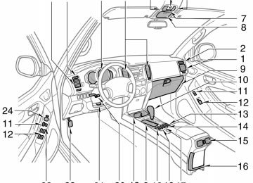
If the headlights or other electrical components do not work, check the fuses. If any of the fuses are blown, they must be replaced. See “Fuse locations” on page 356 in Sec- tion 7- 1 for locations of the fuses. Turn the ignition switch and inoperative component off. Pull the suspected fuse straight out and check it. Determine which fuse may be causing the problem. The lid of the fuse box shows the name of the circuit for each fuse. See page 397 in Section 8 for the functions controlled by each circuit.
Type A fuses can be pulled out by using the pull- out tool. The location of the pull- out tool is shown in the illustration. If you are not sure whether the fuse has blown, try replacing the suspected fuse with one that you know is good. If the fuse has blown, push a new fuse into the clip. Only install a fuse with the amperage rat- ing designated on the fuse box lid. If you do not have a spare fuse, in an emergency you can pull out the “PWR OUTLET” or “HEATER NO.2” fuse, which may be dispensable for normal driving, and use it if its amperage rating is the same. If you cannot use one of the same amper- age, use one that is lower, but as close to the rating as possible. If the amperage is fuse might blow out again but this does not indicate anything wrong. Be sure to get the correct fuse as soon as possible and return the substitute to its original clip. It is a good idea to purchase a set of spare fuses and keep them in your ve- hicle for emergencies.
that specified,
lower
than
the
2004 4RUNNER from Sep. ’04 Prod. (OM35847U)
’04 4Runner_U (L/O 0409)
Adding washer fluid
the new
If fuse immediately blows out, there is a problem with the electrical sys- tem. Have your Toyota dealer correct it as soon as possible.
CAUTION
Never use a fuse with a higher am- perage rating, or any other object, in place of a fuse. This may cause ex- tensive damage and possibly a fire.
You may use plain water as washer fluid. However, in cold areas where tempera- tures range below the freezing point, use washer fluid containing antifreeze. This product is available at your Toyota dealer and most auto parts stores. Follow the manufacturer’s directions for how much to mix with water.
NOTICE
Do not use engine antifreeze or any other substitute because it may dam- age your vehicle’s paint.
If any washer does not work, the wash- er tank may be empty. Check the wash- er fluid level on the level gauge. If the washer fluid level is below “LOW” or only slightly above the “LOW” level, add washer fluid. For vehicles sold in Canada— If any washer does not work or low windshield washer fluid level warning light comes on, the washer tank may be empty. Add washer fluid.
383
2004 4RUNNER from Sep. ’04 Prod. (OM35847U)
’04 4Runner_U (L/O 0409)
the
The inside of the lens of exterior lights such as headlights may temporarily fog up when the lens becomes wet in the rain or in a car wash. This is not a problem because the is caused by fogging temperature difference between the outside and the windshield fogs up in the rain. However, if there large drop of water on the inside of the lens, or if there is water pooled light, contact your Toyota dealer.
inside of
inside
lens,
is a
just
like
the
the
following
illustrations show how
Replacing light bulbs— The to gain access to the bulbs. When replacing a bulb, make sure the ignition switch and light switch are off. Use bulbs with the wattage ratings given in the table.
CAUTION
(cid:1) To prevent burning yourself, do not replace the light bulbs while they are hot.
(cid:1) Halogen bulbs have pressurized gas inside and require special handling. They can burst or shatter if scratched or dropped. Hold a bulb only by its plastic or metal case. Do not touch the glass part of a bulb with bare hands.
NOTICE
Only use a bulb of the listed type.
384
2004 4RUNNER from Sep. ’04 Prod. (OM35847U)
’04 4Runner_U (L/O 0409)
A: HB3 halogen bulbs B: HB4 halogen bulbs C: Wedge base bulbs (clear) D: Wedge base bulbs (amber) E: Double end bulbs
Light bulbs
Bulb No.
Headlights (high beam) Headlights (high and low beams) Front fog lights Parking and front side marker lights Front turn signal lights (without daytime running light system) Front turn signal lights (with daytime running light system) Rear turn signal lights Stop/tail and rear side marker lights Back- up lights License plate lights High mounted stoplight Interior light Personal lights Vanity lights Door courtesy lights Glove box light Luggage compartment light Running board lights
9005
9006
9006
168—
4157NAK
— — 921
168
921
— — — — — — —60
51
5121
27/8
21
21/5
16
16
3.8
1.2
3.8Type
385
2004 4RUNNER from Sep. ’04 Prod. (OM35847U)
’04 4Runner_U (L/O 0409)
—Headlights
Low beam (outside)
High beam (inside)
1. Turn the bulb base counterclockwise to the front of the vehicle as shown.
2. Unplug the connector while depress-
ing the lock release.
If the connector is tight, wiggle it.
3. Install a new bulb and connector into turn them clockwise to the front of the vehicle.
the mounting hole and
Aiming is not necessary after replacing the bulb. When aiming adjustment is nec- essary, contact your Toyota dealer.
386
2004 4RUNNER from Sep. ’04 Prod. (OM35847U)
’04 4Runner_U (L/O 0409)
—Front fog lights
1. Turn the bulb base counterclockwise to the front of the vehicle as shown.
2. Unplug the connector while depress-
ing the lock release.
If the connector is tight, wiggle it.
3. Install a new bulb and connector into turn them clockwise to the front of the vehicle.
the mounting hole and
387
2004 4RUNNER from Sep. ’04 Prod. (OM35847U)
’04 4Runner_U (L/O 0409)
—Parking and front side marker lights
—Front turn signal lights
—Rear turn signal, stop/tail, rear side marker and back- up lights
Use a flat- bladed screwdriver which wrapped with a cloth.
is
388
2004 4RUNNER from Sep. ’04 Prod. (OM35847U)
’04 4Runner_U (L/O 0409)
—License plate lights
—High mounted stoplight
Clips
a: Rear turn signal light b: Stop/tail and rear side marker light c: Back- up light
Use a Phillips- head screwdriver.
the clips by using a
Disconnect flat- bladed screwdriver which is wrapped with a cloth.
389
2004 4RUNNER from Sep. ’04 Prod. (OM35847U)
’04 4Runner_U (L/O 0409)
390
2004 4RUNNER from Sep. ’04 Prod. (OM35847U)
’04 4Runner_U (L/O 0409)
SECTION 1- 10
OPERATION OF INSTRUMENTS AND CONTROLS Other equipment Multi- information display Compass Rear view monitor system Power outlet Glove box Garage door opener Auxiliary boxes Rear console box Tissue box holder Coin holder Trash holder Front cup holders Rear cup holders and tray Rear cup holders Bottle holders Tie- down hooks Grocery bag hooks Cargo net hooks Luggage cover Double deck Roof luggage carrier Floor mat
. . . . . . . . . . . . . . . . . . . . . . . . . . . . . . . . . . . . . . . . . . . . . . . . . . . . . . . . . . . . . . . . . . . . . . . . . . . . . . . . . . . . . . . . . . . . . . . . . . . . . . . . . . . . . . . . . . . . . . . . . . . . . . . . . . . . . . . . . . . . . . . . . . . . . . . . . . . . . . . . . . . . . . . . . . . . . . . . . . . . . . . . . . . . . . . . . . . . . . . . . . . . . . . . . . . . . . . . . . . . . . . . . . . . . . . . . . . . . . . . . . . . . . . . . . . . . . . . . . . . . . . . . . . . . . . . . . . . . . . . . . . . . . . . . . . . . . . . . . . . . . . . . . . . . . . . . . . . . . . . . . . . . . . . . . . . . . . . . . . . . . . . . . . . . . . . . . . . . . . . . . . . . . . . . . . . . . . . . . . . . . . . . . . . . . . . . . . . . . . . . . . . . . . . . . . . . . . . . . . . . . . . . . . . . . . . . . . . . . . . . . . . . . . . . . . . . . . . . . . . . . . . . . . . . . . . . . . . . . . . . . . . . . . . . . . . . . . . . . . . . . . . . . . . . . . . . . . . . . . . . . . . . . . . . . . . . . . . . . . . . . . . . . . . . . . . . . . . . . . . . . . . . . . . . . . . . . . . . . . . . . . . . . . . . . . . . . . . . . . . . . . . . . . . . . . . . . . . . . . . . . . . . . . . . . . . . . . . . . . . . . . . . . . . . . . . . . . . . . . . . . . . . . . . . . . . . . . . . . . . . . . . . . . . . . . . . . . . . . . . . . . . . . . . . . . . . . . . . . . . . . . . . . . . . . . . . . . . . . . . . . . . . . . . . . . . . . . . . . . . . . . . . . . . . . . . . . . . . . . . . . . . . . . . . . . . . . . . . . . . . . . . . . . . . . . . . . . . . . . . . . . . . . . . . . . . . . . . . . . . . . . . . . . . . . . . . . . . . . . . . . . . . . . . . . . . . . . . . . . . . . . . . . . . . . . . . . . . . . . . . . . . . . . . . . . . . . . . . . . . . . . . . . . . . . . . . . . . . . . . . . . . . . . . . . . . . . . . . . . . . .
238
241
246
250
252
253
256
258
259
259
260
261
262
263
264
265
265
265
266
267
268
269237
2004 4RUNNER from Sep. ’04 Prod. (OM35847U)
’04 4Runner_U (L/O 0409)
Multi- information display—
1. “RESET” button 2. “MODE” button 3. Air conditioning system without “DUAL”
button—Cruise information display Air conditioning system with “DUAL” button—Outside temperature and cruise information display
4. Clock 5. Air conditioning system without “DUAL”
button only—Outside temperature display
6. “:00” button 7. “M” button 8. “H” button
238
2004 4RUNNER from Sep. ’04 Prod. (OM35847U)
’04 4Runner_U (L/O 0409)
—Clock
—Outside temperature display (air conditioning system without “DUAL” button)
the
ignition switch
the multi- information display
—Before using the multi- information display Operate with the ignition switch on. to When “ON”, the last previously used mode dis- played just before the ignition switch is turned off will appear. If the electrical power source has been disconnected the multi- information display, the display will automatically be set to the initial mode.
turned
from
is
CAUTION
Do not adjust the display while the vehicle is moving. Be sure to adjust the display only when the vehicle is stopped.
the
time
To reset the hour: Push the “H” button. To reset the minutes: Push the “M” button. If quick adjustment to a full hour is de- sired, push the “:00” button. if the “:00” button is de- For example, pressed when is between 1:01—1:29, the time will change to 1:00. If the time will change to 2:00. The key must be in the “ACC” or “ON” position. If the electrical power source has been disconnected from the clock, the time dis- play will automatically be set to 1:00 (one o’clock).
is between 1:30—1:59,
time
the
from
temperature
The displayed ranges - 30(cid:4)C (- 22(cid:4)F) up to 50(cid:4)C (122(cid:4)F). The key must be in the “ON” position. If there is some abnormality in the con- nection of the outside air temperature sen- sor, “- - (cid:4)C” (“- - (cid:4)F”) will appear on the display. If “- - (cid:4)C” (“- - (cid:4)F”) appears on the display, contact your Toyota dealer. There may be a case that “- - (cid:4)C” (“- - (cid:4)F”) appears momentarily when the ignition is quickly turned to “ON”. It is normal if it goes out soon.
239
2004 4RUNNER from Sep. ’04 Prod. (OM35847U)
’04 4Runner_U (L/O 0409)
—Cruise information display
Air conditioning system with “DUAL” button only—
temperature display
The outside (air conditioning system with “DUAL” but- ton) and cruise information display indi- cates the following information. Every time you push the “MODE” but- ton, the display toggles through this information. 1. Outside temperature 2. Driving range 3. Average fuel consumption 4. Average vehicle speed 5. Display off The displayed values in the cruise infor- mation display indicate general driving conditions. Accuracy varies with driving habits and road conditions.
1. Outside temperature (“OUTSIDE (cid:4)C”
or “OUTSIDE (cid:4)F”)
from
indi-
temperature
The outside temperature display cates the outside air temperature. The displayed value is updated every 1
second. The displayed ranges - 30(cid:4)C (- 22(cid:4)F) up to 50(cid:4)C (122(cid:4)F). If there is some abnormality in the con- nection of the outside air temperature sen- sor, “- - (cid:4)C” (“- - (cid:4)F”) will appear on the display. If “- - (cid:4)C” (“- - (cid:4)F”) appears on the display, contact your Toyota dealer. There may be a case that “- - (cid:4)C” (“- - (cid:4)F”) appears momentarily when the ignition is quickly turned to “ON”. It is normal if it goes out soon.240
2004 4RUNNER from Sep. ’04 Prod. (OM35847U)
’04 4Runner_U (L/O 0409)
2. Driving range
(“RANGE MI” or “RANGE km”)
3. Average fuel consumption
(“AVG. MPG” or “AVG. L/100 km”)
Compass
It
the
fuel
indicates
fuel gauge reaches “E”.
The distance the vehicle can travel with the remaining is calculated and displayed based on the quantity of re- maining fuel and past fuel consumption. The driving range display the approximate distance that you can drive until is different from the actual distance traveled. The displayed value is updated about ev- ery 10 seconds. Every time you refuel the vehicle, the cal- culation is reset. The actual driving range varies with driv- ing habits and road conditions. If fuel con- sumption is good, the driving range will be longer. If fuel consumption is poor, the driving range will be shorter. If the low fuel level warning light comes on, refuel even indicates that the vehicle can be driven further.
the display
if
total
Average fuel consumption is calculated and displayed based on total driving distance and fuel consumption with the engine running. The displayed value is updated about ev- ery 10 seconds. To the “RESET” button about 1 second. 4. Average vehicle speed
calculation,
reset
push
the
(“AVG. MPH” or “AVG. km/h”)
Average vehicle speed is calculated and displayed based on total driving dis- tance and total driving time with the engine running. The displayed value is updated about ev- ery 10 seconds. To the “RESET” button about 1 second.
calculation,
reset
push
the
The direction is indicated on the inside rear view mirror. If the ignition switch was turned off with the system on, the system will automati- cally turn back on when the ignition switch is turned on. Push the “COMP” switch to turn the com- pass system on and off.
241
2004 4RUNNER from Sep. ’04 Prod. (OM35847U)
indicates
the vehicle
the direction The compass that the above case, it shows that the vehicle is heading north.
is heading.
In
Displays
NE SE SW NW
Directions
North
Northeast
East
Southeast
South
Southwest
West
Northwest
The compass may not show the correct direction in the following conditions: (cid:2) The vehicle is stopped immediately af-
ter turning.
(cid:2) The compass does not adjust while the
vehicle is stopped.
(cid:2) The ignition switch is turned off imme-
diately after turning.
(cid:2) The vehicle is on an inclined surface.
242
’04 4Runner_U (L/O 0409)
(cid:2) The vehicle is in a place where the earth’s magnetic field is subject to in- terference by artificial magnetic fields (underground parking, under a steel tower, between buildings, roof parking, near a crossing, near a large vehicle, etc.).
(cid:2) The vehicle is magnetized. (There is a magnet or a metal object on or near the inside rear view mirror.)
the deviation
(cid:2) The battery has been disconnected. If your vehicle is out of the set zone, refer to “CALIBRATING THE COMPASS” below to set the zone number. If the compass works to calibrate the direction automati- cally while the vehicle is in motion. For additional precision or calibrating, see COMPASS” below.
for complete THE
“CALIBRATING
is small,
Compass sensor
The compass sensor is on the wind- shield.
NOTICE
Do not put magnets or a metal object on or near the inside rear view mirror of the vehicle. Doing this may cause malfunction of the compass sensor.
2004 4RUNNER from Sep. ’04 Prod. (OM35847U)
’04 4Runner_U (L/O 0409)
243
2004 4RUNNER from Sep. ’04 Prod. (OM35847U)
the
from
CALIBRATING THE COMPASS (deviation calibration) the compass The direction display on true direction deter- deviates mined by the earth’s magnetic field. The angle of deviation varies according to the geographic position of the vehicle. To adjust this deviation, stop the vehicle, then push and hold the “COMP” switch until the zone number appears on the dis- play. Then push the “COMP” switch, refer- ring to the following map to select the number of the zone where the vehicle is.
’04 4Runner_U (L/O 0409)
Samoa: 5
Guam:
Saipan: 8
After calibration, leaving the system for several seconds returns it to the compass mode.
CAUTION
Do not adjust the display while the vehicle is moving. Be sure to adjust the display only when the vehicle is stopped.
Zone number
244
2004 4RUNNER from Sep. ’04 Prod. (OM35847U)
’04 4Runner_U (L/O 0409)
the direction display on
CALIBRATING THE COMPASS (circling calibration) Sometimes the compass may not change after a turn. To rectify this, stop the vehicle and push and hold the “COMP” switch until “C” appears on the display. If “C” appears on the display because of a drastic change in the magnetic field, perform circling calibration.
in a circle, drive around
Drive the vehicle in a circle at 8 km/h (5
mph) or less. If there is not enough space to drive the block. After driving 1 to 3 circles in the above method, calibration is completed when the direction is shown on the display. If calibration cannot be performed because of the magnetized vehicle etc., take your vehicle to Toyota dealer.Perform circling calibration just after you have purchased your Toyota. And then always perform circling calibration after the battery has been removed, re- placed or disconnected. (cid:2) Do not perform circling calibration of the compass the earth’s magnetic field is subject to in- terference by artificial magnetic fields (underground parking, under a steel tower, between buildings, roof parking, near a crossing, near a large vehicle, etc.).
in a place where
(cid:2) During calibration, do not operate elec- tric systems (moon roof, power win- dows, etc.) as they may interfere with the calibration.
245
2004 4RUNNER from Sep. ’04 Prod. (OM35847U)
’04 4Runner_U (L/O 0409)
CAUTION
(cid:2) When doing the circling calibration, be sure to secure a wide space, and watch out for people and ve- hicles in the neighborhood. Do not violate any local traffic rules while performing circling calibration.
(cid:2) Do not adjust the display while the vehicle is moving. Be sure to adjust the display only when the vehicle is stopped.
Rear view monitor system The rear view monitor system assists the driver by displaying images of the rear of the vehicle during backing up. The displayed image on the screen is a horizontally reversed mirror image of the inside rear view mirror. To display the rear view on the screen, place the selector lever in the “R” posi- tion when the in the “ON” position. If you move the selector lever out of the “R” position, the previous screen. Operating another func- tion of the navigation system will display another screen. The rear view monitor system is an auxil- iary device intended to back up. When backing up, be sure to check behind and all around the vehicle visually.
the screen returns
ignition switch
to
CAUTION
(cid:2) Do not rely entirely on the rear
view monitor system. Use caution just as you would when backing up any vehicle.
246
image on
(cid:2) Never back up while looking only at the screen. The the screen may differ from actual con- ditions. If you back up while look- ing only at the screen, you may hit a vehicle or have an unexpected accident. When backing up, be sure to check behind and all around the vehicle visually and with mirrors before proceeding.
NOTICE
(cid:1) Do not use the system when the back door is not completely closed. (cid:1) If the back of the vehicle is hit, the position and mounting angle of the camera may slip. Be sure to have the camera’s position and mounting angle checked at your Toyota deal- er.
(cid:1) If the temperature changes rapidly, such as when hot water is poured on it in cold weather, the system may not operate normally.
2004 4RUNNER from Sep. ’04 Prod. (OM35847U)
(cid:1) If the camera lens becomes dirty, it cannot transmit a clear image. If water droplets, snow, or mud ad- here to the lens, rinse with water and wipe with a soft cloth. If the lens is extremely dirty, wash with a mild cleanser and rinse.
(cid:1) Use your own eyes to assure safety as the displayed image may become darker and moving images may be slightly distorted when the display is cold.
’04 4Runner_U (L/O 0409)
AREA DISPLAYED ON SCREEN Image is displayed approximately level on screen. (cid:2) The area detected by the camera is limited. The camera does not detect objects which are close to either corner of the bumper or under the bumper.
On screen
Corners of bumper
247
2004 4RUNNER from Sep. ’04 Prod. (OM35847U)
’04 4Runner_U (L/O 0409)
that appears on
The distance the screen between three- dimensional ob- jects (such as vehicles) and flat sur- faces (such as the road) and the actual distance differ as follows. In reality, A=B
(cid:2) The area displayed on the screen may vary according to vehicle status or road conditions.
On screen
248
2004 4RUNNER from Sep. ’04 Prod. (OM35847U)
’04 4Runner_U (L/O 0409)
When water droplets are adhering to the camera, or when humidity is high (for example, when it rains) When mud) is adhering to the camera When the sun or the beam of head- lights is shining directly into the cam- era lens
foreign matter
(for example,
(cid:2) If a bright light (for example, sunlight reflected off the vehicle body) is picked up by the camera, the smear effect* peculiar to the CCD camera may occur. * : Smear effect—A phenomenon that oc- curs when a bright light (for example, sun- is light reflected off picked up by trans- mitted by light source appears to have a vertical streak above and below it.
the camera; when
the vehicle body)
the camera,
the
249
2004 4RUNNER from Sep. ’04 Prod. (OM35847U)
THE REAR VIEW MONITOR SYSTEM CAMERA (cid:2) The rear view monitor system camera is located on the back door as shown in the illustration.
(cid:2) The rear view monitor system camera uses a special lens. The distance of the images that appear on the screen differs from the actual distance.
the
to see
images on
(cid:2) In the following cases, it may become the
difficult screen, but this is not a malfunction. In the dark (for example, at night) When the temperature near the lens is high or low
’04 4Runner_U (L/O 0409)
Power outlet (12 VDC)
NOTICE
(cid:1) To prevent the fuse from being blown, do not use the electricity over the total vehicle capacity of 12
VDC/120W.(cid:1) To prevent the battery from being discharged, do not use the power outlets longer than necessary when the engine is not running.
(cid:1) Close the power outlet lids when the power outlets are not in use. Inserting anything other than an ap- propriate plug that fits the outlet, or allowing any liquid to get into the outlet may cause electrical fail- ure or short circuits.
Luggage compartment
for
The power outlets are designed power supply for car accessories. In the rear console box—To use the power outlet, push the lid of the auxil- iary box to open. The key must be in the “ACC” or “ON” position for the power outlet to be used.
Rear console box
250
2004 4RUNNER from Sep. ’04 Prod. (OM35847U)
’04 4Runner_U (L/O 0409)
Power outlet (115 VAC)
This power outlet is designed for use as a power supply for electric ap- pliances in the vehicle. The key must be in the “ON” position for the power outlet to be used. The maximum capacity for this power out- let is 115 VAC/100W. If you attempt to use an appliance that requires more than 115 VAC or 100W, the protection circuit will activate and cut the power supply. The power supply will restart automatically when you use an appliance that operates within the 115 VAC/100W limits.
To use the power outlet, push the main switch on the instrument panel. An indicator light will illuminate to indicate that the power outlet is ready for use. Push the main switch once again to turn the power outlet off. When the power out- let is not in use, make sure that the main switch is turned off.
NOTICE
(cid:1) To prevent the battery from being discharged, do not use the power outlet longer than necessary when the engine is not running.
(cid:1) Close the power outlet lid when the power outlet is not in use. Inserting anything other than an appropriate plug that fits the outlet may cause electrical failure or short circuits.
The power outlet is not designed for the following electric appliances even though their power consumption is un- der 115 VAC/100W. These appliances may not operate properly.
251
2004 4RUNNER from Sep. ’04 Prod. (OM35847U)
’04 4Runner_U (L/O 0409)
Glove box
(cid:2) Appliances with high initial peak watt- age: cathode- ray tube type televisions, compressor- driven refrigerators, electric pumps, electric tools, etc.
(cid:2) Measuring devices which process pre- cise data: medical equipment, measur- ing instruments, etc.
(cid:2) Other appliances requiring an extremely stable power supply: microcomputer- controlled electric blankets, touch sen- sor lamps, etc.
Certain electrical appliances may cause radio noise.
To use the glove box, do this. To open: Pull the lever. With the instrument panel lights on, the glove box light will come on. To lock: Insert the master key and turn it clockwise.
CAUTION
To reduce the chance of in case of an accident or a sudden stop, always keep the glove box door closed while driving.
injury
252
2004 4RUNNER from Sep. ’04 Prod. (OM35847U)
’04 4Runner_U (L/O 0409)
Garage door opener
On some models, an auxiliary box is located inside the glove box. To increase the capacity of the glove box, raise the lower panel of the auxiliary box.
(cid:3)
The garage door opener ( Universal Transceiver) is manufactured under license from HomeLink(cid:3) and can be programmed to operate garage doors, gates, entry doors, door locks, home lighting systems, and security systems, etc.
transmitter prior
(a) Programming the HomeLink(cid:3) The HomeLink(cid:3) in your vehicle has 3
buttons and you can store one program for each button. To ensure correct programming into the HomeLink(cid:3), install a new battery in the hand- held to program- ming. The battery side of the hand- held trans- mitter must be pointed away the HomeLink(cid:3) during the programming pro- cess. For Canadian users, follow the procedure “Programming an entrance gate/pro- in gramming all devices the Canadian market”. 1. Decide which of 3 HomeLink(cid:3) buttonsfrom
in
you want to program.
2. Place your hand- held garage transmit- ter 25 to 75 mm (1 to 3 in.) away from the surface of the HomeLink(cid:3).
Keep the indicator light on the HomeLink(cid:3) in view while programming.
253
2004 4RUNNER from Sep. ’04 Prod. (OM35847U)
’04 4Runner_U (L/O 0409)
3. Simultaneously press and hold
the hand- held garage transmitter button along with the selected HomeLink(cid:3) but- ton.
4. When
the
indicator
the HomeLink(cid:3) changes from a slow to a rapid flash after 20 seconds, you can release both buttons.
light on
5. Test the operation of the HomeLink(cid:3) by pressing the newly programmed button. If programming a garage door opener, check to see if the garage door opens and closes.
(on
light
indicator
If the garage door does not operate, iden- tify if your garage transmitter is of the “Rolling Code” type. Press and hold the programmed HomeLink(cid:3) button. The ga- rage door has the rolling code feature if the HomeLink(cid:3)) the flashes rapidly and then remains lit after 2 seconds. If your garage transmitter is the “Rolling Code” type, proceed to the heading “Programming a rolling code sys- tem”. 6. Repeat steps 2 through 5 for each re- maining HomeLink(cid:3) button to program another device.
it
is
to
is necessary
Programming a rolling code system “Rolling Code” If your device follow equipped, steps 1 through 4 under the heading “Programming the HomeLink(cid:3)” before proceeding with the steps listed below. 1. Locate the “training” button on the ceil- ing mounted garage door opener motor. The exact the button may vary by brand of garage door opener. Refer the owner’s guide supplied by the garage door opener manufacturer for the location of this “training” button.
location and color of
to
2. Press the “training” button on the ceil- ing mounted garage door opener motor. Following this step, you have 30 seconds in which to initiate step 3 below. 3. Press and release the vehicle’s pro- grammed HomeLink(cid:3) button twice. The garage door may open. the door does open, the programming process is complete. If the door does not open, press and release the button a third time. This third press and release will complete the programming process by opening the garage door.
If
now
should
recognize
The ceiling mounted garage door opener motor the HomeLink(cid:3) unit and be able activate the garage door up/down. 4. Repeat steps 1 through 3 for each re- maining HomeLink(cid:3) button to program another rolling code system.
Programming an entrance gate/program- ming all devices in the Canadian market 1. Decide which of the 3 HomeLink(cid:3) but-
2. Place
your
tons you want to program. hand- held
gate/device transmitter 25 to 75 mm (1 to 3 in.) away the HomeLink(cid:3).
surface
from
the
of
Keep the indicator light on the HomeLink(cid:3) in view while programming. 3. Press
selected
hold
and
the
HomeLink(cid:3) button.
4. Continuously press and release (cycle) transmitter the hand- held gate/device button every two seconds until step 5
is complete. thethe HomeLink(cid:3) changes from a slow to a rapid flash after 20 seconds, you can release both buttons.
light on
5. When
indicator
254
2004 4RUNNER from Sep. ’04 Prod. (OM35847U)
’04 4Runner_U (L/O 0409)
(c) Erasing