- 2009 Nissan Altima Owners Manuals
- Nissan Altima Owners Manuals
- 2002 Nissan Altima Owners Manuals
- Nissan Altima Owners Manuals
- 1999 Nissan Altima Owners Manuals
- Nissan Altima Owners Manuals
- 2004 Nissan Altima Owners Manuals
- Nissan Altima Owners Manuals
- 2003 Nissan Altima Owners Manuals
- Nissan Altima Owners Manuals
- 1997 Nissan Altima Owners Manuals
- Nissan Altima Owners Manuals
- 2010 Nissan Altima Owners Manuals
- Nissan Altima Owners Manuals
- 1996 Nissan Altima Owners Manuals
- Nissan Altima Owners Manuals
- 2005 Nissan Altima Owners Manuals
- Nissan Altima Owners Manuals
- 1998 Nissan Altima Owners Manuals
- Nissan Altima Owners Manuals
- 2008 Nissan Altima Owners Manuals
- Nissan Altima Owners Manuals
- 2007 Nissan Altima Owners Manuals
- Nissan Altima Owners Manuals
- 2001 Nissan Altima Owners Manuals
- Nissan Altima Owners Manuals
- 2000 Nissan Altima Owners Manuals
- Nissan Altima Owners Manuals
- 2011 Nissan Altima Owners Manuals
- Nissan Altima Owners Manuals
- 2012 Nissan Altima Owners Manuals
- Nissan Altima Owners Manuals
- 2006 Nissan Altima Owners Manuals
- Nissan Altima Owners Manuals
- Download PDF Manual
-
tions for installation and use. Children Children who are too large for child re- straints should be seated and restrained by the seat belts which are provided. NISSAN recommends that children sit in the rear seat if possible. According to accident statistics, children are safer when properly restrained in the rear seat than in the front seat. If the child’s seating position has a shoulder belt that fits close to the face or neck, the use of a booster seat (commercially avail- able) may help overcome this. The booster seat should raise the child so that the shoul- der belt is properly positioned across the top, middle portion of the shoulder and the lap belt is low on the hips. The booster seat should fit the vehicle seat and have a label certifying that it complies with Federal Motor Vehicle Safety Standards or Canadian Mo- tor Vehicle Safety Standards. Once the
2-25
child has grown so the shoulder belt is no longer on or near the face and neck, use the shoulder belt without the booster seat.
WARNING
Never let a child stand or kneel on any seat and do not allow a child in the cargo areas while the vehicle is mov- ing. The child could be seriously in- jured or killed in an accident.
Pregnant women NISSAN recommends that pregnant women use seat belts. Contact your doctor for spe- cific recommendations. The lap belt should be worn snug and positioned as low as possible around the hips, not the waist. Injured persons NISSAN recommends that injured persons use seat belts. Check with your doctor for specific recommendations.
Z X
For most effective protection when the vehicle is in motion, the seat should be upright. Always sit well back in the seat and adjust the seat belt properly.
Fastening the belts 1. Adjust the seat.
APD0500
3-POINT TYPE WITH RETRACTOR
WARNING
c Every person who drives or rides in this vehicle should use a seat belt at all times.
c Do not ride in a moving vehicle when the seatback is reclined. This can be dangerous. The shoulder belt will not be against your body. In an accident you could be thrown into it and re- ceive neck or other serious injuries. You could also slide under the lap belt and receive serious internal injuries.
PD1023M
2. Slowly pull the seat belt out of the retrac- tor and insert the tongue into the buckle until it snaps.
The retractor is designed to lock during a sudden stop or on impact. A slow pulling motion permits the belt to move, and allows you some freedom of move- ment in the seat.
2-26
Z X
PD1024M
3. Position the lap belt portion low and
snug on the hips as shown.
4. Pull the shoulder belt portion toward the
retractor to take up extra slack.
The front passenger side seat belt and rear 3-point seat belts have a cinching mecha- nism for child seat installation. It is referred to as the automatic locking mode. When the cinching mechanism is activated the seat belt cannot be withdrawn further until the seat belt tongue is detached from the buckle and fully retracted. Once re- tracted, the seat belt is in the emergency
locking mode. Refer to ‘‘Child Restraints for Infants and Small Children’’ later in this section for more information. The automatic locking mode should be used only for child seat installation. Dur- ing normal seat belt use by a passenger, the locking mode should not be acti- vated. If it is activated it may cause uncomfortable seat belt tension. Unfastening the belts To unfasten the belt, press the button on the buckle. The seat belt automatically retracts.
Checking seat belt operation (3-point type with retractor) Seat belt retractors are designed to lock belt movement using two separate methods: 1) When the belt is pulled quickly from the
retractor.
2) When the vehicle slows down rapidly. To increase your confidence in the belts, check their operation as follows: c Grasp the shoulder belt and pull quickly forward. The retractor should lock and restrict further belt movement. the retractor does not
If lock during this check or if you have any questions about belt operation, see your NISSAN dealer.
2-27
Z X
WARNING
After adjustment, release the buttons and try to move the shoulder belt an- chor up and down to make sure it is securely fixed in position.
PD1321
Shoulder belt height adjustment (For front seats) The shoulder belt anchor height should be adjusted to the position best for you. (See ‘‘Precautions on Seat Belt Usage’’.) To ad- just, squeeze the release buttons and move the shoulder belt anchor to the desired position, so the belt passes over the center of the shoulder. The belt should be away from your face and neck, but not falling off of your shoulder.
APD0105
2-POINT TYPE WITHOUT RETRACTOR (center position of rear seat) Fastening the belts 1. Insert the tongue into the buckle until it snaps. Both the tongue and the buckle are marked CENTER.
2-28
Z X
ICM021
APD0106
APD0104
2. To lengthen, hold the tongue at a right angle to the belt and pull on the belt. To shorten, pull the end of the belt attached to the belt clip away from the tongue, then pull the belt clip to take up the slack.
3. Position the lap belt low and snug on
the hips as illustrated. Unfastening the belt To unfasten the belt, press the button on the buckle.
Selecting correct set of belts The center seat belt buckle and tongue are identified by the CENTER label. The center seat belt tongue can be fastened only into the center seat belt buckle.
2-29
Z X
is not possible to properly fit
SEAT BELT EXTENDERS If, because of body size or driving position, it the lap- shoulder belt and fasten it, an extender is available which is compatible with the in- stalled seat belts. The extender adds ap- proximately 8 inches (200 mm) of length and may be used for either the driver or front passenger seating position. See your NIS- SAN dealer for assistance if the extender is required.
WARNING
c Only NISSAN belt extenders, made by the same company which made the original equipment belts, should be used with NISSAN belts.
c Persons who can use the standard seat belt should not use an extender. Such unnecessary use could result in serious personal injury in the event of an accident.
SEAT BELT MAINTENANCE c To clean the seat belt webbings, apply a mild soap solution or any solution rec- ommended for cleaning upholstery or carpets. Then brush the webbing, wipe it with a cloth and allow it to dry in the shade. Do not allow the seat belts to retract until they are completely dry.
c If dirt builds up on the shoulder belt guide of the seat belt anchors, the seat belts may retract slowly. Wipe the shoul- der belt guide with a clean, dry cloth.
c Periodically check to see that the seat belt and the metal components, such as buckles, tongues, retractors, flexible wires and anchors, work properly. If loose parts, deterioration, cuts or other damage on the webbing is found, the entire seat belt assembly should be re- placed.
CHILD RESTRAINTS FOR INFANTS AND SMALL CHILDREN
WARNING
c Infants and small children should always be placed in an appropriate child restraint while riding in the ve- hicle. Failure to use a child restraint can result in serious injury or death. c Children and infants should never be carried on your lap. It is not possible for even the strongest adult to resist the forces of a severe accident. The child could be crushed between the adult and parts of the vehicle. Also, do not put the same seat belt around both your child and yourself.
c Nissan recommends that the child restraint be installed in the rear seat. According to accident statistics, children are safer when properly re- strained in the rear seat than in the front seat.
c An improperly installed child re- straint could lead to serious injury or death in an accident.
In general, child restraints are designed to be installed with a lap belt or the lap portion of a three point type seat belt.
2-30
Z X
Child restraints specially designed for infants and small children are offered by several manufacturers. When selecting any child re- straint, keep the following points in mind: 1) Choose only a restraint with a label cer- tifying that it complies with Federal Motor Vehicle Safety Standard 213 or Cana- dian Motor Vehicle Safety Standard 213. 2) Check the child restraint in your vehicle to be sure it is compatible with the vehi- cle’s seat and seat belt system. Choose a child restraint that meets the guidelines of the Society of Automotive Engineers recommended practice J1819 for child restraint installation.
3) If the child restraint is compatible with your vehicle, place your child in the child restraint and check the various adjust- ments to be sure the child restraint is compatible with your child. Always follow all recommended procedures.
All U.S. states and provinces of Canada require that infants and small children be restrained in approved child restraints at all times while the vehicle is being operated.
WARNING
c Never install a rear-facing child re- straint in the front seat. An inflating air bag could seriously injure or kill your child. A rear-facing child re- straint must only be used in the rear seat. See ‘‘Installation on front pas- senger seat’’ for details.
c Improper use of a child restraint can result in increased injuries for both the infant or child and other occu- pants in the vehicle.
c Follow all of the child restraint manu- facturer’s instructions for installa- tion and use. When purchasing a child restraint, be sure to select one which will fit your child and vehicle. It may not be possible to properly install some types of child restraints in your vehicle.
c If the child restraint is not anchored properly, the risk of a child being injured in a collision or a sudden stop greatly increases.
c Adjustable seatbacks should be po- sitioned to fit the child restraint, but as upright as possible.
2-31
c After attaching the child restraint, test it before you place the child in it. Tilt it from side to side. Try to tug it forward and check to see if the belt holds the restraint in place. If the restraint is not secure, tighten the belt as necessary, or put the restraint in another seat and test it again.
c For a front-facing child restraint, if the seat position where it is installed has a 3-point type lap/shoulder belt, check to make sure the shoulder belt does not go in front of the child’s face or neck. If it does, put the shoul- der belt behind the child restraint.
c When your child restraint is not in use, keep it secured with a seat belt to prevent it from being thrown around in case of a sudden stop or accident.
CAUTION
c Remember that a child restraint left in a closed vehicle can become very hot. Check the seating surface and buckles before placing your child in the child restraint.
Z X
APD0534
PD1174
PD1331
Installation on rear seat Center lap belt When you install a child restraint in a rear center seat, follow these steps: 1. Position the child restraint on the seat as illustrated. It can be placed in a forward facing or rear facing direction, depending on the size of the child. Always follow the restraint manufacturer’s instructions.
2. Route the seat belt tongue through the child restraint and insert it into the buckle until you hear and feel the latch engage. Be sure to follow the child restraint manu- facturer’s instructions for belt routing.
3. Remove all slack in the lap belt for a very tight fit by pulling forcefully on the lap belt adjustment.
4. Before placing the child in the child re- straint, use force to tilt the child restraint from side to side, and tug it forward to make sure it is securely held in place.
5. If it is not secure, try to tighten the belt again, or put the restraint in another seat. 6. Check to make sure the child restraint is
properly secured prior to each use.
Installation on rear outboard seating positions
WARNING
c The 3-point belt in your vehicle is equipped with a locking mode re- tractor which must be used when installing a child restraint.
c Failure to do so will result in the child restraint not being properly se- cured. It could tip over or otherwise be unsecured and cause injury to the child in a sudden stop or collision.
2-32
Z X
When you install a child restraint in a rear outboard seat, follow these steps: 1. Position the child restraint on the seat. It can be placed in a forward facing or rear facing direction, depending on the size of the child. Always follow the restraint manufacturer’s instructions.
2. Route the seat belt tongue through the child restraint and insert it into the buckle until you hear and feel the latch engage. Be sure to follow the child restraint manu- facturer’s instructions for belt routing.
3. Pull on the shoulder belt until all of the belt is fully extended and a click is heard. At this time, the belt retractor is in the automatic locking mode (child restraint mode). reverts back to emergency locking mode when the belt is fully re- tracted.
It
4. Allow the belt to retract. A clicking sound is heard as the belt retracts. This indi- cates that the retractor is in the automatic locking mode. Pull up on the belt to remove any slack in the belt.
After the child restraint is removed and the seat belt is allowed to wind back into the retractor, the automatic locking mode (child restraint mode) is canceled; the seat belt may be used as normal and only locks during a sudden stop or impact.
PD1332
5. Before placing the child in the child re- straint, use force to tilt the child restraint from side to side, and tug it forward to make sure it is securely held in place.
6. Check that the retractor is in the auto- matic locking mode by trying to pull more belt out of the retractor. If you cannot pull any more belt webbing out of the retrac- tor, the belt is in the automatic locking mode.
7. Check to make sure the child restraint is properly secured prior to each use. If the belt is not locked, repeat steps 3 through 6.
2-33
Z X
sions listed below must be used:
Bolt diameter: 8.0 mm Bolt length: more than 1.18 in (30 mm) Thread pitch: 1.25 mm
Secure the top strap to the attaching bolt which provides the straightest installation of the top strap.
WARNING
Child restraint anchor points are de- signed to withstand only those loads imposed by correctly fitted child re- straints. Under no circumstances are they to be used for adult seat belts or harnesses.
APD0107
TOP STRAP CHILD RESTRAINT If your child restraint has a top strap, it must be secured to the provided anchor point. Anchor bracket hardware must be installed. The top strap anchor bracket hardware is available through your NISSAN dealer. U.S. Part #88894-89900
Canadian Part #88894-89902
Secure the child restraint with the center lap belt or the lap portion of an outboard 3-point belt and latch the top strap hook onto the appropriate anchor bracket. To install the anchor bracket, a metric bolt of the dimen-APD0108
Anchor point locations Anchor points are located under the rear parcel shelf finisher. To use attaching hardware for child re- straints with top straps, follow these instruc- tions carefully: 1. Open the trunk and find the anchor point nuts on the underside of the rear parcel shelf. Thread a bolt (8.0 mm diameter, 1.25 pitch) up through the nut behind the seating position where the child restraint will be installed and use it to break through the rear parcel shelf support
2-34
Z X
material. There are pre-cut circles at each anchor point location that should break away from the shelf support mate- rial when pressure is applied to them. Remove the bolt after you feel the pre-cut circle separate from the shelf support material.
2. Cut a small slit through the parcel shelf fabric at the anchor point location. Reach through the fabric with a tool such as a pair of needle-nose pliers and remove the pre-cut circle in the parcel shelf sup- port material.
3. Install the bolt through the top strap hook
and into the anchor point nut.
4. Be sure to follow all of the instructions that accompany the top strap attaching hardware.
APD0647
Installation on front passenger seat
WARNING
c Never install a rear-facing child re- straint in the front passenger seat. Supplemental air bags inflate with great force. A rear-facing child re- straint could be struck by the supple- mental air bag in a crash and could seriously injure or kill your child.
c If you install a forward-facing child restraint in the front passenger seat, place the passenger seat as far back as possible.
A child restraint with a top strap should not be used in the front passenger seat.
WARNING
c The 3-point belt in your vehicle is equipped with a locking mode re- tractor which must be used when installing a child restraint.
c Failure to use the retractor’s locking mode will result in the child restraint not being properly secured. The seat could tip over or otherwise be unse- cured and cause injury to the child in a sudden stop or collision.
2-35
Z X
When you install a child restraint in the front seat, follow these steps: 1. Position the child restraint on the front passenger seat. It should be placed in a forward-facing direction only. Move the seat as far back from the instrument panel as possible. Always follow the child restraint manufacturer’s instructions. Child restraints for infants must be used in the rear-facing direction and therefore must not be used in the front seat.
2. Route the seat belt tongue through the child restraint and insert it into the buckle until you hear and feel the latch engage.
PD1336
Be sure to follow the child restraint manu- facturer’s instructions for belt routing. 3. Pull on the shoulder belt until all of the belt is fully extended and a click is heard. At this time, the belt retractor is in the automatic locking mode (child restraint mode). reverts back to emergency locking mode when the belt is fully re- tracted.
It
4. Allow the belt to retract. A clicking sound is heard as the belt retracts. This indi- cates that the retractor is in the automatic locking mode. Pull up on the belt to remove any slack in the belt.
2-36
5. Before placing the child in the child re- straint, use force to tilt the child restraint from side to side, and tug it forward to make sure it is securely held in place.
6. Check that the retractor is in the auto- matic locking mode by trying to pull more belt out of the retractor. If you cannot pull any more belt webbing out of the retrac- tor, the belt is in the automatic locking mode.
7. Check to make sure the child restraint is properly secured prior to each use. If the lap belt locked, repeat steps 3
through 6.is not
After the child restraint is removed and the seat belt is allowed to wind back into the retractor, the automatic locking mode (child restraint mode) is canceled; the seat belt may be used as normal and only locks during a sudden stop or impact.
Z X
TILTING STEERING WHEEL
OUTSIDE MIRROR REMOTE CONTROL
OUTSIDE MIRRORS
PD1028
APD0529
AIC0504
The driver and passenger outside mirrors are foldable. Push the outside mirror back- ward to fold it.
Tilt operation Push the lock lever down and adjust the steering wheel up or down to the desired position. Pull steering wheel in place.
the lock lever up firmly to lock the
WARNING
Do not adjust the steering wheel while driving. You could lose control of your vehicle and cause an accident.
The outside mirror remote control only op- erates when the ignition switch is in the ACC or ON position. Push the right or left side of the switch to select the right or left outside mirror, then adjust using the control lever. WARNING
Objects viewed in the outside mirror on the passenger side are closer than they appear. Be careful when moving to the right. Using only this mirror could cause an accident. Use the inside mirror or glance over your shoulder to properly judge distances to other objects.
2-37
Z X
INSIDE MIRROR
VANITY MIRROR
PD1006M
APD0510
The night position reduces glare from the headlights of vehicles behind you at night.
WARNING
Use the night position only when nec- essary, because it reduces rear view clarity.
To access the vanity mirror, pull the sun visor down and flip open the mirror cover. Some vanity mirrors are illuminated and turn on when the mirror cover is opened.
2-38
Z X
Z X
3 Heater, air conditioner and audio system
Ventilators ..............................................................3-2
Heater and air conditioner (manual) ......................3-2
Controls ..................................................................3-3
Heater operation ....................................................3-3
Air conditioner operation (if so equipped)..............3-4
Air flow charts.........................................................3-5
Heater and air conditioner (automatic) (if so equipped) ...............................................................3-8
Radio ....................................................................3-11
Clock-radio (if so equipped).................................3-11AM-FM radio with cassette player .......................3-12
Radio operation....................................................3-12
Cassette tape operation.......................................3-14
AM-FM radio with cassette player and compact disc player .............................................3-17
Radio operation....................................................3-17
Cassette tape operation.......................................3-19
Compact disc (CD) player operation....................3-21
Antenna ................................................................3-22
CB radio or car phone..........................................3-23Z X
VENTILATORS
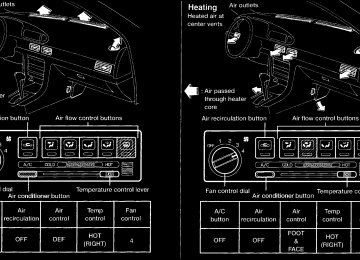
HEATER AND AIR CONDITIONER (MANUAL)
Open or close (side vents only), and adjust the air flow direction of ventilators.
HA1073
WARNING
c The air conditioner cooling function operates only when the engine is running.
3-2
AHA0527
c Do not
leave children, unreliable adults, or pets alone in your vehicle. On hot sunny days, temperatures in a closed vehicle could quickly become high enough to cause severe or possi- bly fatal injuries to people or animals.
Z X
c Do not use the recirculation mode for long periods as it may cause the inte- rior air to become stale and the win- dows to fog up.
c Positioning of the heating or air con- ditioning controls should not be done while driving, in order that full attention may be given to the driving operation.
turns the fan on and off, and
CONTROLS Fan control dial This dial controls fan speed. Air flow control buttons These buttons allow you to select the air flow outlets.
— Air flows from center and side
ventilators.
— Air flows from center and side
ventilators and foot outlets.
— Air flows mainly from foot outlets. — Air flows from defroster outlets
and foot outlets.
— Air flows mainly from defroster
outlets.
Temperature control lever This lever allows you to adjust the tempera- ture of the outlet air. Air recirculation button Off position: Outside air is drawn into the passenger compartment and distributed through the selected outlet. Use the off position for normal heater or air conditioner operation. On position (Indicator light on): Interior air is recirculated inside the vehicle. Push the air recirculation button to the ON position when driving on a dusty road, to avoid traffic fumes, and for maximum cool- ing when using the air conditioner. Air conditioner button (If so equipped) This button is provided only on vehicles equipped with an air conditioner. Start the engine, move the fan control dial to
3-3
the desired (1 to 4) position and push the A/C button to turn on the air conditioner. The indicator light comes on when the air conditioner is on. To stop the air condi- tioner, push the switch again. The air conditioner cooling function op- erates only when the engine is running. HEATER OPERATION Heating This mode is used to direct heated air from the foot outlets. Some air also flows from the defroster outlets. 1. Push the air recirculation button to the off
position for normal heating.
2. Push the 3. Move the fan control dial to the desired
button in.
position.
4. Move the temperature control lever to the desired position between the middle and the HOT position.
Ventilation This mode directs outside air to the side and center ventilators.
Z X
1. Push the air recirculation button to the off
position. 2. Push the 3. Move the fan control dial to the desired
button in.
position.
4. Move the temperature control lever to the
desired position.
Defrosting or defogging This mode is used to defrost/defog the windows. 1. Push the 2. Move the fan control dial to the desired
button in.
position.
3. Move the temperature control lever to the desired position between the middle and the HOT position.
c To quickly remove ice or fog from the windows, turn on the fan control dial to 4
and the temperature control lever to the full HOT position.c When the
switch is pushed, the air conditioner automatically turns on to de- fog the windshield, and the air recircula- tion mode automatically turns off.
Outside air is drawn into the passenger compartment to improve the defogging performance.
Bi-level heating/cooling This mode directs air from the side, center and foot outlets. 1. Push the air recirculation button to the off
position. 2. Push the 3. Move the fan control dial to the desired
button in.
position.
4. Move the temperature control lever to the
desired position.
Heating and defogging This mode heats the interior and defogs the windshield. 1. Push the 2. Move the fan control dial to the desired
button in.
position.
3. Move the temperature control lever to the desired position between the middle and the HOT position.
3-4
Operating tips c Clear snow and ice from the wiper blades and air inlet in front of the windshield. This improves heater op- eration.
c When the
or
switch is se- lected, the air recirculation mode auto- matically turns off. Outside air is drawn into the passenger compartment to improve the defogging performance.
AIR CONDITIONER OPERATION (If so equipped) Start the engine, move the fan control dial to the desired (1 to 4) position and push in the A/C button to activate the air conditioner. When the air conditioner is on, cooling and dehumidifying functions are added to the heater operation. The air conditioner cooling function op- erates only when the engine is running.
Z X
Cooling This mode is used to cool and dehumidify. 1. Push the air recirculation button to the off
position. 2. Push the 3. Move the fan control dial to the desired
button in.
position.
4. Push on the air conditioner button. The
indicator light comes on.
5. Move the temperature control lever to the
desired position.
c For quick cooling when the outside tem- perature is high, push the air recirculation button to the on position. Be sure to return the air recirculation button to the off position for normal cooling.
Dehumidified heating This mode is used to heat and dehumidify. 1. Push the air recirculation button to the off
position. 2. Push the 3. Move the fan control dial to the desired
button in.
position.
4. Push on the air conditioner button. The
indicator light comes on.
5. Move the temperature control lever to the
desired position.
Dehumidified defogging This mode defogs the windows and dehu- midifies. 1. Push the 2. Move the fan control dial to the desired
button in.
position.
3. Push the air conditioner button. The indi-
cator light comes on.
4. Move the temperature control lever to the
desired position. When the button is pushed, the air conditioner automatically turns on to de- fog the windshield, and the air recircula- tion mode automatically turns off.
Outside air is drawn into the passenger compartment to improve the defogging per- formance. Operating tips c Keep the windows and sun roof closed while the air conditioner is in operation.
3-5
c After parking in the sun, drive for two or three minutes with the windows open to vent hot air from the passenger compart- ment. Then, close the windows. This allows the air conditioner to cool the interior more quickly.
c The air conditioner system should be operated for about ten minutes at least once a month. This helps pre- vent damage to the system due to lack of lubrication. the coolant
temperature gauge ex- ceeds the H (hot) position, turn the air conditioner off. See ‘‘If your vehicle over- heats’’ in the ‘‘In case of emergency’’ section for additional information.
c If
AIR FLOW CHARTS The charts on the following pages show the switch and lever positions for MAXIMUM and QUICK heating, cooling, or defrosting.
Z X
3-6
AHA0528
Z X
3-7
AHA0529
Z X
HEATER AND AIR CONDITIONER (AUTOMATIC) (If so equipped)
WARNING
c The air conditioner cooling function operates only when the engine is running. c Do not
leave children, unreliable adults, or pets alone in your vehicle. On hot sunny days, temperatures in a closed vehicle could quickly be- come high enough to cause severe or possibly fatal injuries to people or animals.
AHA0534
c Do not use the recirculation mode for long periods as it may cause the interior air to become stale and the windows to fog up.
c Positioning of the heating or air con- ditioning controls should not be done while driving, in order that full attention may be given to the driving operation.
Controls Start the engine and operate the controls to activate the climate control system. Push the OFF switch to turn the system off.
3-8
The air conditioner cooling function op- erates only when the engine is running. Cooling and/or dehumidified heat- ing (AUTO mode) This mode may be used throughout the year as the system automatically works to main- tain the customer-selected temperature. Air flow distribution and fan speed are also controlled automatically. 1. Push the AUTO switch on. AUTO and the previously selected temperature appear in the display.
2. Push the temperature set button to set the desired temperature.
or
c Adjust
the temperature to about 75°F
(24°C) for normal operation.
c The temperature of the passenger com- partment is maintained automatically. Air flow distribution and fan speed are also controlled automatically. Heating (ECON mode) The ECON (economy) mode provides cli- mate control without activating the air con- ditioner. When only heating of the passen- ger compartment is desired, use this mode.
Z X
1. Push the ECON switch on. ECON ap-
pears in the display.
2. Push the temperature set button to set the desired temperature.
or
c The temperature of the passenger com- partment is maintained as selected by the temperature set button. Air flow dis- tribution and fan speed are also con- trolled automatically in an effort to reach the desired termperature.
c Do not select a temperature setting lower than the outside air temperature. Due to the absence of air conditioner operation, the selected interior temperature may not be reached.
c ECON mode is not recommended if the windows are fogging up. If the windows begin to fog up while using the ECON mode, use the procedures outlined in ‘‘Dehumidified defogging’’. Dehumidified defogging 1. Push the
switch on. The indicator
light comes on.
2. Push the temperature set button
to set the desired temperature.
or
c To quickly remove ice or fog from the outside of the windows, push the manual fan control switch and set to the maxi- mum position
c As soon as possible after the windshield is clean, push the AUTO switch to return to the auto mode.
c When the
switch is pushed, the air conditioner automatically turns on at out- side temperatures above 35°F (2°C) to defog the windshield, and the air recircu- lation mode automatically turns off. Outside air is drawn into the passenger compartment to improve the defogging performance.
Manual fan speed control Push the fan control switches to manually control the fan speed. Each fan speed is indicated by the shading of a fan blade on indicates the display. For example, that the fan is operating at low speed and indicates that the fan is operating at
medium-high speed. c Push the AUTO switch to return to auto-
matic control of the fan speed.
3-9
Air recirculation switch Push the air recirculation switch to recircu- late interior air inside the vehicle. The indi- cator light comes on. Push it again to draw outside air into the passenger compartment. The indicator goes out. c The air recirculation mode cannot be mode has
activated when the been selected.
Manual air flow control Pushing the manual air flow control switch selects the air outlet.
— Air flows from center and side
ventilators.
— Air flows from center and side
ventilators and foot outlets.
— Air flows mainly from foot outlets. — Air flows from defroster outlets
and foot outlets.
— Air flows mainly from defroster
outlets.
Z X
Operating tips c When the engine coolant
temperature and outside air temperature are low, the air flow from the foot outlets may not operate for a maximum of 180 seconds. This is not a malfunction. After the cool- ant temperature warms up, the air flows from the foot outlets normally.
Servicing air conditioner The air conditioner system in your NISSAN vehicle is charged with a refrigerant de- signed with the environment in mind. This refrigerant does not harm the earth’s ozone layer. Special charging equipment and lubricant is required when servicing your NISSAN air conditioner. Using improper refrigerants or lubricants will cause severe damage to your air conditioner system. See ‘‘Air conditioner system refrigerant and lubricant recommen- dations’’ in the ‘‘Technical and consumer information’’ section of this manual. Your NISSAN dealer is able to service your environmentally conscious air conditioner system.
AHA0501
The sensor on the instrument panel helps maintain a constant temperature; do not put anything on or around this sensor.
3-10
Z X
RADIO
influences.
To turn the radio on, turn the ignition key to ACC or ON. If you listen to the radio with the engine not running, turn the key to the ACC position. Radio reception is affected by station signal strength, distance from radio transmitter, buildings, bridges, mountains and other ex- ternal Intermittent changes in reception quality normally are caused by these external influences. CLOCK-RADIO (If so equipped) On vehicles equipped with an AM-FM radio and cassette player, a clock is integrated into the audio system. For further details, refer to ‘‘Clock Operation’’ later in this sec- tion.
3-11
Z X
AM-FM RADIO WITH CASSETTE PLAYER RADIO OPERATION Push the ON-OFF/VOL knob to turn the radio on. Push the ON-OFF/VOL knob once more to turn the radio off. Turn the knob to adjust the volume. Inserting a cassette tape into the cassette player while the radio is on turns the radio off and turns the cassette player on. Pushing the ON-OFF/VOL knob while a cassette tape is playing turns the cassette player off. Clock Operation Pressing the CLOCK button alternates the clock and the radio/cassette tape options in the display. Clock Set Depressing the CLOCK and the together CLOCK and utes.
buttons hours. Depressing the buttons together sets min-
sets
AHA0626
3-12
Z X
Clock Priority Mode In this mode the clock is shown in the display. If any radio or cassette tape func- tions are activated, the radio (or cassette tape) display illuminates for ten seconds then returns to the clock mode. NOTE: After clock adjustment, the radio is in the clock priority mode. Radio/Cassette Tape Priority Mode In this mode, the radio station illuminates in the display during radio operation. During cassette tape operation, TAPE illuminates in the display. Selecting the desired band Push the band select button (FM/AM) to change from AM to FM reception. The stereo indicator glows during FM stereo reception. When the stereo broadcast signal is weak, the radio automatically changes from stereo to monaural reception.
Tuning
WARNING
The radio should not be tuned while driving in order that full attention may be given to the driving operation.
Manual tuning Push down either manual
or
tuning button
SEEK tuning Push the SEEK/SCAN tuning button for less than 1.5 seconds. SEEK tuning begins from low to high frequencies and stops at the next broadcasting station. Pushing the but- ton again continues the SEEK function. Once the highest broadcasting station is reached, the radio continues in the SEEK mode at the lowest broadcast station. SCAN tuning Push the SEEK/SCAN tuning button for more than 1.5 seconds. SCAN illuminates in the display window. SCAN tuning begins from low to high frequencies and stops at each broadcasting station for five seconds. Push- ing the button again during this five second period stops SCAN tuning and the radio remains tuned to that station.
3-13
AHA0525
Station memory operations Six stations can be set for each band. 1. Tune to the desired station. 2. Push the desired select button for more
Z X
in the than 2 seconds. For example, diagram ch2 is to be memorized. The radio mutes when the select button is pushed.
3. The indicator, ch2, then comes on in the display and the sound resumes. Memo- rizing is now complete.
4. Other select buttons can be set in the
same manner.
If the battery cable is disconnected, or if the fuse opens, the radio memory is cancelled. In that case, reset the desired stations.
Adjusting tone quality and speaker balance To adjust BASS, TREB (treble), FADER, and BAL (balance) the control knobs must be released from their stowed positions. Pushing the knobs once moves them to the released position. In the released position, the knobs control tone quality. Turn the control knobs to adjust BASS and TREB to the most pleasing level. From the released position, the knobs must be pulled out in order to control FADER and BAL. FADER adjusts the sound level be-
3-14
AHA0522
tween the front and rear speakers, and BAL adjusts the sound level between the right and left speakers. Once sound quality is set to the desired levels, return the control knobs to the stowed position by pushing them in com- pletely and releasing. CASSETTE TAPE OPERATION Turn the ignition key to ACC or ON, then carefully insert a cassette tape into the tape door. The cassette tape automatically pulls into the player. The word TAPE and an arrow
Z X
indicating tape side illuminates in the dis- play window.
CAUTION
Do not force the cassette tape into the tape door. This could cause player damage.
The cassette tape automatically changes directions to play the other side when the first side is complete. At this time, the arrow in the display window changes direction. c To maintain good quality sound, NIS- SAN recommends using cassette tapes of 60 minutes or shorter in length.
c Cassette tapes should be removed from the player when not in use. Store cassettes in their protective cases and away from direct sunlight, heat, moisture and magnetic sources.
c Direct sunlight can cause the cassette to become deformed. The use of de- formed cassettes may cause the cas- sette to jam in the player.
c Do not use cassettes with labels which are peeling and loose. If used,
the label could jam in the player.
c If a cassette has loose tape, insert a pencil through one of the cassette hubs and rewind the tape firmly around the hubs. Loose tape may cause tape jamming and wavering sound quality.
c Over a period of time, the playback head, capstan and pinch roller may collect a tape coating residue as the tape passes over the head. This resi- due accumulation can cause weak or wavering sound, and should be re- moved periodically with a head clean- ing tape. If the residue is not removed periodically, the player may need to be disassembled for cleaning.
forwarding or rewinding the
Fast tape Push either the FF (fast forward) or REW (rewind) button for the desired direction. The display. To stop the FF or REW function, press the PLAY/STOP button.
symbol illuminates in the
or
Automatic Program Search (APS) fast forwarding or APS rewinding the tape Push either the APS FF or APS REW button while the cassette tape is playing. The tape runs quickly, stops, then plays the next selection. The indicator light flashes on and off while searching for the selection. The symbol illuminates in the
or
display. This system searches at the blank intervals between selections. If there is a blank inter- val within one selection or there is no inter- val between selections, the system may not stop in the desired or expected location. Changing the direction of tape play Push the PROG (program) select button. symbol illuminates in the The display to indicate side of program play. Playing and stopping the cassette tape Push the PLAY/STOP button while the cas- sette tape is playing to stop the tape. Push the button again to play the tape.
or
3-15
Z X
Dolby NR (noise reduction) Push the DOLBY NR button for Dolby NR encoded tapes to reduce high frequency tape noise. The indicator light comes on. Dolby NR is manufactured under license from Dolby Laboratories Licensing Corpora- tion. DOLBY NR and the double-D symbol are trademarks of Dolby Laboratories Li- censing Corporation. If
in the clock priority mode when the and TAPE illuminate in the display window for about ten seconds. The clock mode then returns to the display window. Metal or chrome tape usage The cassette player is automatically set to high performance play when playing a metal or chrome cassette tape. Ejecting the cassette tape Push the EJECT button. The cassette tape automatically comes out.
button is pressed,
3-16
Z X
AM-FM RADIO WITH CASSETTE PLAYER AND COMPACT DISC PLAYER RADIO OPERATION This radio has an FM Diversity reception system, which employs two antennas. One is a rod type antenna; the other is an antenna printed on the rear window. This system automatically switches to the an- tenna which is receiving the strongest radio signal. Power button Turn the ignition key to ACC or ON, then push the POWER button. The mode (radio, tape or CD) which was playing immediately before the system was turned off resumes playing. When no CD or tape is loaded, the radio comes on. Pushing the POWER button again turns the system off. VOL (volume) control knob Turn the VOL control knob to adjust the volume.
AHA0532
3-17
Z X
Adjusting tone quality and speaker balance To adjust BASS, TREB (treble), FADER, and BAL (balance) the control knobs must be released from their stowed positions. Pushing the knobs once moves them to the released position. In the released position, the knobs control tone quality. Turn the control knobs to adjust BASS and TREB to the most pleasing level. From the released position, the knobs must be pulled out in order to control FADER and BAL. FADER adjusts the sound level be-
AHA0526
tween the front and rear speakers, and BAL adjusts the sound level between the right and left speakers. Once sound quality is set to the desired levels, return the control knobs to the stowed position by pushing them in com- pletely and releasing. FM/AM band select button Pushing the FM/AM band select button changes the band. When the POWER button is pushed while the ignition switch is in the ACC or ON position, the radio comes on at the band
3-18
and the station last played. The FM stereo indicator, ST, glows during FM stereo reception. When the stereo broadcast signal is weak, the radio auto- matically changes from stereo to monaural reception. TUNE/DISC button
WARNING
The radio should not be tuned while driving in order that full attention may be given to the driving operation.
Use these buttons for manual tuning. To move quickly through the channels, hold either of the tuning buttons down for more than 1.5 seconds. SEEK/SCAN buttons SEEK tuning Push the SEEK/SCAN tuning button
or for less than 1.5 seconds. SEEK tuning begins from low to high frequencies or high to low frequencies, depending on which button is pressed, and stops at the next broadcasting station. Once the highest broadcasting station is reached, the radio
Z X
If
using
station.
continues in the SEEK mode at the lowest the broadcasting button, once the lowest broadcasting station is reached, the radio continues in the SEEK mode at the highest broadcasting station. Pushing the button again continues the SEEK function. SCAN tuning Push the SEEK/SCAN tuning button
or for more than 1.5 seconds. SCAN tun- ing begins from low to high frequencies or high to low frequencies, depending on which button is pressed. SCAN tuning stops at each broadcasting station for five sec- onds. Pushing the button again during this five second period stops SCAN tuning and the radio remains tuned to that station.
in the than 3 seconds. For example, diagram ch2 is to be memorized. The radio mutes when the select button is pushed.)
3. The indicator, ch2, then illuminates in the display and the sound resumes. Memo- rizing is now complete.
4. Other buttons can be set in the same
manner.
If the battery cable is disconnected, or if the radio fuse opens, the radio memory is can- celled. In that case, reset the desired stations. CASSETTE TAPE OPERATION Turn the ignition key to ACC or ON, and lightly insert the cassette tape into the tape door. The cassette tape automatically pulls into the player. The radio or CD turns off (if it is on) and the cassette tape begins to play.
CAUTION
Do not force the cassette tape into the tape door. This could cause player damage.
Z X
AHA0531
Station memory operations Six stations can be set for each band. 1. Tune to the desired station. 2. Push the desired select button for more
3-19
If the system is turned off by pushing the POWER button with the cassette tape still in the player, the tape resumes playing when the POWER button is pushed once again. TAPE button When this button is pushed with the system turned off and a tape loaded, the system comes on and the tape plays. When this button is pushed with either the radio or compact disc turned on and the tape loaded, the compact disc or the radio automatically turns off and the tape plays. While the tape is playing, pushing the TAPE button stops tape play. Pushing the button again resumes tape play. FF (fast forward) and REW (rewind) buttons Push the FF (fast forward) button to fast forward the tape. Push the REW (rewind) button to rewind the tape. Either the indicator light comes on when the FF or REW function is started. To stop the FF or REW function, press the TAPE button.
or
Automatic Program Search (APS) FF and APS REW buttons
When the APS FF button is pushed while the tape is being played, the next selection starts to play from the beginning. Push the APS FF button several times to skip several selections. The tape advances the number of selections the button is pushed (up to 9
selections). When the APS REW button is pushed, the selection being played starts over from the beginning. Push several times to fast rewind several selections. The tape rewinds the number of selections the button is pushed. Either light comes on when the APS FF or APS REW function is started. This system searches for the blank intervals between selections. If there is a blank inter- val within one selection or there is no inter- val between selections, the system may not stop in the desired or expected location. PROG (program) button Push the PROG (program) button to change the tape side while the tape is being played.indicator
the
or
The cassette tape automatically changes directions to play the other side when the first side is complete. Dolby NR (noise reduction) button Push the DOLBY NR button for Dolby NR encoded tapes to reduce high frequency tape noise. The indicator light comes on. Dolby NR is manufactured under license from Dolby Laboratories Licensing Corpora- tion. DOLBY NR and the double-D symbol are trademarks of Dolby Laboratories Li- censing Corporation. TAPE EJECT button Push this button to eject an inserted tape. When the tape ejects while playing, the system turns off. Precautions on cassette player op- eration c To maintain good quality sound, NISSAN recommends using cassette tapes of 60 minutes or shorter in length.
3-20
Z X
c Cassette tapes should be removed from the player when not in use. Store cassettes in their protective cases and away from direct sunlight, heat, moisture or magnetic sources.
c Direct sunlight can cause the cassette to become deformed. The use of de- formed cassettes may cause the cas- sette to jam in the player.
c Do not use cassettes that have peel- ing or loose labels. If used, the label could jam in the player.
c If a cassette has loose tape, insert a pencil through one of the cassette hubs and rewind the tape firmly. Loose tape may cause jamming and wavering sound quality.
c Over a period of time, the playback head, capstan and pinch roller may gather a tape coating residue as the tape passes over the head. This resi- due accumulation can cause a weak or wavering sound and should be re- moved periodically with a head clean- ing tape. If the residue is not removed periodically, the player may need to be disassembled for cleaning.
COMPACT DISC (CD) PLAYER OPERATION Turn the ignition key to the ACC or ON position and insert the compact disc into the slot with the label side facing up. The com- pact disc is automatically pulled into the slot and starts to play. If the radio or cassette tape is already operating, it automatically turns off and the compact disc begins to play.
CAUTION
Do not force the compact disc into the slot. This could damage the player.
If the system is turned off while the compact disc is playing, pushing the POWER button starts the compact disc. CD button When this button is pushed with the system off and the compact disc loaded, the system turns on and the compact disc starts to play. When this button is pushed with the com- pact disc loaded and the tape or the radio playing, radio automatically turns off and the compact disc starts to play.
the tape or
3-21
When this button is pushed while the com- pact disc is playing, the compact disc stops playing. FF (fast forward), REW (rewind) button When the FF (fast forward) or REW (rewind) button is pushed while the compact disc is playing, the compact disc plays at an in- creased speed while fast forwarding or re- winding. When the button is released, the compact disc returns to normal play speed. Automatic Program Search (APS) FF, APS REW button
When the APS FF button is pushed while the compact disc is playing, the selection following the present one starts to play from its beginning. Push several times to skip several selections. The compact disc ad- vances the number of times the button is pushed. (When the last selection on the compact disc is skipped, the first selection is played.) When the APS REW button is pushed, the selection being played returns to its begin- ning. Push several times to skip back several
Z X
selections. The compact disc goes back the number of selections the button is pushed. PROG (program) button When this button is pushed while listening to the compact disc, the play pattern changes as follows: ALL: All selections are played repeatedly in sequence. 1: Only one selection (the one playing when the PROG button is pushed) is repeated. RANDOM: Selections are played at ran- dom, not following the sequence on the compact disc. The same program may be repeated twice. h (no mark): All selections are played in sequence, and the compact disc stops when the last selection is finished. When the compact disc is ejected, the play pattern automatically changes to ALL. CD EJECT button When the CD EJECT button is pushed with a compact disc loaded, the compact disc ejects.
ANTENNA
When this button is pushed while the com- pact disc is playing, the compact disc ejects and the system turns off. If the compact disc ejects and is not removed within 10 seconds, it is pulled back into the slot. CD (DISC) indicator light This light comes on when a compact disc is loaded into the player.
CAUTION
c During cold weather or rainy days, the player may malfunction due to the humidity. If this occurs, remove the CD and dehumidify or ventilate the player completely.
c The player may skip while driving on
rough roads.
c The CD player sometimes cannot function when the compartment tem- perature is extremely high. Decrease the temperature before use.
c Do not expose the CD to direct sun-
light.
Power antenna (If so equipped) The power antenna automatically extends when the radio is turned on, and retracts when the radio is turned off. If the radio is left on, the antenna retracts and extends with the ignition key OFF-ON operation.
CAUTION
c Before turning the radio on, make sure that there is no one near the antenna outlet and there is enough space for it to extend.
c To prevent damage, be sure that an- tenna is fully retracted before the vehicle enters an automated car wash.
c Dirt and other foreign matter on the power antenna rod may interrupt its operation. Clean the rod periodically with a damp cloth. This type of cleaning is especially important dur- ing the winter seasons in areas where road salt and other chemicals may be spread on road surfaces and splashed onto the antenna rod.
3-22
Z X
Manual antenna The manual antenna cannot be shortened, but can be removed. When you need to remove the antenna, turn its base counter- clockwise.
CB RADIO OR CAR PHONE
Microphone installed model If equipped with a genuine cellular phone, your NISSAN features a non-directional microphone in the steering column cover, so it is not necessary to look at or speak directly into the microphone when calling. To do so could detract from the driving operation and cause an accident. See the manual for car phone operation Pre-wired and antenna for phone installed model Some models are pre-wired to accept the genuine NISSAN cellular phone. In addition, the same model has the phone antenna built into the rear glass window When installing a CB, ham radio or car phone in your NISSAN, be sure to observe the following cautions, otherwise the new equipment may adversely affect the MFI (Multiport Fuel Injection) system and other electronic parts.
CAUTION
c Keep the antenna as far as possible away from the Engine Control Module.
c Also keep the antenna wire more than 8 inches (20 cm) away from the MFI harness. Do not route the an- tenna wire next to any harness.
c Adjust the antenna standing-wave the
recommended by
ratio as manufacturer.
c Connect the ground wire from the
CB radio chassis to the body.
c For details, consult a NISSAN dealer.
3-23
Z X
Z X
4 Starting and driving
Precautions when starting and driving...................4-2
Exhaust gas (carbon monoxide) ............................4-2
Three way catalyst .................................................4-2
Drinking alcohol/drugs and driving.........................4-3
Ignition switch.........................................................4-4
Manual transmission ..............................................4-4
Automatic transmission ..........................................4-4
Before starting the engine......................................4-5
Driving with automatic transmission.......................4-6
Overdrive switch.....................................................4-8
Driving with manual transmission ..........................4-9Starting the engine...............................................4-10
Parking brake operation.......................................4-11
Cruise control .......................................................4-12
Break-in schedule ................................................4-14
Increasing fuel economy ......................................4-14
Parking/parking on hills........................................4-15
Power steering system.........................................4-16
Brake system........................................................4-16
Anti-lock brake system (ABS) (if so equipped) ....................................................4-17
Cold weather driving ............................................4-18Z X
PRECAUTIONS WHEN STARTING AND DRIVING
WARNING
Do not leave children, unreliable adults, or pets alone in your vehicle. They could accidentally injure them- selves or others through inadvertent operation of the vehicle. Also, on hot, sunny days, temperatures in a closed vehicle could quickly become high enough to cause severe or possibly fatal injuries to people or animals.
EXHAUST GAS (Carbon Monoxide)
WARNING
Do not breathe exhaust gases; they contain colorless and odorless carbon monoxide. Carbon monoxide is dan- gerous. It can cause unconsciousness or death. c If you suspect that exhaust fumes are entering the vehicle, drive with all windows fully open, and have the vehicle inspected immediately.
c Do not run the engine in closed
spaces such as a garage.
c Do not park the vehicle with the engine running for any extended length of time.
c Keep the trunk lid closed while driv- ing, otherwise exhaust gases could be drawn into the passenger com- partment. If you must drive in this manner for some reason, take the following steps: 1. Open all the windows. 2. Set the air recirculation switch to off and the fan control at 4 (high) to circulate the air.
3. Be sure the rear seat armrest and
tray are closed.
c If electrical wiring or other cable connections must pass to a trailer through the seal on the trunk lid or the body, follow the manufacturer’s recommendation to prevent carbon monoxide entry into the vehicle.
c The exhaust system and body should be inspected by a qualified mechanic whenever: a. The vehicle is raised for service.
4-2
b. You suspect that exhaust fumes are entering into the passenger compartment.
c. You notice a change in the sound
of the exhaust system.
d. You have had an accident involv- ing damage to the exhaust system, underbody, or rear of the vehicle.
THREE WAY CATALYST The three way catalyst is an emission con- trol device installed in the exhaust system. Exhaust gases in the three way catalyst are burned at high temperatures to help reduce pollutants.
WARNING
c The exhaust gas and the exhaust system are very hot. Keep people or flammable materials away from the exhaust pipe.
c Do not stop or park the vehicle over flammable materials such as dry grass, waste paper or rags. They may ignite and cause a fire.
Z X
CAUTION
Avoiding Collision and Rollover
c Do not use leaded gasoline. Deposits from leaded gasoline seriously re- duce the three way catalyst’s ability to help reduce exhaust pollutants.
c Keep your engine tuned up. Malfunc- tions in the ignition, fuel injection, or electrical systems can cause over- rich fuel flow into the catalyst, caus- ing it to overheat. Do not keep driv- ing if if noticeable loss of performance or other unusual operating conditions are detected. Have the vehicle in- spected promptly by an authorized NISSAN dealer.
the engine misfires, or
c Avoid driving with an extremely low fuel level. Running out of fuel could cause the engine to misfire, damag- ing the three way catalyst.
c Do not race the engine while warm-
ing it up.
c Do not push or tow your vehicle to
start the engine.
WARNING
Failure to operate this vehicle in a safe and prudent manner may result in loss of control or an accident.
Be alert and drive defensively at all times. Obey all traffic regulations. Avoid excessive speed, high speed cornering, or sudden steering maneuvers, because these driving practices could cause you to lose control of your vehicle. As with any vehicle, a loss of control could result in a collision with other vehicles or objects, or cause the vehicle to roll over, particularly if the loss of control causes the vehicle to slide sideways. Be attentive at all times, and avoid driving when tired. Never drive when under the influence of alcohol or drugs (in- cluding prescription or over-the-counter drugs which may cause drowsiness). Al- ways wear your seat belt as outlined in the ‘‘Seat Belts’’ section of this manual, and also instruct your passengers to do so.
DRINKING ALCOHOL/DRUGS AND DRIVING
WARNING
Never drive under the influence of alco- hol or drugs. Alcohol in the bloodstream reduces coordination, delays reaction time and impairs judgement. Driving after drinking alcohol increases the likelihood of being involved in an accident injuring yourself and others. Additionally, if you are injured in an accident alcohol can increase the severity of the injury.
Nissan is committed to safe driving. How- ever, you must choose not to drive under the influence of alcohol. Every year thou- sands of people are injured or killed in alcohol related accidents. Although the local laws vary on what is considered to be legally intoxicated, the fact is that alcohol affects all people differently and most people underestimate the effects of alcohol. Remember, drinking and driving don’t mix! And that’s true for drugs, too (over the counter, prescription, and illegal drugs). Don’t drive if your ability to operate your vehicle is impaired by alcohol, drugs, or some other physical condition.
4-3
Z X
IGNITION SWITCH
ASD0022
MANUAL TRANSMISSION The ignition switch includes an anti-theft steering lock device. The key can only be removed when the ignition switch is in the LOCK position. On manual transmission models, to turn the ignition key to LOCK from ACC or ON, turn the key to OFF and press in the key release button, then turn the key to LOCK. In order for the steering wheel to be locked, it must be turned about 1/8 of a turn coun- terclockwise from the straight up position.
To lock the steering wheel, remove the key. To unlock the steering wheel, insert the key and turn it gently while rotating the steering wheel slightly right and left.
WARNING
Never remove the key while driving. If the key is removed, the steering wheel will lock. This may cause the driver to lose control of the vehicle and could result in serious vehicle damage or personal injury.
ASD0023