- 1996 Ford F 150 Owners Manuals
- Ford F 150 Owners Manuals
- 1997 Ford F 150 Owners Manuals
- Ford F 150 Owners Manuals
- 2010 Ford F 150 Owners Manuals
- Ford F 150 Owners Manuals
- 2003 Ford F 150 Owners Manuals
- Ford F 150 Owners Manuals
- 2015 Ford F 150 Owners Manuals
- Ford F 150 Owners Manuals
- 2008 Ford F 150 Owners Manuals
- Ford F 150 Owners Manuals
- 2009 Ford F 150 Owners Manuals
- Ford F 150 Owners Manuals
- 2006 Ford F 150 Owners Manuals
- Ford F 150 Owners Manuals
- 2011 Ford F 150 Owners Manuals
- Ford F 150 Owners Manuals
- 2013 Ford F 150 Owners Manuals
- Ford F 150 Owners Manuals
- 2007 Ford F 150 Owners Manuals
- Ford F 150 Owners Manuals
- 2014 Ford F 150 Owners Manuals
- Ford F 150 Owners Manuals
- 2000 Ford F 150 Owners Manuals
- Ford F 150 Owners Manuals
- 1998 Ford F 150 Owners Manuals
- Ford F 150 Owners Manuals
- Download PDF Manual
-
351
File:ltsvf.ex Update:Thu May 9 15:30:19 1996
%*[SV38200( ALL)03/94]
*[SV38250( ALL)03/94]
one third page art:0021016-B
*[SV38600(B F )10/90]
quarter page art:0020386-B
*[SV38800( ALL)07/94]
4. Check the fluid level on the dipstick (which is highlighted in yellow in your vehicle). The fluid level should be between the arrows in the FULL HOT range, which is marked on the side of the dipstick, opposite the side marked FULL COLD. Do not add fluid if the level is within the FULL HOT range.
Power steering dipstick
Power steering reservoir 5.
If the power steering fluid is low, add fluid in small amounts, continuously checking the level, until you reach the FULL HOT range. Do not overfill.
352
File:ltsvf.ex Update:Thu May 9 15:30:19 1996
*[SV38900(BEF )01/95] *[SV39000(BEF )01/95]
*[SV39200( ALL)01/95]
*[SV39300( ALL)03/95] *[SV39400( ALL)02/95]
*[SV39405( ALL)06/93]
Use only power steering fluid that: q meets Ford’s Specification ESW-M2C33-F,
such as Ford Premium Power Steering Fluid, E6AZ-19582-AA or an equivalent Type F Automatic Transmission Fluid with a Ford registration number (an 8-digit number beginning with “2P” printed on the fluid container).
If the power steering fluid is low, do not drive your vehicle for a long period of time before adding fluid. This can damage the power steering pump. 6. When you are finished, put the dipstick back
in and make sure that it fits snugly.
If you check the power steering fluid when it is cold, make sure that the fluid reaches the FULL COLD range on the dipstick. The reading will only be accurate if the fluid temperature is approximately 50 to 85˚F (10 to 30˚C). NOTE: Do not turn the steering wheel of your
vehicle with the engine off. It could force power steering fluid out from the reservoir cap or in extreme cases, it could unseat the cap.
353
File:ltsvf.ex Update:Thu May 9 15:30:19 1996
*[SV39500( ALL)04/95]
*[SV39650(B FM)12/91]
*[SV39700( ALL)10/89]
*[SV39800( ALL)02/95]
Fuses, Fuse Links and Circuit Breakers Fuses, circuit breakers and fuse links protect your vehicle’s electrical system from overloading. If electrical parts in your vehicle are not working, the system may have been overloaded and blown a fuse or tripped a circuit breaker. Before you replace or repair any electrical parts, check the appropriate fuses or circuit breakers. The following charts tell you which fuses or circuit breakers protect each electrical part of your vehicle. If a fuse blows or a circuit breaker opens a circuit, all the parts of your vehicle that use that circuit will not work. Once you have determined which fuses or circuit breakers to check, follow the procedures under Checking and replacing fuses or Checking and replacing circuit breakers later in this chapter.
354
F
File:ltsvf.ex Update:Thu May 9 15:30:19 1996
[SV40160( F )05/95]
thirty-four pica chart:0020995-G
356
File:ltsvf.ex Update:Thu May 9 15:30:19 1996
[SV40180( F )04/95]
twenty-eight pica chart:0020996-F
357
File:ltsvf.ex Update:Thu May 9 15:30:19 1996
*[SV41100( F )04/95]
thirty pica chart:0020400-J
358
File:ltsvf.ex Update:Thu May 9 15:30:19 1996
*[SV41300( ALL)10/92] *[SV41400( ALL)10/92]
*[SV41500( ALL)10/92]
*[SV41600( ALL)05/95]
*[SV41620( ALL)05/95] *[SV41700( ALL)03/93]
*[SV41800( ALL)04/95]
*[SV41900( ALL)05/95]
Power distribution box The high current fuses contained in the Power Distribution Box protect your vehicle’s main electrical systems from overloads; these fuses provide the connection between the battery and your vehicle’s electrical systems. The high current fuses are coded as follows: 30
amp -light green, 40 amp - orange, 50 amp - red, 60 amp -blue.RWARNING
Always disconnect the battery before servicing high current fuses.
Ford recommends that high current fuses be replaced by a qualified technician.
RWARNING
Always replace the cover to the Power Distribution Box before reconnecting the battery or refilling fluid reservoirs.
A blown high current fuse may be replaced but will continue to blow until the cause of the overload condition is corrected.
RWARNING
Always replace a fuse with one that has the specified amperage rating. Using a fuse with a higher amperage rating can cause severe wire damage and could start a fire.
359
File:ltsvf.ex Update:Thu May 9 15:30:19 1996
*[SV42150(B F )07/94]
three fourths page art:0020840-F
Power distribution box
360
File:ltsvf.ex Update:Thu May 9 15:30:19 1996
*[SV42156( F )05/95]
thirty-six pica chart:0021005-F
361
File:ltsvf.ex Update:Thu May 9 15:30:19 1996
[SV42158( F )05/95]
thirty-four pica chart:0021010-G
362
File:ltsvf.ex Update:Thu May 9 15:30:19 1996
%*[SV42200( ALL)05/95] *[SV42300( ALL)02/95] *[SV42800(B F )03/91]
*[SV42900(B F )03/91]
one third page art:0020475-B
*[SV43300( ALL)10/94]
*[SV43350(B FM)10/92]
*[SV43400( ALL)10/92]
Checking and Replacing Fuses If you need to check a fuse, follow these steps: 1.
In order to find the fuse panel, you must first remove the cover from the lower edge of the instrument panel. You can do this by pulling on handle to disengage the fasteners.
Fuse panel cover 2. On the fuse panel cover, find the number of the fuse you want to check. The diagram on the cover tells you where to locate the fuse on the panel. The underside of the cover also contains a fuse pulling tool in case you need to replace a blown fuse.
3. Check the fuse to see if it is blown. Look through the clear side of the fuse to see if the metal wire inside is separated. If it is, the fuse is blown and should be replaced.
363
File:ltsvf.ex Update:Thu May 9 15:30:19 1996
*[SV43500( ALL)10/92]
quarter page art:0020405-A
*[SV43600( ALL)10/92] *[SV43700( ALL)05/95]
*[SV43800( ALL)10/92] *[SV44000( ALL)05/93]
%*[SV44100( ALL)03/95] *[SV44200(BEF )03/95]
*[SV44300( ALL)02/95]
The side view of a fuse 4. Replace the fuse with one that has the right
amperage rating (see previous chart).
RWARNING
Always replace a fuse with one that has the specified amperage rating. Using a fuse with a higher amperage rating can cause severe wire damage and could start a fire.
5. Put the fuse panel cover back on. Even after you replace a fuse, it will continue to blow if you do not find what caused the overload. If the fuse continues to blow, have your electrical system checked. Circuit Breakers If you need to check a circuit breaker on the fuse panel, see Checking and replacing fuses to find out how to locate the fuse panel. Otherwise, locate the circuit breaker according to the instructions on the charts given earlier in this chapter. Since you need diagnostic equipment to check whether a circuit breaker works and such equipment comes with instructions, we do not discuss how to check circuit breakers.
364
File:ltsvf.ex Update:Thu May 9 15:30:19 1996
*[SV44400( ALL)10/92]
*[SV44500( ALL)02/95]
%*[SV44600(BEF )03/95] *[SV44700(BEF )01/95] *[SV44800(BEF )01/95] *[SV44900(BEF )01/95] *[SV45000(BEF )01/95] *[SV45050(BEF )02/95] *[SV45100(BEF )01/95] *[SV45200(BEF )01/95] *[SV45300(BEF )01/95] %*[SV45400(BEF )01/95] *[SV45500(BEF )01/95]
*[SV45600(BEF )01/95] *[SV45700(BEF )01/95]
However, you should know that the circuit breakers will reset themselves and allow the electrical parts to work again once the overload on the circuit is removed. If the circuit breakers continue to cut off electricity, have your vehicle’s electrical system checked. If you replace a circuit breaker, use one with the same amperage rating. To remove a circuit breaker mounted in the fuse panel, grip it with your finger and thumb and pull it straight out of its socket. Lights and Bulb Replacement It is a good idea to check the operation of the following lights frequently:
headlamps tail lamps brakelamps high-mount brakelamp hazard flasher turn signals license plate lamp
The alignment of your headlamps should be checked if:
oncoming motorists frequently signal you to turn off your vehicle’s high beams when you do not have the high beams on the headlamps do not seem to give you enough light to see clearly at night the headlamp beams are pointed substantially away from a position slightly down and to the right
365
File:ltsvf.ex Update:Thu May 9 15:30:19 1996
*[SV45800(BEF )03/95] *[SV45900(BEF )01/95]
*[SV46000(BEF )05/95]
*[SV46050(BEF )12/91]
*[SV46100(BEF )01/95]
*[SV46200(BEF )03/91]
one third page art:0020406-B
Headlamp Bulb The headlamps on your vehicle use replaceable bulbs. When the lamp burns out, simply replace the bulb, rather than the whole lamp.
RWARNING
Handle a halogen headlamp bulb carefully and keep out of children’s reach. Grasp the bulb only by its plastic base and do not touch the glass. The oil from your hand could cause the bulb to break the next time the headlamps are operated.
NOTE: If the bulb is accidently touched, it
should be cleaned with rubbing alcohol before being used.
Do not remove the burned-out bulb unless you can immediately replace it with a new one. If a bulb is removed for an extended period of time, contaminants may enter the headlamp housing and affect its performance.
Parts of a headlamp
366
File:ltsvf.ex Update:Thu May 9 15:30:19 1996
*[SV46300(BEF )03/95] *[SV46400(BEF )01/95] *[SV46501(B F )12/91]
*[SV46700(B F )04/95]
*[SV46800(B F )04/95]
*[SV46900(BEF )03/95] *[SV47000(BEF )02/95]
*[SV47100(BEF )02/95]
*[SV47200(B F )02/95]
*[SV47300(BEF )02/95]
Removing the headlamp bulb 1. Make sure that the headlamp switch on the
instrument panel is in the OFF position. 2. Lift the hood and behind the headlamp
remove the electrical connector by grasping the wires and pulling rearward.
3. Remove the bulb retaining ring by turning it 1/8 of a turn to free it from the socket. Then slide the ring off the plastic base. Keep the ring. You must use it again to hold the new bulb in place.
4. Carefully remove the bulb assembly from its socket by gently pulling it rearward without turning.
Installing the headlamp bulb 1. With the flat side of the bulb’s plastic base facing upward, insert the glass end of the bulb into the socket. You may need to turn the bulb left or right to line up the grooves in the plastic base with the tabs in the socket. When the grooves are aligned, push the bulb into the socket until the plastic base contacts the rear of the socket.
2. Slip the bulb retaining ring over the plastic base until it contacts the rear of the socket. Lock the ring into the socket by rotating it clockwise until you feel a “stop”.
3. Push the electrical connector into the rear of the plastic base until it snaps, locking it into position.
4. Turn the headlamps on and make sure that
they work properly. If the headlamp was correctly aligned before you changed the bulb, you should not need to align it again.
367
File:ltsvf.ex Update:Thu May 9 15:30:19 1996
*[SV47310(B F )02/95] *[SV47320(B F )03/95] *[SV47330(B F )03/93] *[SV47340(B F )03/93] *[SV47350(B F )03/93]
*[SV47360(B F )02/95] *[SV47365(B F )03/93] *[SV47370(B F )03/93] *[SV47375(B F )03/93] *[SV47382(B F )07/93]
half page art:0020849-C
High-Mount Brakelamp Bulbs To remove the brakelamp: 1. Remove the two screws from the surface of
the lens.
2. After removing the screws, remove the lamp
assembly.
3. Remove the socket by rotating it 45˚ and
pulling it out of the lamp that contains the burned-out bulb and replace the bulb.
To install the high-mount brakelamp: 1. Push the bulb socket into the lamp assembly
and rotate 45˚.
2. Position the lamp assembly on vehicle. 3. Secure with two screws.
Replacing the high-mount brakelamp or cargo lamp bulb
368
File:ltsvf.ex Update:Thu May 9 15:30:19 1996
%*[SV47625(BEF )02/95] *[SV48000( F )02/95]
Bulb specifications
thirty-six pica chart:0020412-I
369
File:ltsvf.ex Update:Thu May 9 15:30:19 1996
*[SV48100( F )06/92]
eighteen pica chart:0020413-F
%*[SV48600( ALL)03/95] *[SV48700(BEF )05/95]
*[SV48725(ALL )05/95]
Emission Control System Your vehicle is equipped with a catalytic converter which enables your vehicle to comply with applicable exhaust emission requirements.
RWARNING
Exhaust leaks may result in the entry of harmful and potentially lethal fumes into the passenger compartment. Under extreme conditions excessive exhaust temperatures could damage the fuel system, the interior floor covering, or other vehicle components, possibly causing a fire.
370
File:ltsvf.ex Update:Thu May 9 15:30:19 1996
*[SV48800(BEF )05/95]
*[SV48900( ALL)01/95] *[SV49000( ALL)01/95] *[SV49100( ALL)01/95] *[SV49200( ALL)03/95]
*[SV49250( ALL)03/95]
*[SV49300( ALL)05/95]
*[SV49400(BEF )05/95]
To make sure that the catalytic converter and the other emission control parts continue to work properly: q Use only unleaded fuel. q Avoid running out of fuel. q Do not turn off the ignition while your
vehicle is moving, especially at high speeds.
q Have the services listed in the Maintenance
Schedule and Record booklet performed according to the specified schedule. The scheduled maintenance services are required because they are considered essential to the life and performance of your vehicle and to its emissions system.
In general, maintenance, replacement, or service of the emissions control devices or systems in your new Ford Motor Company vehicle or engine may be performed at your expense by any automotive repair establishment or individual using automotive parts equivalent to those which your vehicle or engine was originally equipped.
RWARNING
Do not park, idle, or drive your vehicle in dry grass or other dry ground cover. The emission system heats up the engine compartment and exhaust system, which can start a fire.
RWARNING
On vehicles without original equipment floor covering or insulation, do not let passengers ride in your truck in a manner that allows contact between skin and the metal floor.
371
File:ltsvf.ex Update:Thu May 9 15:30:19 1996
*[SV49450( ALL)05/95]
*[SV49500(BEF )05/95]
*[SV49600( ALL)01/95]
*[SV49700( ALL)01/95]
*[SV49900( ALL)01/95]
%*[SV50000( ALL)05/95]
If other than Ford or Motorcraft or Ford authorized remanufactured parts are used for maintenance, replacement, or for the service of components affecting emissions control, the owner should be assured that such parts are warranted by their manufacturer to be equivalent to genuine Ford Motor Company parts in performance and durability. Please consult your warranty information booklet for complete warranty information. Watch for fluid leaks, strange odors, smoke, loss of oil pressure, the charge warning light, the check engine light, or the temperature warning light. These sometimes indicate that the emission system is not working properly. Do not make any unauthorized changes to your vehicle or engine. Changes that cause more unburned fuel to reach the exhaust system can increase the temperature of the engine or exhaust system. By law, anyone who manufactures, repairs, services, sells, leases, trades vehicles, or supervises a fleet of vehicles is not permitted to intentionally remove an emission control device or prevent it from working. In some of the United States and in Canada, vehicle owners may be liable if their emission control device is removed or is prevented from working. Do not drive your vehicle if it does not operate properly. See your dealer if the engine runs on for more than five seconds after you shut it off or if it misfires, surges, stalls, or backfires. Information about your vehicle’s emission control system is on the Vehicle Emission Control Information decal located on or near the engine. This decal identifies engine displacement and gives some tune-up specifications.
372
File:ltsvf.ex Update:Thu May 9 15:30:19 1996
*[SV50050( EF )10/90]
*[SV50100( EFM)01/89] *[SV50200( FM)03/93]
*[SV50400( EFM)01/89] *[SV50500( EFM)01/89] *[SV50600( EFM)01/89]
*[SV50700( EFM)01/89]
NOTE: All current model year vehicles are certified to the same year emissions standards except certain vehicles equipped with engines built prior to January 1 of the model year which may be certified to prior year emissions standards. In either case, the maintenance schedules contained in the back of this Owner Guide must be used to maintain your engine.
Noise emissions warranty, prohibited tampering acts On January 1, 1978, Federal regulations became effective governing the noise emissions on trucks with a GVWR of over 10,000 lbs (4,536 kgs). The following statements concerning prohibited tampering acts and the noise warranty are found in the Warranty Information Booklet, and are applicable to completed F-Series chassis cabs whose GVWR is over 10,000 lbs (4,536 kgs). Do not tamper with the noise control system Federal law prohibits the following acts: 1. The removal or dismantlement, (by any person unless for maintenance, repair or replacement purposes) of any device or design element incorporated into any new vehicle to control noise output, prior to its sale or delivery to the consumer, or while it is being used, or
2. Using your light truck after a device or
design element has been removed or dismantled, by any person.
373
File:ltsvf.ex Update:Thu May 9 15:30:19 1996
*[SV50800( EFM)01/89] *[SV50900( FM)01/89]
*[SV51100( EFM)01/89]
*[SV51200( EFM)01/89]
*[SV51300( EFM)01/89]
*[SV51400( EFM)01/89]
*[SV51450( EFM)04/89] *[SV51455( EFM)06/93]
The following are some of the acts that are considered tampering: q Removing the hood blanket, fender apron
absorbers, fender apron barriers, underbody noise shields or material constructed to absorb noise output.
q Removing or dismantling the engine speed governor, so that the engine’s speed exceeds the manufacturer’s specifications.
q Removing the air duct, air intake choke or
silencer, air cleaner and/or air cleaner element.
q Removing or dismantling any of the exhaust
system components including the catalyst inlet pipe, muffler, outlet pipe, resonator or diffuser.
q Removing the fan shroud. Removing or
dismantling the fan clutch so that it no longer functions properly.
Maintenance Instructions for maintenance and service of the noise control system have been included in the Maintenance Schedule and Record booklet and in the “General Maintenance Checklist.” To aid the noise control system throughout the life of the vehicle, Ford Motor Company recommends that this vehicle should be operated according to the Owner’s Guide. When installing replacement parts, use caution not to violate the tampering act as described above. Use the Maintenance Record Log to list any inspections and services performed on the vehicle.
374
File:ltsvf.ex Update:Thu May 9 15:30:19 1996
%*[SV51456( ALL)05/95] *[SV51457( ALL)05/95]
[SV51458( ALL)05/95]
[SV51459( ALL)04/95]
[SV51461( ALL)04/95]
[SV51463( ALL)04/95]
*[SV51465( ALL)05/95]
Readiness for Inspection/Maintenance Testing In some localities it may become a legal requirement to pass an Inspection/Maintenance (I/M) test of the On-Board Diagnostic (OBD) II system. If the vehicle’s powertrain system or its battery has just been serviced, the OBD II system is reset to a not ready for I/M testing condition. To prepare for I/M testing, the law specifies a “need for additional mixed city and highway driving to complete the check” of the OBD II system. As soon as all of the OBD II system checks are successfully completed, the OBD II system is set to the ready condition. The amount of driving required to reach the ready condition varies with individual driving patterns. To complete this requirement in the minimum amount of time, refer to the OBD II Drive Cycle defined below. If the vehicle owner cannot or does not want to do the additional driving required by law, a service center can perform this drive cycle as it would any other type of repair work. OBD II Drive Cycle The engine must be warmed up and at operating temperature before proceeding with the drive modes of the following OBD II Drive Cycle. 1. Start the engine. Drive or idle (in neutral)
the vehicle for 4 minutes. Idle the vehicle in drive (neutral for manual transmission) for 40 seconds.
2.
3. Accelerate the vehicle to 45 mph (72 km/h)
at 1/4 to 1/2 throttle for 10 seconds.
375
File:ltsvf.ex Update:Thu May 9 15:30:19 1996
*[SV51467( ALL)05/95]
[SV51469( ALL)04/95]
*[SV51471( ALL)05/95]
*[SV51473( ALL)05/95] *[SV51475( ALL)05/95] *[SV51477( ALL)05/95] *[SV51479( ALL)05/95]
*[SV51481( ALL)05/95]
*[SV51483( ALL)05/95]
*[SV51485( ALL)05/95] *[SV51487( ALL)05/95]
4. Drive the vehicle with a steady throttle at
45 mph (72 km/h) for 30 seconds. Idle the vehicle in drive (neutral for manual transmissions) for 40 seconds.
5.
6. Continue to drive the vehicle in city traffic at
speeds between 25 and 40 mph (40-64 km/h) for 15 minutes. During the 15
minute drive cycle the following modes must be achieved: a. at least 5 stop and idle modes at 10seconds each
b. acceleration from idles at 1/4 to 1/2
throttle position, and
c. choose 3 different speeds to do 1.5
minute steady state throttle drives.7. Accelerate the vehicle up to between 45 and
60 mph (72-97 km/h). This should take approximately 5 minutes.
8. Drive vehicle and hold the throttle steady at
the selected speed between 45 and 60 mph (72-97 km/h) for approximately 5 minutes. 9. Drive the vehicle for 5 minutes at varying
speeds between 45 and 60 mph (72-97 km/h).
10. Bring the vehicle back to idle. Idle in drive
for 40 seconds.
11. OBD II drive cycle has been completed.
Vehicle can be turned off when convenient.
376
File:ltsvf.ex Update:Thu May 9 15:30:19 1996
*[SV51500( ALL)03/95]
*[SV51600( ALL)03/95] *[SV51650( EF )05/89]
*[SV52300( F )05/95]
thirty pica chart:0020423-N
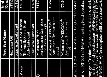
Refill Capacities, Motorcraft Parts, and Lubricant Specifications Refill Capacities NOTE: Refer to the Diesel Engine Owner’s
Guide Supplement for refill capacities on diesel engines.
377
File:ltsvf.ex Update:Thu May 9 15:30:19 1996
[SV52340( F )02/95]
thirty-six pica chart:0020504-M
378
F
t
F
t
File:ltsvf.ex Update:Thu May 9 15:30:19 1996
*[SV52675( F )05/90] *[SV52700( F )03/94]
Cooling system capacity
thirty pica chart:0020427-E
383
File:ltsvf.ex Update:Thu May 9 15:30:19 1996
*[SV52740( F )03/94]
eighteen pica chart:0020503-E
384
File:ltsvf.ex Update:Thu May 9 15:30:19 1996
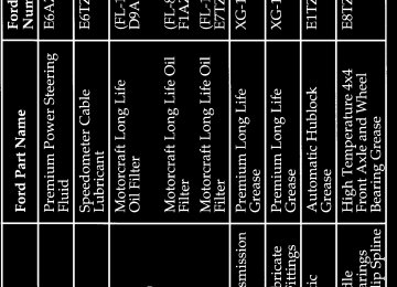
*[SV52800( ALL)01/95] [SV53300( F )05/95]
Motorcraft Parts
eighteen pica chart:0020432-P
385
F
F
t
F
t
F
File:ltsvf.ex Update:Thu May 9 15:30:19 1996
%*[SV56000( ALL)01/95] *[SV56100( ALL)01/95] *[SV56150( ALL)01/95]
*[SV56200( ALL)01/95] *[SV56300( ALL)01/95] *[SV56400( ALL)01/95] *[SV56500( ALL)01/95]
*[SV56600( ALL)01/95] *[SV56700( ALL)01/95]
*[SV56800( ALL)01/95] *[SV56900( ALL)01/95] *[SV57000( ALL)01/95]
*[SV57100( ALL)04/95] *[SV57200( ALL)01/95] *[SV57300( ALL)01/95]
Vehicle Storage Maintenance Tips If you plan on storing your vehicle for an extended period of time (60 days or more), refer to the following maintenance recommendations to ensure your vehicle stays in good operating condition. General
Store all vehicles in a dry, ventilated place.
q Protect from sunlight, if possible.
If vehicles are stored outside, they require regular maintenance to protect against rust and damage.
Body q Wash vehicle thoroughly to remove dirt,
grease, oil, tar or mud from exterior surfaces, rear wheel housing and underside of front fenders.
q Periodically wash vehicles stored in exposed
locations.
q Touch-up raw or primed metal to prevent
rust.
q Cover chrome and stainless steel parts with a
thick coat of auto wax to prevent discoloration. Re-wax as necessary when the vehicle is washed.
q Lubricate all hood, door and trunk lid hinges
and latches with a light grade oil.
q Cover interior soft trim to prevent fading. q Keep all rubber parts free from oil and
solvents.
392
File:ltsvf.ex Update:Thu May 9 15:30:19 1996
%*[SV57350( ALL)01/95] *[SV57400( ALL)01/95] *[SV57500( ALL)01/95] %*[SV57600( ALL)01/95] *[SV57700( ALL)07/94]
*[SV57900( ALL)03/95]
*[SV58000( ALL)01/95]
*[SV58050( EF )05/94]
*[SV58100( ALL)01/95]
%*[SV58200( ALL)01/95] *[SV58300( ALL)01/95]
Engine
Start engine every 15 days. Run at fast idle until it reaches normal operating temperature. q With your foot on the brake, shift through all
the gears while the engine is running.
Fuel system
Fill fuel tank with high-quality unleaded fuel until the first automatic shutoff of the fuel pump nozzle.
NOTE: During extended periods of vehicle storage (60 days or more), fuel may deteriorate due to oxidation. This can damage rubber and other polymers in the fuel system and may also clog small orifices.
Ford Gas Stabilizer should be added whenever actual or expected storage periods exceed 60
days. Follow the instructions on the label. The vehicle should then be operated at idle speed to circulate the additive throughout the fuel system. NOTE: Read the 7.3L Diesel Engine Owner Guide Supplement for information regarding vehicle storage for your diesel-powered vehicle.A volatile corrosion inhibitor added to the fuel system will protect the fuel system’s inner surfaces from corrosion. Follow the instructions packaged with the product. Cooling system q Protect against freezing temperatures.
393
File:ltsvf.ex Update:Thu May 9 15:30:19 1996
%*[SV58400( ALL)01/95] *[SV58500( ALL)01/95] *[SV58600( ALL)01/95] %*[SV58700( ALL)01/95] *[SV58800( ALL)01/95] %*[SV58900( ALL)01/95] *[SV59000(B FM)05/95] *[SV59100( ALL)01/95] *[SV59200( ALL)01/95]
*[SV59300( ALL)03/95]
Battery q Check and recharge as necessary. q Keep connections clean and covered with a
light coat of grease.
Brakes q Make sure brakes and parking brake are fully
released.
Tires q Maintain recommended air pressures. Miscellaneous q Make sure all linkages, cables, levers and clevis pins under vehicle are covered with grease to prevent rust.
q Move vehicles at least 25 feet (8 m) every 15
days to lubricate working parts to prevent corrosion.
394