- 2015 Chevrolet Camaro Owners Manuals
- Chevrolet Camaro Owners Manuals
- 2000 Chevrolet Camaro Owners Manuals
- Chevrolet Camaro Owners Manuals
- 2014 Chevrolet Camaro Owners Manuals
- Chevrolet Camaro Owners Manuals
- 1993 Chevrolet Camaro Owners Manuals
- Chevrolet Camaro Owners Manuals
- 1999 Chevrolet Camaro Owners Manuals
- Chevrolet Camaro Owners Manuals
- 1996 Chevrolet Camaro Owners Manuals
- Chevrolet Camaro Owners Manuals
- 2012 Chevrolet Camaro Owners Manuals
- Chevrolet Camaro Owners Manuals
- 2016 Chevrolet Camaro Owners Manuals
- Chevrolet Camaro Owners Manuals
- 2001 Chevrolet Camaro Owners Manuals
- Chevrolet Camaro Owners Manuals
- 2011 Chevrolet Camaro Owners Manuals
- Chevrolet Camaro Owners Manuals
- 2010 Chevrolet Camaro Owners Manuals
- Chevrolet Camaro Owners Manuals
- 1994 Chevrolet Camaro Owners Manuals
- Chevrolet Camaro Owners Manuals
- 1995 Chevrolet Camaro Owners Manuals
- Chevrolet Camaro Owners Manuals
- 2002 Chevrolet Camaro Owners Manuals
- Chevrolet Camaro Owners Manuals
- 2013 Chevrolet Camaro Owners Manuals
- Chevrolet Camaro Owners Manuals
- 1998 Chevrolet Camaro Owners Manuals
- Chevrolet Camaro Owners Manuals
- 1997 Chevrolet Camaro Owners Manuals
- Chevrolet Camaro Owners Manuals
- Download PDF Manual
-
the system: 1. Turn the ignition key to ON/RUN
with the engine off.
2. Fully press and release the
accelerator pedal three times within five seconds. If the CHANGE ENGINE OIL SOON message is not on, the system is reset.
If the CHANGE ENGINE OIL SOON message comes on again and stays on for 30 seconds at the next ignition cycle, it did not reset. The system needs to be reset again.
9-14
Vehicle Care
What to Do with Used Oil Used engine oil contains certain elements that can be unhealthy for your skin and could even cause cancer. Do not let used oil stay on your skin for very long. Clean your skin and nails with soap and water, or a good hand cleaner. Wash or properly dispose of clothing or rags containing used engine oil. See the manufacturer’s warnings about the use and disposal of oil products. Used oil can be a threat to the environment. If you change your own oil, be sure to drain all the oil from the filter before disposal. Never dispose of oil by putting it in the trash, pouring it on the ground, into sewers, or into streams or bodies of water. Recycle it by taking it to a place that collects used oil.
Automatic Transmission Fluid How to Check Automatic Transmission Fluid It is not necessary to check the transmission fluid level. A transmission fluid leak is the only reason for fluid loss. If a leak occurs, take the vehicle to your dealer/retailer service department and have it repaired as soon as possible. There is a special procedure for checking and changing the transmission fluid. Because this procedure is difficult, you should have this done at your dealer/ retailer service department.
Contact your dealer/retailer for additional information or the procedure can be found in the service manual. To purchase a service manual, see Service Publications Ordering Information on page 12-12. Change the fluid and filter at the intervals listed in Scheduled Maintenance on page 10-2, and be sure to use the fluid listed in Recommended Fluids and Lubricants on page 10-7.
Vehicle Care
9-15
How to Check and Add Fluid Visually check the brake/clutch fluid reservoir to make sure the fluid level is at the MIN (minimum) line on the side of the reservoir. The brake/hydraulic clutch fluid system should be closed and sealed. Do not remove the cap to check the fluid level or to top-off the fluid level. Remove the cap only when necessary to add the proper fluid until the level reaches the MIN line.
Manual Transmission Fluid It is not necessary to check the manual transmission fluid level. A transmission fluid leak is the only reason for fluid loss. If a leak occurs, take the vehicle to your dealer/ retailer service department and have it repaired as soon as possible. See Recommended Fluids and Lubricants on page 10-7 for the proper fluid to use.
Hydraulic Clutch It is not necessary to regularly check brake/clutch fluid unless you suspect there is a leak in the system. Adding fluid will not correct a leak. A fluid loss in this system could indicate a problem. Have the system inspected and repaired.
When to Check and What to Use
The brake/hydraulic clutch fluid reservoir cap has this symbol on it. The common hydraulic clutch and brake master cylinder fluid reservoir is filled with DOT 3 brake fluid as indicated on the reservoir cap. See Engine Compartment Overview on page 9-6 for reservoir location.
9-16
Vehicle Care
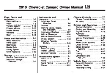
Engine Air Cleaner/Filter See Engine Compartment Overview on page 9-6 for the location of the engine air cleaner/filter. When to Inspect the Engine Air Cleaner/Filter Inspect the air cleaner/filter at the Maintenance II intervals and replace it at the first oil change after each 50,000 mile (80 000 km) interval. See “Schedule Maintenance” in Service and Maintenance for more information. If driving in dusty/dirty conditions, inspect the filter at each engine oil change.
How to Inspect the Engine Air Cleaner/Filter To inspect the air cleaner/filter, remove the filter from the vehicle and lightly shake the filter to release loose dust and dirt. If the filter remains caked with dirt, a new filter is required. To inspect or replace the engine air cleaner/filter: 1. Open the hood. See Hood on
page 9-5.
2. Locate the air filter housing
on the front of the driver side of the engine compartment. See Engine Compartment Overview on page 9-6.
3.6 L V6 Engine Air Cleaner/
Filter Housing shown
(6.2 L V8 Engines similar)
Vehicle Care
9-17
Cooling System When it is safe to lift the hood:
3. Loosen the clamp at the duct of
the air cleaner/filter housing.
{ WARNING
4. Unlatch the retaining clips on the
air cleaner/filter housing. 5. Lift cover at retaining clip
location high enough to clear retaining clips and pull cover outward to remove cover from the air cleaner/filter housing hinges.
6. Pull straight up on cover, while
holding the cover remove the air filter.
7. Inspect or replace the air filter. See Maintenance Replacement Parts on page 10-9.
8. Reverse steps 6 to 1 to install
cover.
Operating the engine with the air cleaner/filter off can cause you or others to be burned. The air cleaner not only cleans the air; it helps to stop flames if the engine backfires. If it is not there and the engine backfires, you could be burned. Do not drive with it off, and be careful working on the engine with the air cleaner/filter off.
If the air cleaner/filter
Notice: is off, a backfire can cause a damaging engine fire. And, dirt can easily get into the engine, which will damage it. Always have the air cleaner/filter in place when you are driving.
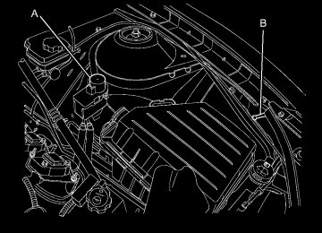
3.6 L V6 Engine A. Coolant Recovery Bottle B. Electric Cooling Fans C. Radiator Cap
(under engine cover)
9-18
Vehicle Care
6.2 L V8 Engines
(L99 shown LS3 similar)
A. Coolant Recovery Bottle B. Electric Cooling Fans C. Radiator Cap
{ WARNING
{ WARNING
An electric engine cooling fan under the hood can start up even when the engine is not running and can cause injury. Keep hands, clothing, and tools away from any underhood electric fan.
If the coolant inside the coolant recovery bottle is boiling, do not do anything else until it cools down. The vehicle should be parked on a level surface. The coolant level should be between the MIN and MAX lines. If it is not, you may have a leak at the radiator hoses, heater hoses, radiator, water pump, or somewhere else in the cooling system.
Heater and radiator hoses, and other engine parts, can be very hot. Do not touch them. If you do, you can be burned. Do not run the engine if there is a leak. If you run the engine, it could lose all coolant. That could cause an engine fire, and you could be burned. Get any leak fixed before you drive the vehicle.
If there seems to be no leak, with the engine on, check to see if the electric engine cooling fans are running. If the engine is overheating, the fans should be running. If it is not, your vehicle needs service. Turn off the engine.
What to Use
{ WARNING
Adding only plain water to the cooling system can be dangerous. Plain water, or some other liquid such as alcohol, can boil before the proper coolant mixture will. The vehicle’s coolant warning system is set for the proper coolant mixture. With plain water or the wrong mixture, the engine could get too hot but you would not get the overheat warning. The engine could catch fire and you or others could be burned. Use a 50/50 mixture of clean, drinkable water and DEX-COOL® coolant.
Notice: Using coolant other than DEX-COOL® can cause premature engine, heater core, or radiator corrosion. In addition, the engine coolant could require changing sooner, at 50 000 km (30,000 miles) or 24 months, whichever occurs first. Any repairs would not be covered by the vehicle warranty. Always use DEX-COOL® (silicate-free) coolant in the vehicle.
Engine Coolant The cooling system in the vehicle is filled with DEX-COOL® engine coolant. This coolant is designed to remain in the vehicle for five years or 240 000 km (150,000 miles), whichever occurs first. The following explains the cooling system and how to check and add coolant when it is low. If there is a problem with engine overheating, see Engine Overheating on page 9-24.
Vehicle Care
9-19
Use a 50/50 mixture of clean, drinkable water and DEX-COOL® coolant. If using this mixture, nothing else needs to be added. This mixture: • Gives freezing protection down to −37°C (−34°F), outside temperature.
• Gives boiling protection up
to 129°C (265°F), engine temperature.
• Protects against rust and
corrosion.
• Will not damage aluminum parts. • Helps keep the proper engine
temperature.
If an improper coolant
Notice: mixture is used, the engine could overheat and be badly damaged. The repair cost would not be covered by the vehicle warranty. Too much water in the mixture can freeze and crack the engine, radiator, heater core, and other parts.
9-20
Vehicle Care
Checking Coolant The vehicle must be on a level surface when checking the coolant level. Check coolant as follows: 1. Turn the ignition OFF. 2. Locate the coolant recovery
bottle. See Engine Compartment Overview on page 9-6.
3. Turn the coolant dipstick cap counterclockwise and slowly pull out the dipstick.
How to Add Coolant to the Coolant Recovery Bottle
{ WARNING
You can be burned if you spill coolant on hot engine parts. Coolant contains ethylene glycol and it will burn if the engine parts are hot enough. Do not spill coolant on a hot engine.
If an improper coolant
Notice: This vehicle has a specific coolant fill procedure. Failure to follow this procedure could cause the engine to overheat and be severely damaged. Notice: mixture is used, the engine could overheat and be badly damaged. The repair cost would not be covered by the vehicle warranty. Too much water in the mixture can freeze and crack the engine, radiator, heater core, and other parts.
4. There are maximum and minimum markings on the dipstick. When the engine is cold, the coolant level should be at or above the MIN mark on the dipstick. After the vehicle has been driven and the engine is at normal operating temperature, the level should be somewhere between half full and the maximum mark. If the coolant level is correct, replace the dipstick and turn the cap clockwise to secure.
5.
Notice: This vehicle has a specific coolant fill procedure. Failure to follow this procedure could cause the engine to overheat and be severely damaged.
{ WARNING
An electric engine cooling fan under the hood can start up even when the engine is not running and can cause injury. Keep hands, clothing, and tools away from any underhood electric fan.
Add coolant as follows: 1. Turn the coolant overflow bottle
dipstick cap counterclockwise and slowly pull out the dipstick.
2. Pour the coolant into the coolant
recovery bottle.
3. When the level is correct,
replace the dipstick and turn the cap clockwise to secure. How to Add Coolant to the Radiator
{ WARNING
You can be burned if you spill coolant on hot engine parts. Coolant contains ethylene glycol and it will burn if the engine parts are hot enough. Do not spill coolant on a hot engine.
Vehicle Care
9-21
{ WARNING
Steam and scalding liquids from a hot cooling system can blow out and burn you badly. They are under pressure, and if you turn the surge tank pressure cap — even a little — they can come out at high speed. Never turn the cap when the cooling system, including the surge tank pressure cap, is hot. Wait for the cooling system and surge tank pressure cap to cool if you ever have to turn the pressure cap.
If coolant is needed, add the proper mixture directly to the radiator, but be sure the cooling system is cool before this is done.
9-22
Vehicle Care
If no coolant is visible in the coolant overflow bottle, add coolant as follows:
3.6 L V6 Engine Fill Procedure 1. Locate the radiator cap.
See Engine Compartment Overview on page 9-6.
2. Remove engine cover to access
the radiator cap. See Engine Cover on page 9-9.
3. Cover the radiator cap with a
thick cloth and turn it slowly counterclockwise and remove. 4. If there is no coolant visible or the level is low, slowly fill the system through the radiator cap opening with a 50/50 mixture of DEX-COOL® and clean drinkable water.
Wait 30 seconds for coolant to settle and continue filling if the level drops. Do not spill coolant on the accessory drive belts. If a spill occurs, rinse the belt with fresh water. 5. Start the engine. 6. With the engine idling, continue
to add coolant through the radiator cap opening until full. Wait 30 seconds for the coolant to settle and top off, if the level drops.
7. Once the system is full, put the radiator cap back on by turning clockwise.
8. With the engine still running, raise the engine to 2500 RPM for 30–40 seconds.
9. Turn the engine OFF. 10. Repeat steps 2–7 then turn the
engine off.
11. Allow engine to cool for
45 minutes. Top off coolant through the radiator cap opening and re-install the radiator cap.
12. Re-install the engine cover.
See Engine Cover on page 9-9.
13. Check the coolant level in the coolant recovery bottle and fill it until the level is at the top symbol on the dipstick.
6.2 L V8 Engine Fill Procedure 1. Locate the radiator cap.
See Engine Compartment Overview on page 9-6.
2. Cover the radiator cap with a
thick cloth and turn it slowly counterclockwise and remove. 3. If there is no coolant visible or the level is low, slowly fill the system through the radiator cap opening with a 50/50 mixture of clean, drinkable water and a DEX-COOL® coolant until full.
Wait 30 seconds for coolant to settle and top off if the level drops. Do not spill coolant on the accessory drive belts. If a spill occurs, rinse the belt with fresh water. 4. Start the engine. 5. With the engine idling, top off the coolant through the radiator cap opening until full. Wait 30 seconds for the coolant to settle and top off, if the level drops.
6. Once the system is full, put the radiator cap back on by turning clockwise.
7. Turn the engine OFF.
Vehicle Care
9-23
8. Check the coolant level in the coolant recovery bottle and fill it until the level is at the top mark on the dipstick.
If the pressure cap is
Notice: not tightly installed, coolant loss and possible engine damage may occur. Be sure the cap is properly and tightly secured.
9-24
Vehicle Care
Engine Overheating The vehicle has an indicator to warn of engine overheating. There is an engine coolant temperature warning light on your vehicle’s instrument panel. See Engine Coolant Temperature Gage on page 4-14. You may decide not to lift the hood when this warning appears, but instead get service help right away. See Roadside Assistance Program on page 12-6. If you do decide to lift the hood, make sure the vehicle is parked on a level surface.
Then check to see if the engine cooling fans are running. If the engine is overheating, both fans should be running. If they are not, do not continue to run the engine and have the vehicle serviced. Notice: Engine damage from running the engine without coolant is not covered by the warranty. Notice: fire because of being driven with no coolant, your vehicle can be badly damaged. The costly repairs would not be covered by the vehicle warranty.
If the engine catches
If Steam Is Coming From The Engine Compartment { WARNING
Steam from an overheated engine can burn you badly, even if you just open the hood. Stay away from the engine if you see or hear steam coming from it. Just turn it off and get everyone away from the vehicle until it cools down. Wait until there is no sign of steam or coolant before you open the hood. If you keep driving when your engine is overheated, the liquids in it can catch fire. You or others could be badly burned. Stop your engine if it overheats, and get out of the vehicle until the engine is cool.
If No Steam Is Coming From The Engine Compartment If an engine overheat warning is displayed but no steam can be seen or heard, the problem may not be too serious. Sometimes the engine can get a little too hot when the vehicle: • Climbs a long hill on a hot day. • Stops after high-speed driving. • Idles for long periods in traffic. • Tows a trailer. If the overheat warning is displayed with no sign of steam: 1. Turn the air off. 2. Turn the heater on to the highest
temperature and to the highest fan speed. Open the windows as necessary.
3.
In heavy traffic, let the engine idle in N (Neutral) while stopped. If it is safe to do so, pull off the road, shift to P (Park) or N (Neutral) and let the engine idle.
If the temperature overheat gage is no longer in the overheat zone or an overheat warning no longer displays, the vehicle can be driven. Continue to drive the vehicle slow for about 10 minutes. Keep a safe vehicle distance from the car in front of you. If the warning does not come back on, continue to drive normally. If the warning continues, pull over, stop, and park the vehicle right away. If there is no sign of steam, idle the engine for three minutes while parked. If the warning is still displayed, turn off the engine until it cools down. Also, see “Overheated Engine Protection Operating Mode” later in this section.
Vehicle Care
9-25
Power Steering Fluid
The power steering fluid reservoir is located under the engine cover on the driver side toward the front of the engine compartment. See Engine Compartment Overview on page 9-6. When to Check Power Steering Fluid It is not necessary to regularly check power steering fluid unless you suspect there is a leak in the system or an unusual noise is heard. A fluid loss in this system could indicate a problem. Have the system inspected and repaired.
9-26
Vehicle Care
How to Check Power Steering Fluid Check the level after the vehicle has been driven for at least twenty minutes so the fluid is warm. To check the power steering fluid: 1. Turn the ignition key to
LOCK/OFF and let the engine compartment cool down.
2. Remove the engine cover. Refer
to Engine Cover on page 9-9.
3. Wipe the cap and the top of the
reservoir clean.
4. Turn the cap counterclockwise
and pull it straight up.
5. Wipe the dipstick with a
clean rag.
6. Replace the cap and completely
tighten it.
7. Remove the cap again and look at the fluid level on the dipstick.
When the engine is hot, the level should be at the hot MAX level. When the engine is cold, the fluid level should be between MIN and MAX on the dipstick.
What to Use To determine what kind of fluid to use, see Recommended Fluids and Lubricants on page 10-7. Always use the proper fluid.
Washer Fluid What to Use When windshield washer fluid is needed, be sure to read the manufacturer’s instructions before use. If operating vehicle in an area where the temperature can fall below freezing, use a fluid that has sufficient protection against freezing.
Adding Washer Fluid
Open the cap with the washer symbol on it. Add washer fluid until the reservoir is full. See Engine Compartment Overview on page 9-6
for reservoir location.Notice: (cid:129) When using concentrated
washer fluid, follow the manufacturer’s instructions for adding water.
(cid:129) Do not mix water with
ready-to-use washer fluid. Water can cause the solution to freeze and damage your washer fluid tank and other parts of the washer system. Also, water does not clean as well as washer fluid. Fill the washer fluid tank only three-quarters full when it is very cold. This allows for fluid expansion if freezing occurs, which could damage the tank if it is completely full.
(cid:129) Do not use engine coolant
(antifreeze) in your windshield washer. It can damage the vehicle’s windshield washer system and paint.
Brakes This vehicle has disc brakes. Disc brake pads have built-in wear indicators that make a high-pitched warning sound when the brake pads are worn and new pads are needed. The sound can come and go or be heard all the time the vehicle is moving, except when applying the brake pedal firmly.
{ WARNING
The brake wear warning sound means that soon the brakes will not work well. That could lead to an accident. When the brake wear warning sound is heard, have the vehicle serviced.
Notice: Continuing to drive with worn-out brake pads could result in costly brake repair.
Vehicle Care
9-27
Some driving conditions or climates can cause a brake squeal when the brakes are first applied or lightly applied. This does not mean something is wrong with the brakes. Properly torqued wheel nuts are necessary to help prevent brake pulsation. When tires are rotated, inspect brake pads for wear and evenly tighten wheel nuts in the proper sequence to torque specifications in Capacities and Specifications on page 11-2. Brake linings should always be replaced as complete axle sets.
Brake Pedal Travel See your dealer/retailer if the brake pedal does not return to normal height, or if there is a rapid increase in pedal travel. This could be a sign that brake service might be required.
(cid:129) 9-28
Vehicle Care
Brake Adjustment Every time the brakes are applied, with or without the vehicle moving, the brakes adjust for wear.
Replacing Brake System Parts The braking system on a vehicle is complex. Its many parts have to be of top quality and work well together if the vehicle is to have really good braking. The vehicle was designed and tested with top-quality brake parts. When parts of the braking system are replaced, be sure to get new, approved replacement parts. If this is not done, the brakes might not work properly. For example, installing disc brake pads that are wrong for the vehicle, can change the balance between the front and rear brakes —for the worse. The braking performance expected can change in many other ways if the wrong replacement brake parts are installed.
Brake Fluid
The brake/clutch master cylinder reservoir is filled with DOT 3 brake fluid as indicated on the reservoir cap. See Engine Compartment Overview on page 9-6 for the location of the reservoir. There are only two reasons why the fluid level in the reservoir might go down: • The fluid level goes down
because of normal brake lining wear. When new linings are installed, the fluid level goes back up.
• A fluid leak in the brake/clutch
hydraulic system can also cause a low fluid level. Have the brake/clutch hydraulic system fixed, since a leak means that sooner or later the brakes and/or clutch will not work well.
Do not top off the brake/clutch fluid. Adding fluid does not correct a leak. If fluid is added when the linings are worn, there will be too much fluid when new brake linings are installed. Add or remove brake fluid, as necessary, only when work is done on the brake/clutch hydraulic system.
{ WARNING
If too much brake fluid is added, it can spill on the engine and burn, if the engine is hot enough. You or others could be burned, and the vehicle could be damaged. Add brake fluid only when work is done on the brake/clutch hydraulic system.
When the brake/clutch fluid falls to a low level, the brake warning light comes on. See Brake System Warning Light on page 4-22.
What to Add Use only new DOT 3 brake fluid from a sealed container. See Recommended Fluids and Lubricants on page 10-7. Always clean the brake/clutch fluid reservoir cap and the area around the cap before removing it. This helps keep dirt from entering the reservoir.
{ WARNING
With the wrong kind of fluid in the brake/clutch hydraulic system, the brakes might not work well. This could cause a crash. Always use the proper brake/clutch fluid.
Notice: (cid:129) Using the wrong fluid can badly damage brake/clutch hydraulic system parts. For example, just a few drops of mineral-based oil, such as engine oil, in the brake hydraulic system can damage brake hydraulic system parts so badly that they will have to be replaced. Do not let someone put in the wrong kind of fluid. If brake fluid is spilled on the vehicle’s painted surfaces, the paint finish can be damaged. Be careful not to spill brake fluid on the vehicle. If you do, wash it off immediately.
Vehicle Care
9-29
Battery This vehicle has a maintenance free battery. When it is time for a new battery, see your dealer/retailer for one that has the replacement number shown on the original battery’s label. See Engine Compartment Overview on page 9-6 for battery location. { WARNING
Battery posts, terminals, and related accessories contain lead and lead compounds, chemicals known to the State of California to cause cancer and reproductive harm. Wash hands after handling.
(cid:129) 9-30
Vehicle Care
Vehicle Storage
{ WARNING
Batteries have acid that can burn you and gas that can explode. You can be badly hurt if you are not careful. See Jump Starting on page 9-84 for tips on working around a battery without getting hurt.
Infrequent Usage: If the vehicle is driven infrequently, remove the black, negative (−) cable from the battery. This helps keep the battery from running down.
Extended Storage: For extended storage of the vehicle, remove the black, negative (−) cable from the battery or use a battery trickle charger. This helps maintain the charge of the battery over an extended period of time.
Rear Axle When to Check Lubricant It is not necessary to regularly check rear axle fluid unless you suspect there is a leak or you hear an unusual noise. A fluid loss could indicate a problem. Have it inspected and repaired.
How to Check Lubricant
V6 Automatic Transmission
shown, V6 Manual Transmission,
V8 Automatic and Manual
transmission similar
A. Fill Plug Hole B. Drain Plug Hole
To get an accurate reading, the vehicle should be on a level surface. If the level is below the bottom of the filler plug hole, add some lubricant. Add enough lubricant to raise the level to the bottom of the filler plug hole.
Starter Switch Check
{ WARNING When you are doing this inspection, the vehicle could move suddenly. If the vehicle moves, you or others could be injured.
1. Before starting this check,
be sure there is enough room around the vehicle.
2. Firmly apply both the parking brake and the regular brake. See Parking Brake on page 8-32. Do not use the accelerator pedal, and be ready to turn off the engine immediately if it starts.
Vehicle Care
9-31
3. For automatic transmission
vehicles, try to start the engine in each gear. The vehicle should start only in P (Park) or N (Neutral). If the vehicle starts in any other position, contact your dealer/retailer for service. For manual transmission vehicles, put the shift lever in Neutral, push the clutch pedal down halfway, and try to start the engine. The vehicle should start only when the clutch pedal is pushed down all the way to the floor. If the vehicle starts when the clutch pedal is not pushed all the way down, contact your dealer/retailer for service.
What to Use For 218 mm rear drive module (RDM) V6 manual, V8 automatic and V8 manual: To add lubricant when the level is low, use 75W-90 LS gear oil (GM Part No. US 89021677
and 1052358, in Canada Part No. 89021678 and 992694) meeting GM Specification 9986226. To completely refill after draining, see Recommended Fluids and Lubricants on page 10-7. Then fill to the bottom of the filler plug hole with the Synthetic Gear Lubricant. For 195 mm RDM V6 automatic: To add lubricant when the level is low, use 75W-90 gear Oil (GM Part No. US 89021677, in Canada Part No. 89021678) meeting GM Specification 9986115. To completely refill after draining, see Recommended Fluids and Lubricants on page 10-7. Then fill to the bottom of the filler plug hole with the Synthetic Gear Lubricant.9-32
Vehicle Care
Automatic Transmission Shift Lock Control System Check
{ WARNING When you are doing this inspection, the vehicle could move suddenly. If the vehicle moves, you or others could be injured.
1. Before starting this check, be
sure there is enough room around the vehicle. It should be parked on a level surface.
2. Firmly apply the parking brake.
See Parking Brake on page 8-32. Be ready to apply the regular brake immediately if the vehicle begins to move.
3. With the engine off, turn the ignition to ON/RUN, but do not start the engine. Without applying the regular brake, try to move the shift lever out of P (Park) with normal effort. If the shift lever moves out of P (Park), contact your dealer/retailer for service.
Ignition Transmission Lock Check While parked, and with the parking brake set, try to turn the ignition to LOCK/OFF in each shift lever position. • The ignition should turn to LOCK/OFF only when the shift lever is in P (Park).
• The ignition key should come out
only in LOCK/OFF.
Contact your dealer/retailer if service is required.
Park Brake and P (Park) Mechanism Check { WARNING
When you are doing this check, the vehicle could begin to move. You or others could be injured and property could be damaged. Make sure there is room in front of the vehicle in case it begins to roll. Be ready to apply the regular brake at once should the vehicle begin to move.
Wiper Blade Replacement Windshield wiper blades should be inspected for wear and cracking. See Scheduled Maintenance on page 10-2 for more information. Replacement blades come in different types and are removed in different ways. For proper type and length, see Maintenance Replacement Parts on page 10-9.
Park on a fairly steep hill, with the vehicle facing downhill. Keeping your foot on the regular brake, set the parking brake. • To check the parking brake’s
holding ability: With the engine running and the transmission in N (Neutral), slowly remove foot pressure from the regular brake pedal. Do this until the vehicle is held by the parking brake only.
• To check the P (Park)
mechanism’s holding ability: With the engine running, shift to P (Park). Then release the parking brake followed by the regular brake.
Contact your dealer/retailer if service is required.
Vehicle Care
9-33
To replace the windshield wiper blade: 1. Pull the windshield wiper assembly away from the windshield.
2. Lift up on the latch in the middle
of the wiper blade where the wiper arm attaches.
9-34
Vehicle Care
3. With the latch open, pull the
wiper blade down towards the windshield far enough to release it from the J-hooked end of the wiper arm.
4. Remove the wiper blade.
Allowing the wiper blade arm to touch the windshield when no wiper blade is installed could damage the windshield. Any damage that occurs would not be covered by the vehicle warranty. Do not allow the wiper blade arm to touch the windshield.
5. Reverse steps 1 through 3 for
wiper blade replacement.
Headlamp Aiming The headlamp aiming system has been preset at the factory. If the vehicle is damaged in an accident, the aim of the headlamps may be affected and adjustment may be necessary. It is recommended that a dealer/retailer adjust the headlamps. To re-aim the headlamps yourself, use the following procedure. The vehicle should be properly prepared as follows: • The vehicle should be placed so the headlamps are 7.6 m (25 ft) from a light colored wall.
• The vehicle must have all four tires on a level surface which is level all the way to the wall.
• The vehicle should be placed so it is perpendicular to the wall or other flat surface.
• The vehicle should not have any
snow, ice, or mud on it.
• The vehicle should be fully
assembled and all other work stopped while headlamp aiming is being performed.
• The vehicle should be normally loaded with a full tank of fuel and one person or 75 kg (160 lbs) sitting on the driver’s seat.
• Tires should be properly inflated. Headlamp aiming is done with the vehicle’s low-beam headlamps. The high-beam headlamps will be correctly aimed if the low-beam headlamps are aimed properly.
To adjust the vertical aim: 1. Open the hood. See Hood on page 9-5 for more information.
Vehicle Care
9-35
Halogen Headlamp
HID Headlamp
2. Locate the aim dot on the lens of
the low-beam headlamp.
3. Measure the distance from the
ground to the aim dot on the low-beam headlamp. Record the distance.
4. At the wall measure from
the ground upward (A) to the recorded distance from Step 3
and mark it.5. Draw or tape a horizontal line (B)
on the wall the width of the vehicle at the height of the mark in Step 4.
9-36
Vehicle Care
Notice: Do not cover a headlamp to improve beam cut-off when aiming. Covering a headlamp may cause excessive heat build-up which may cause damage to the headlamp. 6. Turn on the low-beam
headlamps and place a piece of cardboard or equivalent in front of the headlamp not being adjusted. This allows only the beam of light from the headlamp being adjusted to be seen on the flat surface.
Halogen Headlamp
HID Headlamp
7. Locate the vertical headlamp
aiming screws, which are under the hood near each headlamp assembly. The adjustment screw can be turned with a 6 mm hex key.
8. Turn the vertical aiming screw
until the headlamp beam is aimed to the horizontal tape line. Turn it clockwise or counterclockwise to raise or lower the angle of the beam.
9. Make sure that the light from the headlamp is positioned at the bottom edge of the horizontal tape line. The lamp on the left (A) shows the correct headlamp aim. The lamp on the right (B) shows the incorrect headlamp aim.
10. Repeat Steps 6 through 9 for
the opposite headlamp.
Bulb Replacement For the proper type of replacement bulbs, see Replacement Bulbs on page 9-41. For any bulb changing procedure not listed in this section, contact your dealer/retailer.
Halogen Bulbs
{ WARNING
Halogen bulbs have pressurized gas inside and can burst if you drop or scratch the bulb. You or others could be injured. Be sure to read and follow the instructions on the bulb package.
High Intensity Discharge (HID) Lighting
{ WARNING
The low beam high intensity discharge lighting system operates at a very high voltage. If you try to service any of the system components, you could be seriously injured. Have your dealer/retailer or a qualified technician service them.
The up–level vehicle is equipped with HID headlamps. The park lamp function is also a function of the HID headlamp. After an HID headlamp bulb has been replaced, you may notice that the beam is a slightly different shade than it was originally. This is normal.
Vehicle Care
9-37
Headlamps, Front Turn Signal and Parking Lamps (Base Vehicle) The base model vehicle has a halogen headlamp and a turn signal/parking lamp on the headlamp assembly. To replace one of these bulbs: 1. Open the hood. See Hood on
page 9-5.
2. Press in on the tabs located on
the sides of the duct and then push the duct rearward into the air cleaner/filter housing.
9-38
Vehicle Care
A. Parking/Turn Signal Lamp B. Halogen Headlamp
3. Disconnect the wiring harness
and turn the bulb socket counterclockwise to remove it from the headlamp assembly.
4. Pull the bulb straight out from the
socket.
5. Push the new bulb into the
socket and reinstall the socket into the headlamp assembly by turning it clockwise.
6. Reconnect the electrical
connector.
7. Pull the duct back out of the air cleaner/filter housing until the tabs snap the duct back into position.
Headlamps, Front Turn Signal and Parking Lamps (Up-Level Vehicle) The up–level model vehicle has a HID headlamp and a turn signal lamp on the headlamp assembly. The park lamp is also the function of the HID headlamp. See High Intensity Discharge (HID) Lighting on page 9-37 for more information.
To replace the turn signal bulb: 1. Open the hood. See Hood
on page 9-5.
2. Press in on the tabs located on
the sides of the duct and then push the duct rearward into the air cleaner/filter housing.
Daytime Running Lamps (DRL) The up-level model vehicle may have daytime running lamps which would be located on the facia. To replace one of these bulbs:
Vehicle Care
9-39
3. Push in the new bulb assembly
to lock it into place.
4. Reconnect the electrical
connector to the bulb assembly.
The base model vehicle daytime running lamps are the low beam on the halogen headlamp. If one these lamps fail, see Headlamps, Front Turn Signal and Parking Lamps (Base Vehicle) on page 9-37
or Headlamps, Front Turn Signal and Parking Lamps (Up-Level Vehicle) on page 9-38 for replacement information.1. Locate the bulb assembly under
the front facia.
2. Disconnect the electrical connector from the bulb assembly and pull out the bulb assembly.
3. Disconnect the wiring harness
and turn the bulb socket counterclockwise to remove it from the headlamp assembly.
4. Pull the bulb straight out from the
socket.
5. Push the new bulb into the
socket and reinstall the socket into the headlamp assembly by turning it clockwise.
6. Reconnect the electrical
connector.
7. Pull the duct back out of the air cleaner/filter housing until the tabs snap the duct back into position.
9-40
Vehicle Care
Fog Lamps The base model vehicle may have fog lamps which would be located on the facia. To replace one of these bulbs:
The up-level vehicle will not be equipped with fog lamps.
Taillamps, Turn Signal, and Stoplamps To replace a taillamp, turn signal, or stoplamp bulb: 1. Open the trunk. See Trunk on
page 1-8.
4. Pull the old bulb straight out of
the bulb socket.
5. Push the new bulb straight into
the bulb socket until it clicks.
6. Turn the bulb socket clockwise to
reinstall.
License Plate Lamp To replace one of these bulbs:
1. Locate the bulb assembly under
the front facia.
2. Disconnect the electrical connector from the bulb assembly and pull out the bulb assembly.
3. Push in the new bulb assembly
to lock it into place.
4. Reconnect the electrical
connector to the bulb assembly.
2. Remove the close out panel
retainers to gain access to the bulb socket connectors.
3. Turn the bulb socket
counterclockwise to remove it.
1. Unclip the license plate lamp
from the facia opening.
2. Pull the license plate lamp down
through the facia opening.
3. Turn the bulb socket
counterclockwise and pull the bulb straight out of the lamp socket.
4. Install the new bulb. 5. Push the bulb straight into the
socket and turn clockwise to reinstall.
6. Reinstall the license plate lamp
by lifting it through the facia opening until the clip is in place.
Replacement Bulbs
Exterior Lamp
Daytime Running Lamp (Up-level vehicles) Fog Lamp Front Park and Turn Signal Lamp Halogen Headlamp License Plate Lamp Rear Turn Signal and Taillamps
Bulb
Number
P13W
PS24W
3457NAK
H13
W5W3157K
For replacement bulbs not listed here, contact your dealer/retailer.
Vehicle Care
9-41
Electrical System Electrical System Overload The vehicle has fuses and circuit breakers to protect against an electrical system overload. When the current electrical load is too heavy, the circuit breaker opens and closes, protecting the circuit until the current load returns to normal or the problem is fixed. This greatly reduces the chance of circuit overload and fire caused by electrical problems. Fuses and circuit breakers protect the following in the vehicle: • Headlamp Wiring • Windshield Wiper Motor • Power Windows and other Power
Accessories
9-42
Vehicle Care
Headlamp Wiring An electrical overload may cause the lamps to go on and off, or in some cases to remain off. Have the headlamp wiring checked right away if the lamps go on and off or remain off.
Windshield Wipers If the wiper motor overheats due to heavy snow or ice, the windshield wipers will stop until the motor cools and will then restart. Although the circuit is protected from electrical overload, overload due to heavy snow or ice, may cause wiper linkage damage. Always clear ice and heavy snow from the windshield before using the windshield wipers. If the overload is caused by an electrical problem and not snow or ice, be sure to get it fixed.
Fuses and Circuit Breakers The wiring circuits in the vehicle are protected from short circuits by a combination of fuses and circuit breakers. This greatly reduces the chance of damage caused by electrical problems. To check a fuse, look at the silver-colored band inside the fuse. If the band is broken or melted, replace the fuse. Be sure to replace a bad fuse with a new one of the identical size and rating. Fuses of the same amperage can be temporarily borrowed from another fuse location, if a fuse goes out. Replace the fuse as soon as possible. To identify and check fuses, circuit breakers, and relays, see Engine Compartment Fuse Block on page 9-42, Instrument Panel Fuse Block on page 9-45, and Rear Compartment Fuse Block on page 9-46.
Engine Compartment Fuse Block
To remove the hinged fuse block cover, press the clip at the front of the cover, and swing it up. Notice: Spilling liquid on any electrical components on the vehicle may damage it. Always keep the covers on any electrical component.
Vehicle Care
9-43
J-Case Fuses
41
42
43
44
Usage
Cooling Fan High Front Heater, Ventilation and Air Conditioning Antilock Brake System Pump Cooling Fan Low
Mini Fuses
Usage
10
Air Conditioning Compressor Clutch Transmission Control Module Engine Control Module Main Pre-Catalytic Converter Oxygen Sensor Post-Catalytic Converter Oxygen Sensor Fuel Injectors – Even Fuel Injectors – Odd
Engine Compartment Fuse Block
J-Case Fuses
12
22
Usage
Wiper Starter Brake Vacuum Pump
J-Case Fuses
25
26
27
Usage
Power Windows Rear Power Windows Front Rear Defog
9-44
Vehicle Care
Mini Fuses
Usage
Mini Fuses
Usage
11
14
15
1617
18
19
20
31
32
33
Cooling Fan Relay Manifold Air Flow/Chassis Control Ignition Run/Crank IP Sensing Diagnostic Module/Ignition Run/Crank Body Transmission Control Module/ Ignition Engine Control Module/Ignition Outside Rear View Mirror Canister Vent Solenoid Body Control Module #6
34
35
3840
46
47
50
51
5255
56
61
Sunroof Front Heated Seats Washer Pump Front Antilock Brake System Valves HID Headlamp – Left Front HID Headlamp – Right Front Fog Lamps Horn Spare High Beam Headlamp – Right Front High Beam Headlamp – Left Front Heated Mirror
Mini
Relays
K26
K50
K55
K612
K614Micro Relays
K61
K69
K613K617
K619
K627
K632
Usage
Powertrain Run / Crank Rear Defog Cooling Fan High Cooling Fan Control
Usage
Starter Wiper Control Cooling Fan Low Air Conditioning Compressor Clutch Wiper Speed High Intensity Discharge Headlamps Brake Vacuum Pump
Instrument Panel Fuse Block
Vehicle Care
9-45
The instrument panel fuse block is located on the end of the instrument panel, on the driver side of the vehicle. To access the fuses, open the fuse panel door by pulling out. To reinstall the door, push the door back into its original location.
Instrument Panel Fuse Block
Fuses
F1
F2
F3
F4Usage Discrete Logic Ignition Switch Diagnostic Link Connector Airbag Cluster
Fuses
Usage
F5
F6
F8
F9Heating Ventilation Air Conditioning Controller Body Control Module Battery Spare
9-46
Vehicle Care
Usage
Fuses
Fuses F10
F11
F12
F13F14
F15
F16
F17
F18F19
F20
F21
F22
F23F24
Spare Spare Spare Display OnStar® Universal Hands Free Phone Body Control Module 3
Body Control Module 4
Power Outlet 1
Power Outlet 2
Steering Wheel Controls Backlight Spare Spare Spare Trunk Automatic Occupant SensingRear Compartment Fuse Block
Usage Body Control Module 1
Body Control Module 8
Spare Body Control Module 5
Body Control Module 7F25
F27
F28
F29
F30
Circuit Breakers
CB7
CB26Usage
Passenger Seat Driver Seat
Relays
Usage
K10
K605
K609Retained Accessory Power Not Used Trunk
The rear compartment fuse block is located on the right side of the trunk behind a cover. Remove the six convenience net retainers, the rear sill plate, and the two passenger side trim retainers, then swing the trim out of the way.
Vehicle Care
9-47
Fuses
Usage
F9
F10
F11
F12F13
F14
F15
F16
Spare Spare Spare Spare Engine Control Module/Battery Regulated Voltage Control Fuel System Control Module Spare
Fuses
Usage
Fuses
Usage
Universal Garage Door Opener/ Ultrasonic Reverse Parking Aid Amplifier Radio
F1
F2
F3F4
F5
F6
F7
F8Spare Convertible Top 1
Convertible Top 2
Spare Spare9-48
Vehicle Care
Wheels and Tires Tires Your new vehicle comes with high-quality tires made by a leading tire manufacturer. If you ever have questions about your tire warranty and where to obtain service, see your vehicle Warranty booklet for details. For additional information refer to the tire manufacturer. { WARNING
Poorly maintained and improperly used tires are dangerous.
• Overloading your tires can
cause overheating as a result of too much flexing. You could have an air-out and a serious accident. See Vehicle Load Limits on page 8-12.
(Continued)
WARNING (Continued)
• Underinflated tires pose the same danger as overloaded tires. The resulting accident could cause serious injury. Check all tires frequently to maintain the recommended pressure. Tire pressure should be checked when your tires are cold. See Tire Pressure on page 9-54.
• Overinflated tires are more likely to be cut, punctured or broken by a sudden impact — such as when you hit a pothole. Keep tires at the recommended pressure.
• Worn, old tires can cause accidents. If your tread is badly worn, or if your tires have been damaged, replace them.
Winter Tires If you expect to drive on snow or ice covered roads often, you may want to get winter tires for your vehicle. All season tires provide good overall performance on most surfaces but they may not offer the traction you would like or the same level of performance as winter tires on snow or ice covered roads. Winter tires, in general, are designed for increased traction on snow and ice covered roads. With winter tires, there may be decreased dry road traction, increased road noise, and shorter tread life. After switching to winter tires, be alert for changes in vehicle handling and braking. See your dealer/retailer for details regarding winter tire availability and proper tire selection. Also, see Buying New Tires on page 9-63.
If you choose to use winter tires: • Use tires of the same brand and
tread type on all four wheel positions.
• Use only radial ply tires of the
same size, load range, and speed rating as the original equipment tires.
Winter tires with the same speed rating as your original equipment tires may not be available for H, V, W, Y, and ZR speed rated tires. If you choose winter tires with a lower speed rating, never exceed the tire’s maximum speed capability.
Tire Sidewall Labeling Useful information about a tire is molded into its sidewall. The examples below show a typical passenger vehicle tire and a compact spare tire sidewall.
Passenger (P-Metric)
Tire Example
(A) Tire Size: The tire size is a combination of letters and numbers used to define a particular tire’s width, height, aspect ratio, construction type, and service description. See the “Tire Size” illustration later in this section for more detail.
Vehicle Care
9-49
(B) TPC Spec (Tire Performance Criteria Specification): Original equipment tires designed to GM’s specific tire performance criteria have a TPC specification code molded onto the sidewall. GM’s TPC specifications meet or exceed all federal safety guidelines. (C) DOT (Department of Transportation): The Department of Transportation (DOT) code indicates that the tire is in compliance with the U.S. Department of Transportation Motor Vehicle Safety Standards.
9-50
Vehicle Care
(D) Tire Identification Number (TIN): The letters and numbers following the DOT (Department of Transportation) code is the Tire Identification Number (TIN). The TIN shows the manufacturer and plant code, tire size, and date the tire was manufactured. The TIN is molded onto both sides of the tire, although only one side may have the date of