- 2015 Chevrolet Camaro Owners Manuals
- Chevrolet Camaro Owners Manuals
- 2000 Chevrolet Camaro Owners Manuals
- Chevrolet Camaro Owners Manuals
- 2014 Chevrolet Camaro Owners Manuals
- Chevrolet Camaro Owners Manuals
- 1993 Chevrolet Camaro Owners Manuals
- Chevrolet Camaro Owners Manuals
- 1999 Chevrolet Camaro Owners Manuals
- Chevrolet Camaro Owners Manuals
- 1996 Chevrolet Camaro Owners Manuals
- Chevrolet Camaro Owners Manuals
- 2012 Chevrolet Camaro Owners Manuals
- Chevrolet Camaro Owners Manuals
- 2016 Chevrolet Camaro Owners Manuals
- Chevrolet Camaro Owners Manuals
- 2001 Chevrolet Camaro Owners Manuals
- Chevrolet Camaro Owners Manuals
- 2011 Chevrolet Camaro Owners Manuals
- Chevrolet Camaro Owners Manuals
- 2010 Chevrolet Camaro Owners Manuals
- Chevrolet Camaro Owners Manuals
- 1994 Chevrolet Camaro Owners Manuals
- Chevrolet Camaro Owners Manuals
- 1995 Chevrolet Camaro Owners Manuals
- Chevrolet Camaro Owners Manuals
- 2002 Chevrolet Camaro Owners Manuals
- Chevrolet Camaro Owners Manuals
- 2013 Chevrolet Camaro Owners Manuals
- Chevrolet Camaro Owners Manuals
- 1998 Chevrolet Camaro Owners Manuals
- Chevrolet Camaro Owners Manuals
- 1997 Chevrolet Camaro Owners Manuals
- Chevrolet Camaro Owners Manuals
- Download PDF Manual
-
2-42
Seats and Restraints
A label on the sun visor says, “Never put a rear-facing child restraint in the front.” This is because the risk to the rear-facing child is so great, if the airbag deploys.
{ WARNING
A child in a rear-facing child restraint can be seriously injured or killed if the right front passenger airbag inflates. This is because the back of the rear-facing child restraint would be very close to the inflating airbag. A child in a forward-facing child restraint can be seriously injured or killed if the right front passenger airbag inflates and the passenger seat is in a forward position.
(Continued)
WARNING (Continued)
Even if the passenger sensing system has turned off the right front passenger frontal airbag, no system is fail-safe. No one can guarantee that an airbag will not deploy under some unusual circumstance, even though it is turned off. Secure rear-facing child restraints in a rear seat, even if the airbag is off. If you secure a forward-facing child restraint in the right front seat, always move the front passenger seat as far back as it will go. It is better to secure the child restraint in a rear seat. See Passenger Sensing System on page 2-28 for additional information.
When securing a child restraint in a rear seating position, study the instructions that came with the child restraint to make sure it is compatible with this vehicle. Wherever a child restraint is installed, be sure to secure the child restraint properly. Keep in mind that an unsecured child restraint can move around in a collision or sudden stop and injure people in the vehicle. Be sure to properly secure any child restraint in the vehicle — even when no child is in it.
Lower Anchors and Tethers for Children (LATCH System) The LATCH system holds a child restraint during driving or in a crash. This system is designed to make installation of a child restraint easier. The LATCH system uses anchors in the vehicle and attachments on the child restraint that are made for use with the LATCH system. Make sure that a LATCH-compatible child restraint is properly installed using the anchors, or use the vehicle’s safety belts to secure the restraint, following the instructions that came with that restraint, and also the instructions in this manual. When installing a child restraint with
a top tether, you must also use either the lower anchors or the safety belts to properly secure the child restraint. A child restraint must never be installed using only the top tether and anchor. In order to use the LATCH system in your vehicle, you need a child restraint that has LATCH attachments. The child restraint manufacturer will provide you with instructions on how to use the child restraint and its attachments. The following explains how to attach a child restraint with these attachments in your vehicle. Not all vehicle seating positions or child restraints have lower anchors and attachments or top tether anchors and attachments.
Seats and Restraints
2-43
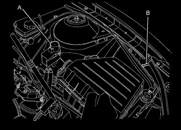
Lower Anchors
Lower anchors (A) are metal bars built into the vehicle. There are two lower anchors for each LATCH seating position that will accommodate a child restraint with lower attachments (B).
2-44
Seats and Restraints
Top Tether Anchor
A top tether (A, C) anchors the top of the child restraint to the vehicle. A top tether anchor is built into the vehicle. The top tether attachment (B) on the child restraint connects to the top tether anchor in the vehicle in order to reduce the forward movement and rotation of the child restraint during driving or in a crash.
Your child restraint may have a single tether (A) or a dual tether (C). Either will have a single attachment (B) to secure the top tether to the anchor. Some child restraints that have a top tether are designed for use with or without the top tether being attached. Others require the top tether always to be attached. In Canada, the law requires that forward-facing child restraints have a top tether, and that the tether be attached. Be sure to read and follow the instructions for your child restraint. If the child restraint does not have a top tether, one can be obtained, in kit form, for many child restraints. Ask the child restraint manufacturer whether or not a kit is available.
Lower Anchor and Top Tether Anchor Locations Rear Seat
i (Top Tether Anchor): Seating positions with top tether anchors.
j (Lower Anchor): Seating positions with two lower anchors.
Seats and Restraints
2-45
Do not secure a child restraint in a position without a top tether anchor if a national or local law requires that the top tether be attached, or if the instructions that come with the child restraint say that the top tether must be attached. According to accidents statistics, children and infants are safer when properly restrained in a child restraint system or infant restraint system secured in a rear seating position. See Where to Put the Restraint on page 2-41 for additional information.
To assist you in locating the lower anchors, each seating position with lower anchors has two labels, near the crease between the seatback and the seat cushion.
To assist you in locating the top tether anchors, the top tether anchor symbol is located on the cover of the anchor.
The top tether anchors are located on the rear seatback filler panel. Be sure to use an anchor located on the same side of the vehicle as the seating position where the child restraint will be placed.
2-46
Seats and Restraints
Securing a Child Restraint Designed for the LATCH System
{ WARNING
If a LATCH-type child restraint is not attached to anchors, the child restraint will not be able to protect the child correctly. In a crash, the child could be seriously injured or killed. Install a LATCH-type child restraint properly using the anchors, or use the vehicle’s safety belts to secure the restraint, following the instructions that came with the child restraint and the instructions in this manual.
{ WARNING
{ WARNING
Do not attach more than one child restraint to a single anchor. Attaching more than one child restraint to a single anchor could cause the anchor or attachment to come loose or even break during a crash. A child or others could be injured. To reduce the risk of serious or fatal injuries during a crash, attach only one child restraint per anchor.
Children can be seriously injured or strangled if a shoulder belt is wrapped around their neck and the safety belt continues to tighten. Buckle any unused safety belts behind the child restraint so children cannot reach them. Pull the shoulder belt all the way out of the retractor to set the lock, if your vehicle has one, after the child restraint has been installed.
Notice: Do not let the LATCH attachments rub against the vehicle’s safety belts. This may damage these parts. If necessary, move buckled safety belts to avoid rubbing the LATCH attachments.
Seats and Restraints
2-47
If the position you are using does not have a headrest or head restraint and you are using a dual tether, route the tether over the seatback.
3. Push and pull the child restraint in different directions to be sure it is secure.
2.
If the child restraint manufacturer recommends that the top tether be attached, attach and tighten the top tether to the top tether anchor, if equipped. Refer to the child restraint instructions and the following steps: 2.1. Find the top tether anchor. 2.2. Route, attach, and tighten
the top tether according to your child restraint instructions and the following instructions:
Do not fold the empty rear seat with a safety belt buckled. This could damage the safety belt or the seat. Unbuckle and return the safety belt to its stowed position, before folding the seat. 1. Attach and tighten the lower
attachments to the lower anchors. If the child restraint does not have lower attachments or the desired seating position does not have lower anchors, secure the child restraint with the top tether and the safety belts. Refer to your child restraint manufacturer instructions and the instructions in this manual. 1.1. Find the lower anchors for
the desired seating position.
1.2. Put the child restraint on
the seat.
1.3. Attach and tighten the lower
attachments on the child restraint to the lower anchors.
If the position you are using does not have a headrest or head restraint and you are using a single tether, route the tether over the seatback.
2-48
Seats and Restraints
Replacing LATCH System Parts After a Crash
{ WARNING
A crash can damage the LATCH system in the vehicle. A damaged LATCH system may not properly secure the child restraint, resulting in serious injury or even death in a crash. To help make sure the LATCH system is working properly after a crash, see your dealer/ retailer to have the system inspected and any necessary replacements made as soon as possible.
If the vehicle has the LATCH system and it was being used during a crash, new LATCH system parts may be needed. New parts and repairs may be necessary even if the LATCH system was not being used at the time of the crash.
Securing Child Restraints (Rear Seat) When securing a child restraint in a rear seating position, study the instructions that came with the child restraint to make sure it is compatible with this vehicle. If the child restraint has the LATCH system, see Lower Anchors and Tethers for Children (LATCH System) on page 2-43 for how and where to install your child restraint using LATCH. If a child restraint is secured in the vehicle using a safety belt and it uses a top tether, see Lower Anchors and Tethers for Children (LATCH System) on page 2-43 for top tether anchor locations. Do not secure a child restraint in a position without a top tether anchor if a national or local law requires that the top tether be anchored, or if the instructions that come with the child restraint say that the top strap must be anchored.
If the child restraint does not have the LATCH system, you will be using the safety belt to secure the child restraint in this position. Be sure to follow the instructions that came with the child restraint. Secure the child in the child restraint when and as the instructions say. If more than one child restraint needs to be installed in the rear seat, be sure to read Where to Put the Restraint on page 2-41. 1. Put the child restraint on
the seat.
2. Pick up the latch plate, and run the lap and shoulder portions of the vehicle’s safety belt through or around the restraint. The child restraint instructions will show you how.
Seats and Restraints
2-49
3. Push the latch plate into the
buckle until it clicks. Position the release button on the buckle so that the safety belt could be quickly unbuckled if necessary.
4. Pull the rest of the shoulder belt all the way out of the retractor to set the lock.
5. To tighten the belt, push down
on the child restraint, pull the shoulder portion of the belt to tighten the lap portion of the belt, and feed the shoulder belt back into the retractor. When installing a forward-facing child restraint, it may be helpful to use your knee to push down on the child restraint as you tighten the belt.
2-50
Seats and Restraints
6. If the child restraint has a top tether, follow the child restraint manufacturer’s instructions regarding the use of the top tether. See Lower Anchors and Tethers for Children (LATCH System) on page 2-43 for more information.
7. Push and pull the child restraint in different directions to be sure it is secure.
To remove the child restraint, unbuckle the vehicle safety belt and let it return to the stowed position. If the top tether is attached to a top tether anchor, disconnect it.
Securing Child Restraints (Right Front Seat) This vehicle has airbags. A rear seat is a safer place to secure a forward-facing child restraint. See Where to Put the Restraint on page 2-41
In addition, the vehicle has a passenger sensing system which is designed to turn off the right front passenger frontal airbag under certain conditions. See Passenger Sensing System on page 2-28 and Passenger Airbag Status Indicator on page 4-18 for more information, including important safety information. A label on the sun visor says, “Never put a rear-facing child seat in the front.” This is because the risk to the rear-facing child is so great, if the airbag deploys.{ WARNING
A child in a rear-facing child restraint can be seriously injured or killed if the right front passenger airbag inflates. This is because the back of the rear-facing child restraint would be very close to the inflating airbag. A child in a forward-facing child restraint can be seriously injured or killed if the right front passenger airbag inflates and the passenger seat is in a forward position. Even if the passenger sensing system has turned off the right front passenger frontal airbag, no system is fail-safe. No one can guarantee that an airbag will not deploy under some unusual circumstance, even though it is turned off.
(Continued)
WARNING (Continued)
Secure rear-facing child restraints in a rear seat, even if the airbag is off. If you secure a forward-facing child restraint in the right front seat, always move the front passenger seat as far back as it will go. It is better to secure the child restraint in a rear seat. See Passenger Sensing System on page 2-28 for additional information.
If the child restraint has the LATCH system, see Lower Anchors and Tethers for Children (LATCH System) on page 2-43 for how and
where to install the child restraint using LATCH. If a child restraint is secured using a safety belt and it uses a top tether, see Lower Anchors and Tethers for Children (LATCH System) on page 2-43 for top tether anchor locations. Do not secure a child seat in a position without a top tether anchor if a national or local law requires that the top tether be anchored, or if the instructions that come with the child restraint say that the top strap must be anchored. In Canada, the law requires that forward-facing child restraints have a top tether, and that the tether be attached.
Seats and Restraints
2-51
You will be using the lap-shoulder belt to secure the child restraint in this position. Follow the instructions that came with the child restraint. 1. Move the seat as far back as it will go before securing the forward-facing child restraint. When the passenger sensing system has turned off the right front passenger frontal airbag, the off indicator on the passenger airbag status indicator should light and stay lit when the vehicle is started. See Passenger Airbag Status Indicator on page 4-18. 2. Put the child restraint on
the seat. If the seat has a safety belt guide, remove the safety belt from the guide by unsnapping the guide on the seat. Do not secure the child restraint with the safety belt routed through the guide.
2-52
Seats and Restraints
3. Pick up the latch plate, and run
the lap and shoulder portions of the vehicle’s safety belt through or around the restraint. The child restraint instructions will show you how.
5. Pull the rest of the shoulder belt all the way out of the retractor to set the lock.
6. To tighten the belt, push down
on the child restraint, pull the shoulder portion of the belt to tighten the lap portion of the belt and feed the shoulder belt back into the retractor. When installing a forward-facing child restraint, it may be helpful to use your knee to push down on the child restraint as you tighten the belt. 7. Push and pull the child restraint in different directions to be sure it is secure.
4. Push the latch plate into the
buckle until it clicks. Position the release button on the buckle, so that the safety belt could be quickly unbuckled if necessary.
Seats and Restraints
2-53
If the airbag is off, the off indicator in the passenger airbag status indicator will come on and stay on when the vehicle is started. If a child restraint has been installed and the on indicator is lit, see “If the On Indicator is Lit for a Child Restraint” under Passenger Sensing System on page 2-28 for more information. To remove the child restraint, unbuckle the vehicle safety belt and let it return to the stowed position. If the seat has a safety belt guide, return the safety belt into the guide by snapping the guide around the webbing.
2-54
Seats and Restraints
✍ NOTES
Storage
Storage Compartments Glove Box ............................3-1
Center Console Storage .........3-1
Additional Storage Features Convenience Net ...................3-1Storage Compartments Glove Box Open the glove box by lifting up on the lever. Use the key to lock and unlock the glove box.
Center Console Storage To open, lift the latch on the front edge. There is an Accessory Power Outlet (APO) and an optional USB/audio jack located in the storage area. See Power Outlets on page 4-9
and Auxiliary Devices on page 6-16
for more information.Storage
3-1
Additional Storage Features Convenience Net For vehicles with a convenience net located inside the trunk, it can be used to secure loose items.
The upper (A) and lower (C) hooks on each side of the trunk opening are provided to attach the net. Install the opening of the net at the top and over the two middle hooks (B).
3-2
Storage
✍ NOTES
Instruments and Controls
Instrument Panel Overview Instrument Panel Overview ......4-4
Controls Steering Wheel Adjustment .....4-6
Steering Wheel Controls .........4-6
Horn ....................................4-7
Windshield Wiper/Washer .......4-7
Compass .............................4-8
Clock ...................................4-8
Power Outlets .......................4-9
Warning Lights, Gages, and Indicators Warning Lights, Gages, and Indicators .....................4-9
Instrument Cluster ...............4-10
Speedometer ......................4-11
Odometer ...........................4-11
Trip Odometer .....................4-11
Tachometer ........................4-11
Fuel Gage ..........................4-11
Engine Oil Pressure Gage ......4-12Instruments and Controls
4-1
Engine Oil Temperature Gage .............4-13
Engine Coolant Temperature Gage .............4-14
Transmission Temperature Gage .............4-14
Voltmeter Gage ...................4-15
Safety Belt Reminders ..........4-16
Airbag Readiness Light .........4-17
Passenger Airbag Status Indicator ...........................4-18
Charging System Light .........4-19
Malfunction Indicator Lamp ..................4-19
Brake System Warning Light ................................4-22
Antilock Brake System (ABS) Warning Light ...........4-23
Traction Off Light .................4-23
Traction Control System (TCS)/StabiliTrak® Light .......4-24
Traction Control System (TCS) OFF/StabiliTrak® OFF Light ................................4-24
Tire Pressure Light ..............4-24
Engine Oil Pressure Light .....4-25
Immobilizer Light .................4-26
Fog Lamp Light ...................4-26
Taillamp Indicator Light .........4-26
Cruise Control Light .............4-26Information Displays Driver Information Center (DIC) .....................4-27
Vehicle Messages Battery Voltage and Charging Messages ............4-30
Brake System Messages ......4-31
Compass Messages .............4-31
Cruise Control Messages ......4-31
Door Ajar Messages ............4-31
Engine Cooling System Messages .........................4-32
Engine Oil Messages ...........4-32
Engine Power Messages ......4-33
Fuel System Messages ........4-33
Key and Lock Messages ......4-33
Lamp Messages ..................4-33
Object Detection System Messages .........................4-34
Ride Control System Messages .........................4-34
Airbag System Messages ......4-35
Safety Belt Messages ...........4-35
Anti-Theft Alarm System Messages .........................4-35
Service Vehicle Messages .....4-35
Tire Messages ....................4-36
Transmission Messages ........4-36
Vehicle Reminder Messages .........................4-374-2
Instruments and Controls
Vehicle Speed Messages ......4-37
Vehicle Messages ................4-37
Window Messages ...............4-37
Vehicle Personalization Vehicle Personalization .........4-38
OnStar System OnStar® System ..................4-42
Universal Remote System Universal Remote System .....4-45
Universal Remote System Programming .....................4-45
Universal Remote System Operation ..........................4-48Instruments and Controls
4-3
✍ NOTES
4-4
Instruments and Controls
Instrument Panel Overview
A. Air Vents on page 7-3. B. Driver Shift Controls
(If Equipped). See Automatic Transmission on page 8-26. Instrument Cluster on page 4-10.
C. D. Windshield Wiper/Washer on
page 4-7.
E. AM-FM Radio on page 6-8. F. Turn and Lane-Change Signals
on page 5-4. Headlamp High/Low-Beam Changer on page 5-2. Flash-to-Pass on page 5-3. Driver Information Center (DIC) on page 4-27
(If Equipped).Instruments and Controls
4-5
G. Cruise Control on page 8-38. H. Exterior Lamp Controls on page 5-1. Front Fog Lamps on page 5-5 (If Equipped). Instrument Panel Illumination Control on page 5-5.
I. Steering Wheel Adjustment on
page 4-6.
J. Horn on page 4-7. K. Steering Wheel Controls on
page 4-6.
L. Climate Control Systems on
page 7-1.
M. Transmission Temperature
Gage on page 4-14. Voltmeter Gage on page 4-15. Engine Oil Temperature Gage on page 4-13. Engine Oil Pressure Gage on page 4-12.
N. Shift Lever. See Shifting Into
Park on page 8-21.
O. Power Outlets on page 4-9. P. Hazard Warning Flashers on page 5-4. Power Door Locks on page 1-7.
Q. Glove Box on page 3-1.
4-6
Instruments and Controls
Controls Steering Wheel Adjustment A tilt and telescope wheel lets the steering wheel be adjusted.
backward or forward into a comfortable position. Pull the lever up to lock the steering wheel in place. Do not adjust the tilt lever while driving.
Steering Wheel Controls
The lever is on the outboard side of the steering column.
To adjust the steering wheel, pull the lever down. Then move the steering wheel up or down or
For vehicles with audio steering wheel controls, some audio controls can be adjusted at the steering wheel.
b / g (Push to Talk): For vehicles with OnStar® or Bluetooth® systems, press to interact with those systems. See OnStar® System on page 4-42 and Bluetooth (Overview) on page 6-22 or Bluetooth (Infotainment Controls) on page 6-23 or Bluetooth (Voice Recognition) on page 6-26
for more information.c / $ (End Call / Mute): Press to reject an incoming call, or end a current call. Press to silence the vehicle speakers while using the infotainment system. Press again to turn the sound on.
_ SRC ^ (Toggle Switch): Press to select an audio source.
Toggle up or down to select the next or previous favorite radio station or CD/MP3 track. + x − (Volume): Press + or − to increase or decrease the volume.
Instruments and Controls
4-7
Horn Press near or on the horn symbols on the steering wheel pad to sound the horn.
Windshield Wiper/Washer The windshield wiper/washer lever is located on the inboard side of the steering column.
9 (Off): Turns the wipers off. 6 (Intermittent): Move the lever to choose a delayed wiping cycle.
For vehicles with the variable intermittent feature, the time between wipes can be adjusted. Turn the & band for a longer or shorter delay interval.
x (Low): Slow wipes.
[ (High): Fast wipes.
Windshield Washer: Pull the lever toward you to spray washer fluid on the windshield. The spray continues until the lever is released. The wipers will run a few times. See Washer Fluid on page 9-26 for information on filling the windshield washer fluid reservoir.
Push up or pull down on the lever to place it in one of the following positions. 8 (Mist): For a single wiping cycle. The lever returns to its starting position when released. For more cycles, hold the lever down before releasing it.
{ WARNING
In freezing weather, do not use your washer until the windshield is warmed. Otherwise the washer fluid can form ice on the windshield, blocking your vision.
Clear ice and snow from the wiper blades before using them. If the wiper blades are frozen to the windshield, gently loosen or thaw them. If they become damaged, install new blades or blade inserts. See Wiper Blade Replacement on page 9-33. Heavy snow or ice can overload the wiper motor. A circuit breaker will stop the motor until it cools down.
4-8
Instruments and Controls
Compass The vehicle may have a compass display on the Driver Information Center (DIC). The compass is an OnStar compass and receives its heading and other information from OnStar. See OnStar® System on page 4-42 for more information about the OnStar system.
Clock The infotainment system controls are used to access the time and date settings through the menu system. See Operation on page 6-4 for information about how to use the menu system.
Setting the Time and Date 1. Press the CONFIG button. 2. Select Time and Date Settings. 3. Select Set Time or Set Date. 4. Turn the MENU/SELECT knob to
adjust the highlighted value.
5. Press the MENU/SELECT knob
to select the next value.
6. To save the time or date and return to the Time and Date Settings menu, press the 0 BACK button at any time or press MENU/SELECT knob after adjusting the minutes or year.
Setting the 12/24 Hour Format 1. Press the CONFIG button. 2. Select Time and Date Settings. 3. Highlight 12/24 Hour Format. 4. Press the MENU/SELECT knob to select the 12 hour or 24 hour display format.
Setting the Month & Day Format 1. Press the CONFIG button. 2. Select Time and Date Settings. 3. Highlight Month & Day Format. 4. Press the MENU/SELECT knob to select MM/DD (month/day) or DD/MM (day/month).
Setting the Auto Time Adjust 1. Press the CONFIG button. 2. Select Time and Date Settings. 3. Highlight Auto Time Adjust. 4. Press the MENU/SELECT knob
to turn Auto Time Adjust on or off.
Power Outlets The vehicle has two accessory power outlets; one is located below the climate control system and the other is inside the center storage console. The accessory power outlets do not work when the key is removed from the ignition and the driver door is opened, this helps to preserve the battery life of the vehicle. Certain power accessory plugs may not be compatible to the accessory power outlet and could result in blown vehicle or adapter fuses. If you experience a problem, see your dealer/retailer for additional information on the accessory power plugs.
Instruments and Controls
4-9
Notice: Adding any electrical equipment to the vehicle can damage it or keep other components from working as they should. The repairs would not be covered by the vehicle warranty. Each outlet is rated to a maximum output of 120W. Usage of equipment exceeding an amperage rating of 20A may require fuse replacement. Check with your dealer/retailer before adding electrical equipment. When adding electrical equipment, be sure to follow the proper installation instructions included with the equipment. Notice: power outlet can cause damage not covered by the warranty. Do not hang any type of accessory or accessory bracket from the plug because the power outlets are designed for accessory power plugs only.
Improper use of the
Warning Lights, Gages, and Indicators Warning lights come on when there could be a problem with a vehicle function. Some warning lights come on briefly when the engine is started to indicate they are working. Gages can indicate when there could be a problem with a vehicle function. Often gages and warning lights work together to indicate a problem with the vehicle. When one of the warning lights comes on and stays on while driving, or when one of the gages shows there may be a problem, check the section that explains what to do. Follow this manual’s advice. Waiting to do repairs can be costly and even dangerous.
4-10
Instruments and Controls
Instrument Cluster
United States Uplevel Automatic Transmission Shown, Canada and Manual Transmission similar
Speedometer The speedometer shows the vehicle’s speed in both kilometers per hour (km/h) and miles per hour (mph).
Odometer The odometer shows how far the vehicle has been driven, in either kilometers or miles. This vehicle has a tamper-resistant odometer. If the vehicle needs a new odometer installed, the new one is set to the mileage of the old odometer. If this is not possible, it is set at zero and a label is put on the driver’s door to show the old mileage reading.
Trip Odometer The trip odometer shows how far the vehicle has been driven since the trip odometer was last set to zero. Set the odometer using the Driver Information Center (DIC).
Instruments and Controls
4-11
To set the trip odometer to zero, press and hold the SET button while the trip odometer display is showing.
Tachometer The tachometer displays the engine speed in revolutions per minute (rpm).
Fuel Gage
Canada
When the ignition is on, the fuel gage shows about how much fuel the vehicle has left in the fuel tank. An arrow on the fuel gage indicates which side of the vehicle the fuel door is located. The gage indicates empty before the vehicle is out of fuel, to show that the vehicle’s fuel tank should be filled soon.
United States
4-12
Instruments and Controls
When the fuel tank is low on fuel, a Fuel Level Low message will appear on the Driver Information Center (DIC). For more information see Fuel System Messages on page 4-33. Here are some situations that can occur with the fuel gage. None of these indicate a problem with the fuel gage. • At the gas station, the fuel pump
•
shuts off before the gage reads full. It takes a little more or less fuel to fill up than the fuel gage indicated. For example, the gage may have indicated the tank was half full, but it actually took a little more or less than half the tank’s capacity to fill the tank.
• The pointer on the fuel gage is on
empty when the ignition is off.
Engine Oil Pressure Gage
United States
Canada
The oil pressure gage, located in front of the shifter, shows the engine oil pressure in psi (pounds per square inch) when the engine is running. Canadian vehicles indicate pressure in kPa (kilopascals). Oil pressure may vary with engine speed, outside temperature and oil viscosity, but readings above the low pressure zone indicate the normal operating range. When the oil pressure reaches the low pressure zone, a message appears in the Driver Information Center (DIC).
See Engine Oil Messages on page 4-32 and Engine Oil on page 9-10 for more information.
Engine Oil Temperature Gage
Instruments and Controls
4-13
{ WARNING
Do not keep driving if the oil pressure is low. The engine can become so hot that it catches fire. Someone could be burned. Check the oil as soon as possible and have the vehicle serviced.
Notice: Lack of proper engine oil maintenance can damage the engine. The repairs would not be covered by the vehicle warranty. Always follow the maintenance schedule in this manual for changing engine oil. A reading in the low pressure zone can be caused by a dangerously low oil level or some other problem causing low oil pressure. Check the oil as soon as possible.
United States
Canada
This gage, located in front of the shifter, shows the engine oil temperature. If the gage pointer moves into the red area, it means that the engine oil has overheated. If the vehicle has been operated under normal driving conditions, pull off the road, stop the vehicle and turn off the engine as soon as possible. See Engine Oil on page 9-10 for more information.
4-14
Instruments and Controls
Engine Coolant Temperature Gage
Transmission Temperature Gage
United States
Canada
This gage shows the engine coolant temperature. If the gage pointer moves towards the H, the engine is too hot. This reading indicates the same thing as the warning message. It means that the engine coolant has overheated. If the vehicle has been operating under normal driving conditions, pull off the road, stop the vehicle, and turn off the engine as soon as possible. See Engine Overheating on page 9-24 for more information.
United States
Instruments and Controls
4-15
If the vehicle is driven
For information on the DIC messages see Transmission Messages on page 4-36. Notice: with the transmission temperature gage above the normal operating range, the transmission can be damaged. This could lead to costly repairs that would not be covered by the vehicle warranty. Do not drive the vehicle while the transmission temperature gage reading is above normal. See your dealer/retailer for service.
Voltmeter Gage
United States Version Shown,
Canada Similar
This gage, located in front of the shifter, shows the battery’s state of charge in DC volts. When the engine is running, but the ignition is on, this gage shows the condition of the charging system. The vehicle’s charging system regulates voltage based on the state of charge of the battery. It is normal for the voltmeter to fluctuate.
Canada
This gage, located in front of the shifter, shows the transmission oil temperature when the ignition is on. If the gage is reading in the red area and/or a message appears in the DIC, the vehicle must be stopped and the cause checked. One possible cause is a low level in the transmission.
4-16
Instruments and Controls
Readings between the low and high warning zones indicate the normal operating range. Readings in the low warning zone can occur when a large number of electrical accessories are operating in the vehicle and the engine is left idling for an extended period. If there is a problem with the battery charging system, a message appears in the Driver Information Center (DIC) and/or the charging system light comes on. See Battery Voltage and Charging Messages on page 4-30 and Charging System Light on page 4-19 for more information. However, readings in either warning zone can indicate a possible problem in the electrical system. Have the vehicle serviced as soon as possible.
Safety Belt Reminders Driver Safety Belt Reminder Light There is a driver safety belt reminder light on the instrument panel cluster.
Passenger Safety Belt Reminder Light
The passenger safety belt reminder light is located on the overhead console. When the engine is started, this light and the chime come on and stay on for several seconds to remind the passenger to fasten their safety belt. The light also begins to flash. This cycle repeats if the passenger remains unbuckled and the vehicle is moving.
When the engine is started this light and a chime come on and stay on for several seconds to remind drivers to fasten their safety belts. The light also begins to flash. This cycle repeats if the driver remains unbuckled and the vehicle is moving. If the driver safety belt is already buckled, neither the light nor chime come on.
Instruments and Controls
4-17
If the passenger safety belt is buckled, neither the chime nor the light comes on. The front passenger safety belt warning light and chime may turn on if an object is put on the seat such as a briefcase, handbag, grocery bag, laptop or other electronic device. To turn off the warning light and or chime, remove the object from the seat or buckle the safety belt
Airbag Readiness Light This light shows if there is an electrical problem. The system check includes the airbag sensor, the pretensioners, the airbag modules, the wiring and the crash sensing and diagnostic module.
For more information on the airbag system, see Airbag System on page 2-21.
The airbag readiness light comes on and stays on for several seconds when the vehicle is started. Then the light goes out. If it stays on after the vehicle has been started or comes on while driving, the airbag system may not work properly. Have the vehicle serviced right away.
{ WARNING
If the airbag readiness light stays on after the vehicle is started or comes on while driving, it means the airbag system might not be working properly. The airbags in the vehicle might not inflate in a crash, or they could even inflate without a crash. To help avoid injury, have the vehicle serviced right away.
4-18
Instruments and Controls
Passenger Airbag Status Indicator The vehicle has a passenger sensing system. See Passenger Sensing System on page 2-28
for important safety information. The overhead console has a passenger airbag status indicator.United States
Canada
When the vehicle is started, the passenger airbag status indicator will light ON and OFF, or the symbol for on and off, for several seconds as a system check. If you are using remote start to start your vehicle from a distance, if equipped, you may not see the system check. Then, after several seconds, the status indicator will light either ON or OFF, or either the on or off symbol to let you know the status of the right front passenger frontal airbag. If the word ON or the on symbol is lit on the passenger airbag status indicator, it means that the right front passenger frontal airbag is enabled (may inflate).
If the word OFF or the off symbol is lit on the passenger airbag status indicator, it means that the passenger sensing system has turned off the right front passenger frontal airbag. If, after several seconds, both status indicator lights remain on, or if there are no lights at all, there may be a problem with the lights or the passenger sensing system. See your dealer/retailer for service.
{ WARNING
If the airbag readiness light ever comes on and stays on, it means that something may be wrong with the airbag system. To help avoid injury to yourself or others, have the vehicle serviced right away. See Airbag Readiness Light on page 4-17 for more information, including important safety information.
Charging System Light
The charging system light comes on briefly when the ignition is turned on but the engine is not running, as a check to show the light is working. It should go out when the engine is started. If the light stays on, or comes on while driving, there may be a problem with the electrical charging system. Have it checked by your dealer/retailer. Driving while this light is on could drain the battery. When this light comes on, the Driver Information Center (DIC) also displays a message. See Battery Voltage and Charging Messages on page 4-30.
Instruments and Controls
4-19
If a short distance must be driven with the light on, be sure to turn off all accessories, such as the radio and air conditioner.
Malfunction Indicator Lamp Check Engine Light A computer system called OBD II (On-Board Diagnostics-Second Generation) monitors operation of the fuel, ignition, and emission control systems. It ensures that emissions are at acceptable levels for the life of the vehicle, helping to produce a cleaner environment.
This light comes on when the ignition is on, but the engine is not running, as a check to show it
is working. If it does not, have the vehicle serviced by your dealer/retailer. If the check engine light comes on and stays on, while the engine is running, this indicates that there is an OBD II problem and service is required. Malfunctions often are indicated by the system before any problem is apparent. Being aware of the light can prevent more serious damage to the vehicle. This system assists the service technician in correctly diagnosing any malfunction. Notice: continually driven with this light on, after a while, the emission controls might not work as well, the vehicle’s fuel economy might not be as good, and the engine might not run as smoothly. This could lead to costly repairs that might not be covered by the vehicle warranty.
If the vehicle is
4-20
Instruments and Controls
Notice: Modifications made to the engine, transmission, exhaust, intake, or fuel system of the vehicle or the replacement of the original tires with other than those of the same Tire Performance Criteria (TPC) can affect the vehicle’s emission controls and can cause this light to come on. Modifications to these systems could lead to costly repairs not covered by the vehicle warranty. This could also result in a failure to pass a required Emission Inspection/Maintenance test. See Accessories and Modifications on page 9-3.
This light comes on during a malfunction in one of two ways: Light Flashing: A misfire condition has been detected. A misfire increases vehicle emissions and could damage the emission control system on the vehicle. Diagnosis and service might be required.
The following can prevent more serious damage to the vehicle: • Reduce vehicle speed. • Avoid hard accelerations. • Avoid steep uphill grades. If the light continues to flash, when it is safe to do so, stop the vehicle. Find a safe place to park the vehicle. Turn the engine off, wait at least 10 seconds, and restart the engine. If the light is still flashing, follow the previous steps and see your dealer/retailer for service as soon as possible.
Light On Steady: An emission control system malfunction has been detected on the vehicle. Diagnosis and service might be required. An emission system malfunction might be corrected by: • Make sure the fuel cap is fully installed. See Filling the Tank on page 8-46. The diagnostic system can determine if the fuel cap has been left off or improperly installed. A loose or missing fuel cap allows fuel to evaporate into the atmosphere. A few driving trips with the cap properly installed should turn the light off. If the vehicle has been driven through a deep puddle of water, the vehicle’s electrical system might be wet. The condition is usually corrected when the electrical system dries out. A few driving trips should turn the light off.
•
Instruments and Controls
4-21
inspection. This can happen if the battery has recently been replaced or if the battery has run down. The diagnostic system is designed to evaluate critical emission control systems during normal driving. This can take several days of routine driving. If this has been done and the vehicle still does not pass the inspection for lack of OBD II system readiness, your dealer/retailer can prepare the vehicle for inspection.
• Make sure to fuel the vehicle with
quality fuel. Poor fuel quality causes the engine not to run as efficiently as designed and can cause: stalling after start-up, stalling when the vehicle is changed into gear, misfiring, hesitation on acceleration, or stumbling on acceleration. These conditions might go away once the engine is warmed up. If one or more of these conditions occurs, change the fuel brand used. It will require at least one full tank of the proper fuel to turn the light off. See Gasoline Specifications on page 8-44.
If none of the above have made the light turn off, your dealer/retailer can check the vehicle. The dealer/retailer has the proper test equipment and diagnostic tools to fix any mechanical or electrical problems that might have developed.
Emissions Inspection and Maintenance Programs Some state/provincial and local governments have or might begin programs to inspect the emission control equipment on the vehicle. Failure to pass this inspection could prevent getting a vehicle registration. Here are some things to know to help the vehicle pass an inspection: • The vehicle will not pass this inspection if the check engine light is on with the engine running, or if the key is in ON/RUN and the light is not on.
• The vehicle will not pass
this inspection if the OBD II (on-board diagnostic) system determines that critical emission control systems have not been completely diagnosed by the system. The vehicle would be considered not ready for
4-22
Instruments and Controls
When the ignition is on, the brake system warning light also comes on when parking brake is set. The light stays on if the parking brake does not fully release. If it stays on after the parking brake is fully released, it means the vehicle has a brake problem. If, while driving, the light comes on and a brake message comes on the Driver Information Center (DIC), pull off the road and stop carefully. The pedal could be harder to push or the pedal can go closer to the floor. It could take longer to stop. If the light is still on, have the vehicle towed for service. See Antilock Brake System (ABS) Warning Light on page 4-23
and Driving Characteristics and Towing Tips on page 8-49.{ WARNING
The brake system might not be working properly if the brake system warning light is on. Driving with the brake system warning light on can lead to a crash. If the light is still on after the vehicle has been pulled off the road and carefully stopped, have the vehicle towed for service.
The Brake message remains on until the menu button is pressed. The brake light remains until the problem is fixed. See Brake System Messages on page 4-31
for more information.Brake System Warning Light The vehicle’s hydraulic brake system is divided into two parts. If one part is not working, the other part can still work and stop the vehicle. For good braking both parts need to work well. If the warning light comes on, there is a brake problem. Have the brake system inspected right away.
United States
Canada
If the vehicle has antilock brakes, this light should come on when the key is turned to START. If it does not come on, have it fixed so it will be ready to warn if there is a problem.
Instruments and Controls
4-23
Antilock Brake System (ABS) Warning Light
The Antilock Brake System (ABS) light comes on briefly when the engine is started. If the light does not come on, have it fixed so it will be ready to warn if there is a problem. If the ABS light stays on, turn the ignition off. If the light comes on while driving, stop as soon as it is safely possible and turn the ignition off. Then start the engine again to reset the system.
If the ABS light stays on, or comes on again while driving, the vehicle needs service. A chime may also sound when the light comes on steady. If the ABS light is the only light on, the vehicle has regular brakes, but the antilock brakes are not functioning. If both lights are on, the vehicle’s antilock brakes are not functioning and there is a problem with the regular brakes. See your dealer/retailer for service. See Brake System Warning Light on page 4-22. See Brake System Messages on page 4-31 for all brake related DIC messages.
Traction Off Light
This light comes on when the Traction Control System (TCS) has been turned off by pressing and releasing the traction control button. This light also comes on and the system turns off if the there is a problem with the TCS. If the light comes on and stays on for an extended period of time while the system is turned on, the vehicle needs service. See Traction Control System (TCS) on page 8-34 and StabiliTrak System on page 8-36 for more information.
4-24
Instruments and Controls
Traction Control System (TCS)/StabiliTrak® Light
The StabiliTrak system or the Traction Control System (TCS) indicator/warning light comes on briefly while starting the engine. If it does not, have the vehicle serviced by your dealer/retailer. If the system is working normally the indicator light will then go off. The indicator/warning light flashes while the StabiliTrak or TCS system is working to control the vehicle on a low traction surface. If the TCS indicator/warning light comes on and stays on while driving, the vehicle needs service.
See Competitive Driving Mode on page 8-37, Traction Control System (TCS) on page 8-34 and StabiliTrak System on page 8-36 for more information
Traction Control System (TCS) OFF/StabiliTrak® OFF Light
For SS models, if this light is on, the vehicle is in Competitive Mode. A warning also appears in the DIC for StabiliTrak Competitive Mode. See Ride Control System Messages on page 4-34 for more information. See Traction Control System (TCS) on page 8-34 and StabiliTrak System on page 8-36 for more information
Tire Pressure Light
This light comes on when the StabiliTrak system is turned off. If the Traction Control System (TCS) is off, wheel spin is not limited. If the StabiliTrak system is off, the system does not assist in controlling the vehicle. Turn on the TCS and the StabiliTrak system and the warning light turns off.
For vehicles with a tire pressure light, this light comes on briefly when the engine is started and provides information about tire pressures and the Tire Pressure Monitoring System.
Instruments and Controls
4-25
Engine Oil Pressure Light
{ WARNING
Do not keep driving if the oil pressure is low. The engine can become so hot that it catches fire. Someone could be burned. Check the oil as soon as possible and have the vehicle serviced.
Notice: Lack of proper engine oil maintenance can damage the engine. The repairs would not be covered by the vehicle warranty. Always follow the maintenance schedule in this manual for changing engine oil.
When the Light is On Steady This indicates that one or more of the tires are significantly underinflated. A tire pressure message in the Driver Information Center (DIC), can accompany the light. See Tire Messages on page 4-36 for more information. Stop and check the tires as soon as it is safe to do so. If underinflated, inflate to the proper pressure. See Tire Pressure on page 9-54 for more information. When the Light Flashes First and Then is On Steady This indicates that there may be a problem with the Tire Pressure Monitor System. The light flashes for about a minute and stays on steady for the remainder of the ignition cycle. This sequence repeats with every ignition cycle. See Tire Pressure Monitor Operation on page 9-57 for more information.
The oil pressure light should come on briefly as the engine is started. If it does not come on have the vehicle serviced by your dealer/retailer. If the light comes on and stays on, it means that oil is not flowing through the engine properly. The vehicle could be low on oil and might have some other system problem. See your dealer/retailer.
4-26
Instruments and Controls
Immobilizer Light
Fog Lamp Light
Cruise Control Light
The immobilizer light should come on briefly as the engine is started. If it does not come on have the vehicle serviced by your dealer/ retailer. If the system is working normally the indicator light will go off. This light comes on when the ignition is turned from OFF to ON and stays on if the vehicle is immobilized. This happens when an incorrect key or an unprogrammed key is used to start the vehicle. If the light stays on and the engine does not start, there could be a problem with the theft-deterrent system. See Immobilizer Operation on page 1-11 for more information.
The fog lamp light comes on when the fog lamps are in use. The light goes out when the fog lamps are turned off. See Front Fog Lamps on page 5-5 for more information.
Taillamp Indicator Light
This light is white when the cruise control is set and will be green when the system is active. The light goes out when the cruise control is turned off. See Cruise Control on page 8-38 for more information.
This light comes on when the taillamps are on.
Instruments and Controls
4-27
Information Displays Driver Information Center (DIC) The vehicle may have a Driver Information Center (DIC). The DIC displays information about your vehicle. It also displays warning messages if a system problem is detected. See Vehicle Messages on page 4-37 for more information. All messages appear in the DIC display located in the center of the instrument panel cluster. The vehicle may also have features that can be customized through the controls on the radio. See Vehicle Personalization on page 4-38
for more information.DIC Operation and Displays The DIC has different displays which can be accessed by using the DIC buttons located on the turn signal lever located on the left side of the steering wheel. The DIC displays trip, fuel, vehicle system information, and warning messages if a system problem is detected. The bottom of the DIC display shows what position the shift lever is in (Automatic Transmission Only), the odometer, and the direction the vehicle is driving.
DIC Buttons
MENU: Press this button to get to the Trip/Fuel Menu and the Vehicle Information Menu. w x (Thumbwheel): Use the thumbwheel to scroll through the items in each menu. SET (Set/Clear): Use this button to set or clear the menu item when it is displayed.
4-28
Instruments and Controls
Trip/Fuel Menu Items Press the MENU button on the turn signal lever until Trip/Fuel Information Menu is displayed. Use the thumbwheel to scroll through the following menu items: • Digital Speedometer • Trip 1
• Trip 2
• Fuel Range • Average Fuel Economy • Average Vehicle Speed • OnStar Turn by Turn • BlankDigital Speedometer The speedometer shows how fast the vehicle is moving in either miles per hour (mph) or kilometers per hour (km/h). The speedometer cannot be reset.
Trip 1 and Trip 2
The Trip display shows the current distance traveled, in either miles (mi) or kilometers (km), since the last reset for the trip odometer. The trip odometer can be reset to zero by pressing the trip reset stem or the SET button while the trip odometer display is showing.Fuel Range The Fuel Range display shows the approximate distance the vehicle can be driven without refueling. The fuel range estimate is based on an average of the vehicle’s fuel economy over recent driving history and the amount of fuel remaining in the fuel tank. Fuel range cannot be reset.
Average Fuel Economy The Average Fuel Economy display shows the approximate average miles per gallon (mpg) or liters per 100 kilometers (L/100 km). This number is calculated based on the number of mpg (L/100 km) recorded since the last time this menu item was reset. The fuel economy can be reset by pressing the SET button while the Average Fuel Economy display is showing.
Average Vehicle Speed The Average Vehicle Speed display shows the average speed of the vehicle in miles per hour (mph) or kilometers per hour (km/h). This average is calculated based on the various vehicle speeds recorded since the last reset of this value. The average speed can be reset by pressing the SET button while the Average Vehicle Speed display is showing.
OnStar Turn by Turn This display is used for the OnStar Turn by Turn guidance. See OnStar® System on page 4-42 for more information. Blank Display This display shows no information.
Vehicle Information Menu Items Press the MENU button on the turn signal lever until Vehicle Information Menu is displayed. Use the thumbwheel to scroll through the following menu items: • Unit • Tire Pressure • Remaining Oil Life • Coolant Temp • Battery Voltage • Speed Warning
Instruments and Controls
4-29
Unit Move the thumbwheel up or down to switch between US or Metric when the Unit display is active. Press SET to confirm the setting. This will change the displays on the cluster and DIC to either English (US) or metric measurements.
Tire Pressure The display will show a vehicle with the approximate pressures of all four tires. Tire pressure is displayed in either pounds per square inch (psi) or in kilopascal (kPa). See Tire Pressure Monitor System on page 9-56 and Tire Pressure Monitor Operation on page 9-57
for more information.Remaining Oil Life This display shows an estimate of the oil’s remaining useful life. If Remaining Oil Life 99% is displayed, that means 99% of the current oil life remains.
When the remaining oil life is low, the CHANGE ENGINE OIL SOON message will appear on the display. See Engine Oil Messages on page 4-32. The oil should changed as soon as possible. See Engine Oil on page 9-10. In addition to the engine oil life system monitoring the oil life, additional maintenance is recommended in the Maintenance Schedule in this manual. See Scheduled Maintenance on page 10-2 for more information. Remember, the Oil Life display must be reset after each oil change. It will not reset itself. Also, be careful not to reset the Oil Life display accidentally at any time other than when the oil has just been changed. It cannot be reset accurately until the next oil change. To reset the engine oil life system press the SET button while the Oil Life display is active. See Engine Oil Life System on page 9-13.
4-30
Instruments and Controls
Coolant Temperature This display shows the temperature of the engine cooling system fluid in either degrees Fahrenheit (°F) or degrees Celsius (°C).
Battery Voltage This display, available on some vehicles, shows the current battery voltage. If the voltage is in the normal range, the value will display. For example, the display may read Battery Voltage 15.0 Volts. The vehicle’s charging system regulates voltage based on the state of the battery. The battery voltage can fluctuate while viewing this information on the DIC. This is normal. See Charging System Light on page 4-19
for more information.If there is a problem with the battery charging system, the DIC will display a message. See Battery Voltage and Charging Messages on page 4-30.
Vehicle Messages Battery Voltage and Charging Messages
Speed Warning Speed Warning allows the driver to set a speed that they do not want to exceed. To set the Speed Warning press SET when Speed Warning is displayed.
Compass The vehicle may have a compass display in the Driver Information Center (DIC). See Compass on page 4-8 for more information.
Battery Saver Active This message displays when the vehicle has detected that the battery voltage is dropping beyond a reasonable point. The battery saver system starts reducing certain features of the vehicle that you may be able to notice. At the point that features are disabled, this message is displayed. It means that the vehicle is trying to save the charge in the battery. Turn off unnecessary accessories to allow the battery to recharge.
Instruments and Controls
4-31
Compass Messages Service Compass This message is displayed when the compass needs service. Take the vehicle to your dealer/retailer for service.
Cruise Control Messages Apply Brakes Before Cruise If this message displays when attempting to activate cruise control, apply the brake and then try again.
Cruise Set to XXX This message will display when the cruise control is set and it will show the speed it was set to. See Cruise Control on page 8-38
for more information.Door Ajar Messages Driver Door Open This message will display when the driver door is open. Close the door completely.
Hood Open This message will display when the hood is open. Close the hood completely.
Passenger Door Open This message will display when the passenger door is open. Close the door completely.
Trunk Open This message will display when the trunk is open. Close the trunk completely.
Low Battery This message is displayed when the battery voltage is low. See Battery on page 9-29 for more information. Service Battery Charging System This message is displayed when there is a fault in the battery charging system. Take the vehicle to your dealer/retailer for service.
Brake System Messages Brake Fluid Low This message is displayed when the brake fluid level is low, see Brake Fluid on page 9-28.
Release Parking Brake This message is displayed as a reminder that the parking brake is on. Release it before you attempt to drive.
4-32
Instruments and Controls
Engine Cooling System Messages A/C Off Due to High Engine Temp This message displays when the engine coolant becomes hotter than the normal operating temperature. To avoid added strain on a hot engine, the air conditioning compressor automatically turns off. When the coolant temperature returns to normal, the air conditioning compressor turns back on. You can continue to drive your vehicle. If this message continues to appear, have the system repaired by your dealer/retailer as soon as possible to avoid damage to the engine. Coolant Level Low Add Coolant This message will display if the coolant is low, see Engine Coolant on page 9-19.
Engine Overheated — Idle Engine This message displays when the engine coolant temperature is too hot. Stop and allow the vehicle to idle until it cools down. Engine Overheated — Stop Engine This message displays and a continuous chime sounds if the engine cooling system reaches unsafe temperatures for operation. Stop and turn off the vehicle as soon as it is safe to do so to avoid severe damage. This message clears when the engine has cooled to a safe operating temperature.
High Coolant Temperature This message displays if the coolant temperature is hot, see Engine Overheating on page 9-24.
Engine Oil Messages Change Engine Oil Soon This message displays when the engine oil needs to be changed. When you change the engine oil, be sure to reset the CHANGE ENGINE OIL SOON message. See Engine Oil Life System on page 9-13 and Driver Information Center (DIC) on page 4-27 for information on how to reset the message. See Engine Oil on page 9-10 and Scheduled Maintenance on page 10-2 for more information.