- 2008 Volvo V70 Owners Manuals
- Volvo V70 Owners Manuals
- 2007 Volvo V70 Owners Manuals
- Volvo V70 Owners Manuals
- 2002 Volvo V70 Owners Manuals
- Volvo V70 Owners Manuals
- 2006 Volvo V70 Owners Manuals
- Volvo V70 Owners Manuals
- 2003 Volvo V70 Owners Manuals
- Volvo V70 Owners Manuals
- 2001 Volvo V70 Owners Manuals
- Volvo V70 Owners Manuals
- Download PDF Manual
-
If the engine has been stopped while the vehicle is in water, do not attempt to restart it. Have the vehicle towed
in electrical malfunctions.
out of the water.
Engine and cooling system Under special conditions, for example when driving in hilly terrain, extreme heat or with heavy loads, there is a risk that the engine and cooling system will overheat. Proceed as follows to avoid overheating the engine.
Maintain a low speed when driving with a trailer up long, steep hills. Do not turn the engine off immediately when stopping after a hard drive.
WARNING
The cooling fan may start or continue to operate (for up to 6 minutes) after the engine has been switched off.
Remove any auxiliary lights from in front of the grille when driving in hot weather conditions. Do not exceed engine speeds of 4500 rpm if driving with a trailer in hilly terrain. The oil temperature could become
too high.
Conserving electrical current Keep the following in mind to help minimize battery drain:
When the engine is not running, avoid using ignition mode II. Many electrical systems (the audio system, the
optional navigation system, power windows, etc) will function in ignition modes 0 and I. These modes reduce drain on the battery.
Please keep in mind that using systems, accessories, etc., that consume a great deal of current when the engine is not
running could result in the battery being completely drained.
The optional 12 volt socket in the cargo area provides electrical current even with the ignition switched off, which
drains the battery.
194 05 During your trip
Driving recommendations
Before a long distance trip It is always worthwhile to have your vehicle checked by a trained and qualified Volvo service technician before driving long distances. Your retailer will also be able to supply you with bulbs, fuses, spark plugs and wiper blades for your use in the event that problems occur.
As a minimum, the following items should be checked before any long trip:
Check that engine runs smoothly and that fuel consumption is normal. Check for fuel, oil, and fluid leakage Have the transmission oil level checked.
Check condition of drive belts. Check state of the battery's charge. Examine tires carefully (the spare tire as well), and replace those that are worn. Check tire pressures. The brakes, front wheel alignment, and steering gear should be checked by a trained and qualified Volvo service
technician only.
Check all lights, including high beams. Reflective warning triangles are legally required in some states/provinces. Have a word with a trained and qualified Volvo service technician if you intend to drive in countries where it may
Consider your destination. If you will be driving through an area where snow or ice are likely to occur, consider
be difficult to obtain the correct fuel.
snow tires.
Cold weather precautions If you wish to check your vehicle before the approach of cold weather, the following advice is worth noting:
Make sure that the engine coolant contains 50 percent antifreeze. Any other mixture will reduce freeze protection.
This gives protection against freezing down to - 31°F (-35°C). The use of "recycled" antifreeze is not approved by Volvo. Different types of antifreeze must not be mixed.
Volvo recommends using only genuine Volvo antifreeze in your vehicle's radiator. Try to keep the fuel tank well filled - this helps prevent the formation of condensation in the tank. In addition, in
extremely cold weather conditions it is worthwhile to add fuel line de-icer before refueling.
The viscosity of the engine oil is important. Oil with low viscosity (thinner oil) improves cold-weather starting as
well as decreasing fuel consumption while the engine is warming up. For winter use, 5W-30 oil, particularly the synthetic type, is recommended. Be sure to use good quality oil but do not use cold-weather oil for hard driving or in warm weather. See page 276 for more information on engine oil.
NOTE
Synthetic oil is not used when the oil is changed at the normal maintenance intervals except at owner request and at additional charge.
The load placed on the battery is greater during the winter since the windshield wipers, lighting, etc. are used more
often. Moreover, the capacity of the battery decreases as the temperature drops. In very cold weather, a poorly charged battery can freeze and be damaged. It is therefore advisable to check the state of charge more frequently and spray an anti-rust oil on the battery posts.
Volvo recommends the use of snow tires on all four wheels for winter driving. See the information on page 259. To prevent the washer fluid reservoir from freezing, add washer solvents containing antifreeze. This is important
since dirt is often splashed on the windshield during winter driving, requiring the frequent use of the washers and wipers. Volvo Washer Solvent should be diluted as follows: Down to 14° F (-10° C): 1 part washer solvent and 4 parts water Down to 5° F (-15° C):
195 05 During your trip
Driving recommendations
1 part washer solvent and 3 parts water Down to 0° F (-18° C): 1 part washer solvent and 2 parts water Down to -18° F (-28° C): 1 part washer solvent and 1 part water.
Use Volvo Teflon Lock Spray in the locks. Avoid using de-icing sprays as they can cause damage to the locks.
196 05 During your trip
Refueling
Fuel requirements
Deposit control gasoline (detergent additives) Volvo recommends the use of detergent gasoline to control engine deposits. Detergent gasoline is effective in keeping injectors and intake valves clean. Consistent use of deposit control gasolines will help ensure good drivability and fuel economy. If you are not sure whether the gasoline contains deposit control additives, check with the service station operator.
NOTE
Volvo does not recommend the use of external fuel injector cleaning systems.
Unleaded fuel Each Volvo has a three-way catalytic converter and must use only unleaded gasoline. U.S. and Canadian regulations require that pumps delivering unleaded gasoline be labelled "UNLEADED". Only these pumps have nozzles which fit your vehicle's filler inlet. It is unlawful to dispense leaded fuel into a vehicle labelled "unleaded gasoline only". Leaded gasoline damages the three-way catalytic converter and the heated oxygen sensor system. Repeated use of leaded gasoline will lessen the effectiveness of the emission control system and could result in loss of emission warranty coverage. State and local vehicle inspection programs will make detection of misfueling easier, possibly resulting in emission test failure for misfueled vehicles.
NOTE
Some U.S. and Canadian gasolines contain an octane enhancing additive called methyl-cyclopentadienyl manganese tricarbonyl (MMT). If such fuels are used, your Emission Control System performance may be affected, and the Check Engine Light (malfunction indicator light) located on your instrument panel may light. If this occurs, please return your vehicle to a trained and qualified Volvo service technician for service.
Gasoline containing alcohol and ethers, "Oxygenated fuels" Some fuel suppliers sell gasoline containing "oxygenates" which are usually alcohols or ethers. In some areas, state or local laws require that the service pump be marked indicating use of alcohols or ethers. However, there are areas in which the pumps are unmarked. If you are not sure whether there is alcohol or ethers in the gasoline you buy, check with the service station operator. To meet seasonal air quality standards, some areas require the use of "oxygenated" fuel.
Volvo allows the use of the following "oxygenated" fuels; however, the octane ratings listed on page 197 must still be met.
Alcohol - Ethanol Fuels containing up to 10% ethanol by volume may be used. Ethanol may also be referred to as Ethyl alcohol, or "Gasohol".
Ethers - MTBE: Fuels containing up to 15% MTBE may be used.
Methanol Do not use gasolines containing methanol (methyl alcohol, wood alcohol). This practice can result in vehicle performance deterioration and can damage critical parts in the fuel system. Such damage may not be covered under the New Vehicle Limited Warranty.
197 05 During your trip
Refueling
Octane rating
MINIMUM
Volvo recommends premium for best performance, but using 87 octane or above will not affect engine reliability.
Volvo engines are designed to achieve rated horsepower, torque, and fuel economy performance using premium 91
octane fuel.RECOMMENDED
In demanding driving conditions, such as operating the vehicle in hot weather, towing a trailer, or driving for extended periods at higher altitudes than normal, it may be advisable to switch to higher octane fuel (91 or higher) or to change gasoline brands to fully utilize your engine's capacity, and for the smoothest possible operation.
NOTE
When switching to higher octane fuel or changing gasoline brands, it may be necessary to fill the tank more than once before a difference in engine operation is noticeable.
Fuel Formulations Do not use gasoline that contains lead as a knock inhibitor, and do not use lead additives. Besides damaging the exhaust emission control systems on your vehicle, lead has been strongly linked to certain forms of cancer.
Many fuels contain benzene as a solvent. Unburned benzene has been strongly linked to certain forms of cancer. If you live in an area where you must fill your own gas tank, take precautions. These may include:
standing upwind away from the filler nozzle while refueling refueling only at gas stations with vapor recovery systems that fully seal the mouth of the filler neck during
refueling
wearing neoprene gloves while handling a fuel filler nozzle.
Use of Additives With the exception of gas line antifreeze during winter months, do not add solvents, thickeners, or other store-bought additives to your vehicle's fuel, cooling, or lubricating systems. Overuse may damage your engine, and some of these additives contain organically volatile chemicals. Do not needlessly expose yourself to these chemicals.
198 05 During your trip
Refueling
WARNING
Never carry a cell phone that is switched on while refueling your vehicle. If the phone rings, this may cause a spark that could ignite gasoline fumes, resulting in fire and injury.
WARNING
Carbon monoxide is a poisonous, colorless, and odorless gas. It is present in all exhaust gases. If you ever smell exhaust fumes inside the vehicle, make sure the passenger compartment is ventilated, and immediately return the vehicle to a trained and qualified Volvo service technician for correction.
Opening/closing the fuel filler door
The fuel filler door is located on the right rear fender (indicated by an arrow beside the fuel tank symbol on the information display
With the ignition switched off, press the button on the lighting panel to unlock the fuel filler door. Please note that the fuel filler door will remain unlocked until the vehicle begins to move forward. An audible click will be heard when the fuel filler door relocks.
If you intend to leave your vehicle while it is being refueled, this feature enables you to lock the doors/trunk while
You can also keep the vehicle locked if you remain inside it during refueling. The central locking button does not
leaving the fuel filler door unlocked.
lock the fuel filler door.
Be sure the fuel filler door is not obstructed and is completely closed after refueling. Open the fuel filler cap slowly during hot weather.
Close the fuel filler door by pressing it a click indicates that it is closed.
CAUTION
Avoid spilling gasoline during refueling. In addition to causing damage to the environment, gasolines containing alcohol can cause damage to painted surfaces, which may not be covered under the New Vehicle Limited Warranty.
199 05 During your trip
Refueling
Manually opening the fuel filler door
If necessary, the fuel filler door can be opened manually.
Open the side hatch in the cargo area (on the same side as the fuel filler door).
Grasp the green cord with a handle.
Pull the cord straight rearward until the fuel filler door clicks open
200 05 During your trip
Refueling
Opening/closing the fuel cap
Fuel vapor expands in hot weather. Open the filler cap slowly.
After refueling, close the fuel filler cap by turning it clockwise until it clicks into place.
CAUTION
Do not refuel with the engine running1. Turn the ignition off or to position I. If the ignition is on, an incorrect
reading could occur in the fuel gauge.
Avoid overfilling the fuel tank. Do not press the handle on the filler nozzle more than one extra time. Too much fuel in the tank in hot weather conditions can cause the fuel to overflow. Overfilling could also cause damage to the emission control systems.
1If the fuel filler cap is not closed tightly or if the engine is running when the vehicle is refueled, the Check Engine Light (malfunction indicator lamp) may indicate a fault. However, your vehicle's performance will not be affected. Use only Volvo original or approved fuel filler caps.
Emission controls
Three-way catalytic converter
Keep your engine properly tuned. Certain engine malfunctions, particularly involving the electrical, fuel or
distributor ignition systems, may cause unusually high three-way catalytic converter temperatures. Do not continue to operate your vehicle if you detect engine misfire, noticeable loss of power or other unusual operating conditions, such as engine overheating or backfiring. A properly tuned engine will help avoid malfunctions that could damage the three- way catalytic converter.
Do not park your vehicle over combustible materials, such as grass or leaves, which can come into contact with the
hot exhaust system and cause such materials to ignite under certain wind and weather conditions.
Excessive starter cranking (in excess of one minute), or an intermittently firing or flooded engine can cause three-
way catalytic converter or exhaust system overheating.
Remember that tampering or unauthorized modifications to the engine, the Engine Control Module, or the vehicle may be illegal and can cause three-way catalytic converter or exhaust system overheating. This includes: altering fuel injection settings
201 05 During your trip
Refueling
or components, altering emission system components or location or removing components, and/or repeated use of leaded fuel.
NOTE
Unleaded fuel is required for vehicles with three-way catalytic converters.
Heated oxygen sensors The heated oxygen sensors monitor the oxygen content of the exhaust gases. Readings are fed into a control module that continuously monitors engine functions and controls fuel injection. The ratio of fuel to air into the engine is continuously adjusted for efficient combustion to help reduce harmful emissions.
202 05 During your trip
Loading
Introduction
The load carrying capacity of your vehicle is determined by factors such as the number of passengers, the amount of
cargo, the weight of any accessories that may be installed, etc.
When loading the cargo area, keep the following in mind:
Load objects in the cargo area against the backrest whenever possible. Unstable loads can be secured to the load anchoring eyelets with straps or web lashings to help keep them from
Stop the engine and apply the parking brake when loading or unloading long objects. The gear selector can be
knocked out of position by long loads, which could set the vehicle in motion.
shifting.
NOTE
To increase loading space, the rear seat backrests can be folded down, see page 85.
WARNING
Stop the engine, put the gear selector in P, and apply the parking brake when loading or unloading long objects. The vehicle's driving characteristics may change depending on the weight and distribution of the load. A 44-pound (20 kg) object produces a force of 2,200 pounds (1,000 kg) in a head-on collision at 30 mph (50
The cargo area and rear seat should not be loaded to a level higher than 2 in. (5 cm) below the upper edge of the rear side windows. Objects placed higher than this level could impede the function of the Volvo Inflatable Curtain.
km/h).
203 05 During your trip
Loading
Power tailgate (option)
Automatic opening The power tailgate can be opened automatically in the three ways::
By pressing and holding the
button on the lighting panel for several seconds (see page 65).
By pressing the button on the remote key and holding this button for several seconds (see page 65). By pulling the outer handle on the tailgate.
The taillights illuminate automatically when the automatic open function is used.
CAUTION
Be sure that there is adequate space above and behind the vehicle before opening the tailgate automatically.
NOTE
If the tailgate has been opened and closed continuously for more than 90 seconds, the automatic function will be deactivated to avoid overloading the electrical system. The automatic function can be used again after approximately 10 minutes.
Automatic closing The power tailgate can be closed by pressing the
button on the tailgate (see the illustration), or by pressing it
down.
NOTE
If the tailgate is pressed down e.g., by the weight of snow or strong wind, it will close automatically.
WARNING
Be sure that no one is near the tailgate when it is opened or closed automatically. The tailgate should never be obstructed in any way when it is operated.
Interrupting automatic opening/closing Automatic opening or closing the tailgate can be interrupted in four ways:
By pressing the
button on the lighting panel (see page 65).
By pressing the remote key (see page 65) for several seconds. By pressing the button on the lower edge of the tailgate. By pulling the outer handle on the tailgate. If one of these actions is taken: While the tailgate is being opened, the electrical function will be switched off and the tailgate will be released from
the electrical system.
While the tailgate is being closed, it will return to the fully open position.
Pinch protection If the tailgate is obstructed while it is being operated, the pinch protection function is activated.
204 05 During your trip
Loading
If the tailgate is being opened, the electrical function will be switched off and the tailgate will be released from the
electrical system.
If the tailgate is being closed, it will move in the opposite direction.
Operating the tailgate manually The power tailgate can be disconnected from the vehicle's electrical system by quickly pulling the outer handle twice. The tailgate can then be opened/closed manually.
205 05 During your trip
Loading
Load anchoring eyelets
The load anchoring eyelets on both sides of the vehicle are used to fasten straps, etc., to help anchor items in the cargo area.
WARNING
Cover sharp edges on long loads to help prevent injury to occupants. Secure the load to help prevent shifting
Always secure large and heavy objects with a seat belt or cargo retaining straps. Always secure the load to help prevent it from moving in the event of sudden stops. Switch off the engine, apply the parking brake and put the gear selector in P when loading and unloading the
during sudden stops.
vehicle.
Cargo area floor rails and hooks
The floor of the cargo compartment has rails on opposite sides of the vehicle equipped with hooks for anchoring loads with straps, nets, etc.
Cleaning the rails Dirt or other small objects that collect in the rails can make moving, locking, unlocking, and removing the hooks more difficult. Objects can be removed from the rails with a vacuum cleaner, and the rails can be cleaned with a moist cloth.
Moving the load anchoring hooks
To move a hook, fold it down in the direction in which its opening points.
Press the hook down lightly and move it to the desired position.
Fold up the hook. It will lock in place.
NOTE
There should be at least 2 in. (50 cm) between the hooks in the rail.
WARNING
Switch off the engine, apply the parking brake and put the gear selector in P when loading and unloading the vehicle.
206 05 During your trip
Loading
Removing a hook
The load-securing hooks can easily be removed, for example, to clean the rail.
To remove a hook, fold it down in the direction in which its opening points.
Press the hook down lightly and move the it to an opening in the rail.
Pull the hook straight up.
Replace a hook in the rail in the reverse order.
NOTE
In order to return a removed hook into a rail, it must be press down lightly.
Reinserting a hook
It is important to insert the hooks correctly in the rails. The hooks' openings should point away from each other.
The opening on the hook closest to the rear seat backrest should point toward the backrest. The opening on the hook closest to the tailgate should point toward the tailgate.
WARNING
The hooks must be installed correctly in the rail. Incorrectly installed hooks will be folded down by the strap, allowing them to move. The load will then no longer be securely anchored.
Straps for securing loads
Wrapping straps a full turn around the hooks helps keep them in place.
NOTE
The straps should preferably be approximately 1 in. (25 mm) in width.
207 05 During your trip
Loading
Grocery bag holder1 (option)
Grocery bag holder under the floor of the cargo compartment
The grocery bag holder holds shopping bags in place.
1. Open the hatch in floor of the cargo compartment.
2. Secure the shopping bags with the strap.
1Available on certain markets only.
208 05 During your trip
Cargo area
Steel cargo grid (option)
Your vehicle can be equipped with a steel grid that helps prevent objects in the cargo area from moving forward into the passenger compartment.
Folding the grid up/down Grasp the lowering edge of the grid and pull it rearward/upward, or push it downward/forward.
NOTE
If the steel grid is to be used with the optional cargo area cover, the grid must be folded down before the cargo area cover is put in place.
Installing the steel cargo grid In order to install the steel grid, the rear seat backrests must be completely folded down. See page 85 for instructions.
NOTE
The steel cargo grid is easiest to install by two people, and should be folded down. When installing the grid, the handle should be on the front side of the grid (see illustrations The rear seat backrests must be folded down when installing the steel cargo grid, see page 85.
).
Put the handle in the installation position, see the illustration. Press lightly on the handle in order to turn it to this
position, see the arrow.
Press in the piston toward the grid and press it into the attachment bracket near the ceiling.
Turn the handle 90° . Press lightly as shown in illustration
if necessary. Attach the grid by moving the handle
90°
Do the same on the opposite side of the vehicle.
209 05 During your trip
Cargo area
Cargo area cover (option)
Use
Pull the cover over the cargo and hook it into the holes in the rear cargo area pillars. To retract (roll up) the cover, release it from the holes and guide it toward the rear seat backrest.
Installing the cover 1. Press the end piece on one side of the cargo area cover into the retaining bracket in the side panel of the cargo area
2. Do the same on the opposite side
3. Press both sides of the cover until they click into place
. The red mark will no longer be visible.
4. Check that both ends of the cover are securely locked in place.
Removing the cover 1. Press one of the end pieces of the cover inward.
2. Pull the cover carefully upward and outward. The other end will release automatically from its retaining bracket.
Folding down the cargo area cover's rear flap The cargo area cover's rear flap points horizontally when the cover is retracted (rolled up). To fold it down:
1. Pull the flap slightly rearward past its supports and fold it down.
NOTE
On models equipped with this cover, it should be removed before a child seat is attached to the child restraint anchors. See page 43 for more information.
210 05 During your trip
Cargo area
Cargo net (option)
Two cassettes containing nylon cargo nets are stored in a compartment under the cargo area floor.
Attaching the cassette(s)
The two-sections of the net are attached to the rear side of the rear seat backrest. The cassettes have different widths, and the widest section should be mounted on the right side (seen from the rear of the vehicle).
1. Fold down the rear seat backrests.
2. Align the cassette's mounting rail above the mounting brackets on the backrest
3. Slide the cassette onto the mounting brackets
4. Return the backrest to the upright position.
Using the net(s)
With the backrests upright The net is pulled up from the cassette and locks in position after approximately 1 minute.
Pull up the right side of the net by grasping its strap.
Insert the net's rod in the retaining bracket on the right side near the ceiling and press it forward. It will click into
place.
Extend the left section of the rod and insert it in the bracket on the left side of the cargo compartment. Press it
forward until it clicks into place.
Pull up the left side of the cargo net and secure it on the rod.
211 05 During your trip
Cargo area
NOTE
The net can be fastened in the same way if the rear seat backrests are folded down. In this case, use the retaining
brackets near the ceiling, above the front seats.
The front passenger's seat backrest can also be folded down for carrying long objects, see page 82.
Removing the cargo net cassettes 1. Retract the net(s) in the reverse order (see the section "With the backrests up" on page 210).
2. Fold the entire rear seat backrest down.
3. Slide the cassettes outward until they release from the mounting brackets.
WARNING
When not in use, return the cassettes to their storage compartment under the cargo area floor. Objects in the cargo area should be securely anchored, even if the cargo net is correctly installed and in use.
Using the cargo net with the cargo area cover
Straps for pulling up the net
The cargo net(s) can also be pulled up from the backrest when the cargo area cover is pulled out.
The straps for pulling up the cargo net are located at the arrows in the illustration. Follow the same procedure as for using the nets with the backrests upright.
Roof loads
Using load carriers
Load carriers are available as Volvo accessories. Observe the following points when in use:
To avoid damaging your vehicle and to achieve maximum safety when driving, we recommend using the load
carriers that Volvo has developed especially for your vehicle.
Volvo-approved removable roof racks are designed to carry the maximum allowable roof load for this vehicle: 220
lbs (100 kg). For non-Volvo roof racks, check the manufacturer's weight limits for the rack.
Never exceed the rack manufacturer's weigh limits and never exceed the maximum rated roof load of 220 lbs (100
kg).
Avoid single-point loads. Distribute loads evenly. Place heavier cargo at the bottom of the load. Secure the cargo correctly with appropriate tie-down equipment. Check periodically that the load carriers and load are properly secured. Remember that the vehicle's center of gravity and handling change when you carry a load on the roof.
212 05 During your trip
Cargo area
The vehicle's wind resistance and fuel consumption will increase with the size of the load. Drive smoothly. Avoid rapid starts, fast cornering and hard braking.
213 05 During your trip
Towing a trailer
Introduction
Volvo recommends the use of Volvo trailer hitches that are specially designed for the vehicle.
NOTE
See page 274 for the maximum trailer and tongue weights recommended by Volvo.
Observe the legal requirements of the state/province in which the vehicles are All Volvo models are equipped with energy- absorbing shock-mounted bumpers. Trailer hitch installation should
not interfere with the proper operation of this bumper system.
Trailer towing does not normally present any particular problems, but take into consideration:
Increase tire pressure to recommended full. See the tire inflation tables on pages 250 and 251. When your vehicle is new, avoid towing heavy trailers during the first 620 miles (1,000 km). Maximum speed when towing a trailer: 50 mph (80 km/h). Engine and transmission are subject to increased loads. Therefore, engine coolant temperature should be closely
watched when driving in hot climates or hilly terrain. Use a lower gear and turn off the air conditioner if the temperature gauge needle enters the red range.
If the automatic transmission begins to overheat, a message will be displayed in the text window. Avoid overload and other abusive operation. Hauling a trailer affects handling, durability, and economy. It is necessary to balance trailer brakes with the towing vehicle brakes to provide a safe stop (check and observe
state/local regulations).
Do not connect the trailer's brake system directly to the vehicle's brake system.
More frequent vehicle maintenance is required. Remove the ball and drawbar assembly when the hitch is not being used. Volvo recommends the use of synthetic engine oil when towing a trailer over long distances or in mountainous
areas.
WARNING
Bumper-attached trailer hitches must not be used on Volvos, nor should safety chains be attached to the bumper. Trailer hitches attaching to the vehicle rear axle must not be used. Never connect a trailer's hydraulic brake system directly to the vehicle brake system, nor a trailer's lighting system
directly to the vehicle lighting system. Consult your nearest authorized Volvo retailer for correct installation.
When towing a trailer, the trailer's safety wire must be correctly fastened to the hole or hook provided in the
trailer hitch on the vehicle. The safety wire should never be fastened to or wound around the drawbar ball.
214 05 During your trip
Towing a trailer
NOTE
When parking the vehicle with a trailer on a hill, apply the parking brake before putting the gear selector in P.
Always follow the trailer manufacturer's recommendations for wheel chocking.
When starting on a hill, put the gear selector in D before releasing the parking brake. See also page 120 for more
detailed information about starting off on a hill while towing a trailer.
If you use the manual (Geartronic) shift positions while towing a trailer, make sure the gear you select does not
put too much strain on the engine (using too high a gear).
The drawbar assembly/trailer hitch may be rated for trailers heavier than the vehicle is designed to tow. Please
adhere to Volvo's recommended trailer weights.
Avoid driving with a trailer on inclines of more than 15 %.
Trailer cable An adapter is required if the vehicle's trailer hitch has a 13-pin connector and the trailer has 7 pins. Use an adapter cable approved by Volvo. Make sure the cable does not drag on the ground.
215 05 During your trip
Towing a trailer
Detachable trailer hitch (accessory)
Installing the ball holder 1. If necessary, remove the cotter pin from the locking bolt and slide the locking bolt out of the hitch assembly.
2. Slide the ball holder into the hitch assembly.
3. Align the hole in the ball holder with the one in the hitch assembly.
4. Slide the locking bolt through the hitch assembly/ball holder.
5. Insert the cotter pin in the hole at the end of the locking bolt.
Removing the ball holder 1. Remove the cotter pin from the locking bolt and slide the locking bolt out of the ball holder/hitch assembly.
2. Pull the ball holder out of the hitch assembly.
NOTE
A cover for the hitch assembly is also included in the kit.
216 05 During your trip
Emergency towing
Towing eyelet
The towing eyelet is located under the floor of the cargo area, with the spare tire. This eyelet must be screwed into the positions provided on the right sides of either the front or rear bumper (see illustration).
NOTE
On certain models equipped with a trailer hitch, the towing eyelet cannot be screwed into the hole in the rear bumper. The towing rope should be attached to the trailer hitch instead. For this reason, the detachable section of the trailer hitch should be safely stowed in the vehicle at all times.
Attaching the towing eyelet
V70
1. Press the marked edge of the cover in the bumper and release it.2. Fold away the cover and screw the towing eyelet in place, first by hand and then using the tire iron until it is securely in place.
XC70
1. Use a coin to pry open the lower edge of the cover.2. Screw the towing eyelet in place, first by hand and then using the tire iron until it is securely in place.
After the vehicle has been towed, the eyelet should be removed and returned to its storage location.
Press the cover for the attachment point back into position.
Precautions when the vehicle is in tow
The steering wheel must be unlocked. The remote key must be in the ignition slot1. Attach jumper cables (see page 111) to provide current for releasing the optional electric parking brake and to move
the gear selector from the P position.
The gear selector must be in position N. Maximum speed: 50 mph (80 km/h). Do not exceed the maximum allowable towing speed. Maximum distance with front wheels on ground: 50 miles (80 km).
While the vehicle is being towed, try to keep the tow rope taut at all times.
1On vehicles with the optional keyless drive, the remote key must be in the passenger compartment.
217 05 During your trip
Emergency towing
The vehicle should only be towed in the forward direction.
CAUTION
Please check with state and local authorities before attempting this type of towing, as vehicles being towed are
subject to regulations regarding maximum towing speed, length and type of towing device, lighting, etc.
If the vehicle's battery is dead, do not attempt to start the vehicle by pushing or pulling it as this will damage the
three-way catalytic converter(s). The engine must be jump started using an auxiliary battery (see page 111).
If the vehicle is being towed on a flat bed truck, the towing eyelets must not be used to secure the vehicle on the
flat bed. Consult the tow truck operator.
Towing vehicles with front wheel drive/All Wheel Drive
Volvo recommends the use of flat bed equipment.
If wheel lift equipment must be used, please use extreme caution to help avoid damage to the vehicle. In this case,
the vehicle should be towed with the rear wheels on the ground if at all possible.
If it is absolutely necessary to tow the vehicle with the front wheels on the ground, please refer to the towing
information on the page 216.
CAUTION
Sling-type equipment applied at the front will damage radiator and air conditioning lines. It is equally important not to use sling-type equipment at the rear or apply lifting equipment inside the rear
wheels; serious damage to the rear axle may result.
If the vehicle is being towed on a flat bed truck, the towing eyelets must not be used to secure the vehicle on the
flat bed. Consult the tow truck operator.
Contents | Top of Page
2 0 0 8
VOLVOV70
218 06 Maintenance and specifications
220
Volvo maintenance Maintaining your car 221
Hood and engine compartment 223
Engine oil 224
226
Fluids Replacing bulbs 228
Wiper blades and washer fluid 235
237
Battery 240
Fuses Wheels and tires 245
265
Vehicle care 270
Label information Specifications 272
281
Volvo programs219 06 Maintenance and specifications
220 06 Maintenance and specifications
Volvo maintenance
Introduction
Volvo advises you to follow the maintenance program outlined in the Warranty and Service Records Information booklet. This maintenance program contains inspections and services necessary for the proper function of your vehicle. The maintenance services contain several checks that require special tools and training, and therefore must be performed by a qualified technician. To keep your Volvo in top condition, specify time-tested and proven Genuine Volvo Parts and Accessories.
The Federal Clean Air Act - U.S. The Federal Clean Air Act requires vehicle manufacturers to furnish written instructions to the ultimate purchaser to assure the proper servicing and function of the components that control emissions. These services, which are listed in the "Warranty and Service Records Information" booklet, are not covered by the warranty. You will be required to pay for labor and material used.
Maintenance Your Volvo passed several major inspections before it was delivered to you, in accordance with Volvo specifications. The maintenance procedures outlined in the Warranty and Service Records Information booklet, many of which will positively affect your vehicle's emissions, should be performed as indicated. It is recommended that receipts for vehicle emission maintenance be retained in case questions arise concerning maintenance. Inspection and maintenance should also be performed anytime a malfunction is observed or suspected.
Applicable warranties - U.S./Canada In accordance with applicable U.S. and Canadian regulations, the following list of warranties is provided.
New Vehicle Limited Warranty Parts and Accessories Limited Warranty Corrosion Protection Limited Warranty Seat Belt and Supplemental Restraint Systems Limited Warranty Emission Design and Defect Warranty Emission Performance Warranty
These are the federal warranties; other warranties are provided as required by state/provincial law. Refer to your separate Warranty and Service Records Information booklet for detailed information concerning each of the warranties.
Periodic maintenance helps minimize emissions Periodic maintenance will help keep your vehicle running well. Your Warranty and Service Records Information booklet provides a comprehensive periodic maintenance schedule up to 150,000 miles (240,000 km) of vehicle maintenance. The schedule includes components that affect vehicle emissions. This page describes some of the emission-related components.
Vehicle Event Data (Black Box) Your vehicle's driving and safety systems employ computers that monitor, and share with each other, information about your vehicle's operation. One or more of these computers may store what they monitor, either during normal vehicle operation or in a crash or near-crash event. Stored information may be read and used by:
Volvo Car Corporation service and repair facilities law enforcement or government agencies others who may assert a legal right to know, or who obtain your consent to know such information.
221 06 Maintenance and specifications
Maintaining your car
Owner maintenance
Periodic maintenance requirements and intervals are described in your vehicle's Warranty and Service Records Information booklet.
The following points can be carried out between the normally scheduled maintenance services.
Each time the car is refueled:
Check the engine oil level. Clean the windshield, windshield wipers, headlights, and tail lights.
Monthly:
Check cold tire pressure in all tires. Inspect the tires for wear. Check that engine coolant and other fluid levels are between the indicated "min" and "max" markings. Clean interior glass surfaces with a glass cleaner and soft paper towels. Wipe driver information displays with a soft cloth. Visually inspect battery terminals for corrosion. Corrosion may indicate a loose terminal connector, or a battery near
the end of its useful service life. Consult your Volvo retailer for additional information.
As needed: Wash the car, including the undercarriage, to reduce wear that can be caused by a buildup of dirt, and corrosion that can be caused by salt residues.
Clean leaves and twigs from air intake vents at the base of the windshield, and from other places where they may collect.
NOTE
Complete service information for qualified technicians is available online for purchase or subscription at www.volvotechinfo.com.
222 06 Maintenance and specifications
Maintaining your car
Emission inspection readiness
What is an Onboard Diagnostic System (OBD II)? OBD II is part of your vehicle's computerized engine management system. It stores diagnostic information about your vehicle's emission controls. It can light the Check Engine light (MIL) if it detects an emission control "fault." A "fault" is a component or system that is not performing within an expected range. A fault may be permanent or temporary. OBD II will store a message about any fault.
How do states use OBD II for emission inspections? Many states connect a computer directly to a vehicle's OBD II system. The inspector can then read "faults." In some states, this type of inspection has replaced the tailpipe emission test.
How can my vehicle fail OBD II emission inspection? Your vehicle can fail OBD II emission inspection for any of the following reasons.
If your Check Engine (MIL) light is lit, your vehicle may fail inspection. If your vehicle's Check Engine light was lit, but went out without any action on your part, OBD II will still have a
recorded fault. Your vehicle may pass or fail, depending on the inspection practices in your area.
If you had recent service that required disconnecting the battery, OBD II diagnostic information may be incomplete
and "not ready" for inspection. A vehicle that is not ready may fail inspection.
How can I prepare for my next OBD II emission inspection?
If your Check Engine (MIL) light is lit - or was lit but went out without service, have your vehicle diagnosed and, if
necessary, serviced by a qualified Volvo technician.
If you recently had service for a lit Check Engine light, or if you had service that required disconnecting the battery,
a period of driving is necessary to bring the OBD II system to "ready" for inspection. A half-hour trip of mixed stop- and-go/highway driving is typically needed to allow OBD II to reach readiness. Your Volvo retailer can provide you with more information on planning a trip.
Maintain your vehicle in accordance with your vehicle's maintenance schedule.
223 06 Maintenance and specifications
Hood and engine compartment
Opening and closing the hood
Pull the lever located under the left side of the dash to release the hood lock.
Lift the hood slightly. Press the release control (located under the right front edge of the hood) to the left, and lift
the hood
WARNING
Check that the hood locks properly when closed.
Engine compartment, overview
The appearance of the engine compartment may vary depending on engine model.
Coolant expansion tank
Power steering fluid reservoir
Engine oil dipstick
Radiator
Filler cap for engine oil
Cover over brake fluid reservoir
Battery
Relay and fuse box
Washer fluid reservoir
Air cleaner
WARNING
The cooling fan may start or continue to operate (for up to 6 minutes) after the engine has been switched off.
WARNING
The ignition should always be completely switched off before performing any operations in the engine compartment. The distributor ignition system operates at very high voltages. Special safety precautions must be followed to prevent injury. Always turn the ignition off when:
Replacing distributor ignition components e.g. plugs, coil, etc. Do not touch any part of the distributor ignition system while the engine is running. This may result in unintended
movements and body injury.
224 06 Maintenance and specifications
Engine oil
Checking the engine oil
The oil level should be checked every time the vehicle is refueled. This is especially important during the period up to the first scheduled maintenance service.
See page 276 for oil specifications. Refer to the Warranty and Service Records Information booklet for information on the oil change intervals.
Volvo recommends Castrol oil products.
CAUTION
Not checking the oil level regularly can result in serious engine damage if the oil level becomes too low. Oil that is lower than the specified quality can damage the engine.
Volvo does not recommend the use of oil additives. Always add oil of the same type and viscosity as already used. Never fill oil above the MAX mark. This could cause an increase in oil consumption.
Checking and adding oil
NOTE
Before checking the oil:
oil.
The car should be parked on a level surface when the oil is checked. If the engine is warm, wait for at least 10-15 minutes after the engine has been switched off before checking the
Checking the oil 1. Pull out the dipstick and wipe it with a lint-free rag.
2. Reinsert the dipstick, pull it out, and check the oil level. The level must be between the MIN and MAX marks.
3. Add oil if necessary. If the level is close to the MIN mark, add approximately 0.5 US quarts (0.5 liters) of oil.
4. Recheck the level and add more oil if necessary until the level is near the MAX mark.
225 06 Maintenance and specifications
Engine oil
WARNING
Do not allow oil to spill onto or come into contact with hot exhaust pipe surfaces.
NOTE
Synthetic oil is not used when the oil is changed at the normal maintenance intervals except at owner request and at additional charge. Please consult your Volvo retailer.
226 06 Maintenance and specifications
Fluids
Coolant
Normally, the coolant does not need to be changed. If the system must be drained, consult a trained and qualified Volvo service technician.
See page 279 for information on cooling system capacities.
CAUTION
Do not top off with water only. This reduces the rust-protective and antifreeze qualities of the coolant and has a lower boiling point. It can also cause damage to the cooling system if it should freeze. Top off with Volvo Genuine Coolant/Antifreeze only (a 50/50 mix of water and antifreeze).
The cooling system must always be kept filled to the correct level, and the level must be between the MIN and
MAX marks. If it is not kept filled, there can be high local temperatures in the engine which could result in damage. Different types of antifreeze/coolant may not be mixed. Check coolant regularly.
WARNING
Never remove the radiator cap while the engine is warm. Wait until the vehicle cools. If it is necessary to top off the coolant when the engine is warm, unscrew the expansion tank cap slowly so that
the overpressure dissipates.
227 06 Maintenance and specifications
Fluids
Brake fluid
Checking the level The fluid reservoir is concealed under the round cover at the rear of the engine compartment. The round cover must be removed first before the reservoir cap can be accessed.
The brake fluid should always be between the MIN and MAX marks on the inside of the reservoir. Check, without removing the cap, that there is sufficient fluid in the reservoir.
Fluid type: DOT 4+ boiling point >536°F (280°C), P/N 9437433
Replace: The fluid should be replaced according to the intervals specified in the Warranty and Service Records Information booklet.
When driving under extremely hard conditions (mountain driving, etc), it may be necessary to replace the fluid more often. Consult a trained and qualified Volvo service technician.
Always entrust brake fluid changing to a trained and qualified Volvo service technician.
WARNING
If the fluid level is below the MIN mark in the reservoir or if a brake-related message is shown in the information display: DO NOT DRIVE. Have the car towed to a trained and qualified Volvo service technician and have the brake system inspected.
Filling
Turn and open the cover.
Unscrew the reservoir cap and fill the fluid. The level must be between the MIN and MAX marks.
Power steering fluid
Check the level frequently. The fluid does not require changing. The fluid level must be between the MIN and MAX
marks. For capacities and recommended fluid grade, see page 279.
WARNING
If a problem should occur in the power steering system or if the vehicle has no electrical current and must be towed, it is still possible to steer the vehicle. However, keep in mind that greater effort will be required to turn the steering wheel.
CAUTION
Keep the area around the power steering fluid reservoir clean when checking.
228 06 Maintenance and specifications
Replacing bulbs
Introduction
All bulb specifications are listed on page 234. The following bulbs should only be replaced by a trained and qualified Volvo service technician:
Dome lighting Reading lights Glove compartment lighting Turn signals in the door mirror Approach lighting in the door mirror Brake/fog/taillights Rear side parking lights Active Bi-Xenon® and LED bulbs
WARNING
Active Bi-Xenon® headlights (option) - due to the high voltage used by these headlights, these bulbs should only
be replaced by a trained and qualified Volvo service technician.
Turn off the lights and remove the remote key from the ignition before changing any bulbs.
Headlight housing
The entire headlight housing must be lifted out when replacing all front bulbs (except for the fog lights).
CAUTION
Never touch the glass of bulbs with your fingers. Grease and oils from your fingers vaporize in the heat and will leave a deposit on the reflector, which will damage it.
NOTE
Always switch off the ignition before starting to replace a bulb. The optional Bi-Xenon® headlight bulbs contain trace amounts of mercury. These bulbs should always be
disposed of by a trained and qualified Volvo service technician.
Removing the headlight housing 1. Switch off the ignition by pressing quickly on the START/STOP ENGINE button and remove the remote key from the ignition slot1.
2. (Upper illustration)
Withdraw the headlight housing's locking pins. Pull the headlight housing straight out.
3. (Lower illustration)
Unplug the wiring connector by holding down the clip with your thumb. Pull out the connector with the other hand.
CAUTION
Pull the connector, not the wiring.
1Does not apply to vehicles with the optional keyless drive.
229 06 Maintenance and specifications
Replacing bulbs
4. Lift out the housing and place it on a soft surface to avoid scratching the lens.
5. Replace the defective bulb(s), see page 234.
Reinserting the headlight housing 1. Plug in the connector until it clicks into place.
2. Reinstall the headlight housing and locking pins. Check that they are correctly inserted. The headlight housing must be properly inserted and secured in place before the lighting is switched on or the remote key is inserted into the ignition slot.
3. Check that the lights function properly.
Removing the cover to access the headlights and parking lights
NOTE
Before starting to replace a bulb, see page 228.
1. Open the retaining clamp by pressing it to the side.
2. Press down the clips on the upper edge of the cover and remove it.
Reinstall the cover in the reverse order.
Low beam, halogen
1. Remove the headlight housing from the vehicle (see the instructions on page 228.
2. Remove the cover over the bulbs.
3. Detach the bulb by pressing the upper section of the retaining spring downward and to the side.
4. Unplug the connector from the bulb.
5. Replace the bulb and reinsert it into the headlight housing.
6. Put the cover back into position and reinstall the headlight housing.
230 06 Maintenance and specifications
Replacing bulbs
High beam, Halogen
1. Remove the headlight housing from the vehicle (see the instructions on page 228).
2. Remove the cover over the bulbs (see page 229).
3. Pull the bulb holder out of the headlight housing.
4. Pull the defective bulb out of the socket.
5. Press the new bulb into the socket until it snaps into place. It can only be secured in one position.
6. Return the bulb holder into position in the headlight housing.
7. Put the cover back into position and reinstall the headlight housing.
Extra high beam1
1. Remove the headlight housing from the vehicle (see the instructions on page 228).
2. Remove the cover over the bulbs (see page 229).
3. Remove the bulb by pressing the holder downward.
4. Remove the connector from the bulb.
5. Insert a new bulb in the connector until it snaps in place. It can only be inserted in one way.
6. Return the bulb holder into position in the headlight housing.
7. Put the cover back into position and reinstall the headlight housing.
1Models with optional Active Bi-Xenon® headlights only.
Parking lights
1. Remove the headlight housing from the vehicle (see the instructions on page 228.
2. Remove the cover over the bulbs (see page 229.
3. To access the bulb, first remove the high beam bulb
4. Pull the wire to withdraw the bulb holder.
5. Remove the burned out bulb and install a new one. It can only be secured in one position.
6. Press the bulb holder into the socket and press until it clicks into place.
7. Put the cover back into position and reinstall the headlight housing.
231 06 Maintenance and specifications
Replacing bulbs
Turn signals
1. Remove the headlight housing from the vehicle (see the instructions on page 228).
2. Remove the round cover by pulling the tab until the cover comes off.
3. Pull out the holder to access the bulb.
4. Remove the burned out bulb by pressing it in slightly and turning out before pulling it out. Press a new bulb into the socket.
5. Press the bulb holder into the socket and press until it clicks into place.
6. Press the cover until it clicks into position.
7. Reinstall the headlight housing.
Side marker lights
NOTE
Before starting to replace a bulb, see page 228.
1. Remove the headlight housing from the vehicle (see the instructions on page 228).
2. Remove the round cover.
3. Pull the wire to withdraw the bulb holder.
4. Pull out the burned out bulb and install a new one. It can only be secured in one position.
5. Press the bulb holder into the socket and press until it clicks into place.
6. Press the cover until it clicks into position.
232 06 Maintenance and specifications
Replacing bulbs
Fog lights
1. Remove the cover by pressing in the clips and pulling straight out.
2. Unscrew the fog light housing screw and pull it out.
3. Turn the bulb counterclockwise and remove it.
4. Install a new bulb by turning clockwise.
5. Press the bulb into the holder. (The profile of the bulb holder corresponds to the profile of the foot of the bulb.)
6. Reinstall the bulb holder. The TOP mark on the bulb holder must always be upward.
7. Put the cover back into place.
Taillight housing, turn signal
The bulbs in the taillight cluster are replaced from inside the cargo area (not the LED functions).
NOTE
Before starting to replace a bulb, see page 228.
1. Open the panel.
2. Remove the insulation by pulling straight out.
3. Remove the entire bulb unit by turning its handle counterclockwise.
4. Remove the bulb by pulling it straight out.
Replace the bulb in the reverse order.
Location of taillight bulbs
Parking/brake lights (LED)
Side maker lights (LED)
Turn signal
Reflector
Rear fog light (driver's side only)
Backup light
Brake lights (LED)
High-mounted brake lights (LED)
NOTE
If an error message remains in the display after a faulty bulb has been replaced, contact an authorized Volvo workshop.
233 06 Maintenance and specifications
Replacing bulbs
License plate lighting
1. Remove the screws with a screwdriver.
2. Carefully detach the entire bulb housing and pull it out.
3. Replace the bulb.
4. Refit the entire bulb housing and screw it into place.
Footwell lighting
1. Insert a screwdriver at the short end of the lens closest to the tunnel console (the center of the vehicle) and turn gently so that the lens comes loose. (Applies to both lights).
2. Turn carefully until the lens comes loose.
3. Replace the bulb.
4. Press the lens back into place.
Cargo area lighting
NOTE
Before starting to replace a bulb, see page 228.
1. Insert a screwdriver and gently turn so that the bulb housing comes loose.
2. Replace the bulb.
3. Check that the bulb illuminates and press it back into the bulb housing.
234 06 Maintenance and specifications
Replacing bulbs
Vanity mirror lighting
Removing the mirror glass
1. Insert a screwdriver underneath the lower edge, in the center, turn and carefully pry up the lug on the edge.
2. Insert the screwdriver underneath the edge on the left and right sides (by the black rubber sections), and pry carefully so that the glass comes loose in the lower edge.
3. Carefully detach and lift aside the entire mirror glass and cover.
4. Replace the bulb.
Reinstalling the mirror glass 1. Press the three lugs at top edge of the mirror glass back into position.
2. Press the three lower lugs back into position.
Specification, bulbs
235 06 Maintenance and specifications
Wiper blades and washer fluid
Wiper blades
The windshield wiper blades are different lengths. The blade on the driver's side is longer than the blade on the passenger side.
Service position The windshield wiper blades must be in the service (vertical) position for replacement or washing.
1. Switch off the ignition (ignition mode 0, see page 80) and keep the remote key in the ignition slot1.
2. Move the right steering wheel lever up and hold it for at least 1 second. The wipers will then move to the vertical position on the windshield.
The wipers will return to the normal position when the vehicle is started.
1Does not apply to vehicles with the optional keyless drive.
Replacing the windshield wiper blades
With the wipers in the service position, fold out the wiper arm from the windshield. Press the button on the wiper
blade attachment and pull the wiper blade straight out, parallel with the wiper arm.
Slide in the new wiper blade until it clicks into place.
Check that the blade is securely in place.
Cleaning
Keeping the windshield and wiper blades clean helps improve visibility and prolongs the service life of the wiper blades. Clean the wiper blades with a stiff-bristle brush and lukewarm soap solution or car washing detergent.
236 06 Maintenance and specifications
Wiper blades and washer fluid
Replacing the tailgate wiper blade
1. Fold the wiper arm outward.
2. Grasp the inner section of wiper blade (at the arrow).
3. Pull out the blade to release it from the wiper arm.
4. Press the new wiper blade into place and check that it seats securely.
5. Fold the wiper arm back toward the tailgate window.
Filling washer fluid
The windshield and headlight washers share a common reservoir.
The washer fluid reservoir is located on the driver's side of the engine compartment. During cold weather, the reservoir should be filled with windshield washer solvent containing antifreeze. For capacities, see page 279.
237 06 Maintenance and specifications
Battery
Warning symbols on the battery
NOTE
A used battery should be disposed of in an environmentally responsible manner. Consult your Volvo retailer or take the battery to a recycling station.
Handling
Check that the battery cables are correctly connected and tightened. Never disconnect the battery when the engine is running (for example, when replacing the battery).
The service life and function of the battery is influenced by factors such as the number of starts, discharging, driving style, driving conditions, climatic conditions etc.
Never use a quick charger to charge the battery.
WARNING
Never expose the battery to open flame or electric spark. Do not smoke near the battery. Battery fluid contains sulfuric acid. Do not allow battery fluid to contact eyes, skin, fabrics or painted surfaces. If contact occurs, flush the affected area immediately with water. Obtain medical help immediately if eyes are affected.
NOTE
The life of the battery is shortened if it becomes discharged repeatedly.
238 06 Maintenance and specifications
Battery
Maintenance
Regularly check that the electrolyte level is correct and never fill above the level mark. Check all cells. Use a large screwdriver or a coin to remove the cell caps. Each cell has its own maximum and
minimum level mark.
If necessary, top up with distilled water to the battery's maximum mark. Tighten the cell caps thoroughly.
CAUTION
Always use distilled or deionized water (battery water). Never fill above the level mark in the cell.
Changing
WARNING
Connect and disconnect the positive and negative cables in the correct sequence.
239 06 Maintenance and specifications
Battery
Removal Switch off the ignition and wait at least 5 minutes before disconnecting the battery so that all information in the vehicle's electrical system can be stored in the control modules.
Open the clips on the front cover and remove the cover.
Release the rubber moulding so that the rear cover is free.
Remove the rear cover by pulling it away.
Detach the black negative cable Detach the red positive cable Detach the ventilation hose Loosen the screw holding the battery clamp.
Move the battery to the side and lift it up.
WARNING
PROPOSITION 65 WARNING!
Battery posts, terminals, and related accessories contain lead and lead compounds, chemicals known to the state of California to cause cancer and reproductive harm. Wash hands after handling.
Installation 1. Lower the battery into the battery box.
2. Move the battery inward and to the side until it reaches the rear edge of the box.
3. Screw in the battery with the screw in the clamp.
4. Connect the ventilation hose.
5. Connect the red positive cable.
6. Connect the black negative cable.
7. Press in the rear cover. (See Removal).
8. Reinstall the cold section moulding. (See Removal).
9. Reinstall the front cover and secure it with the clips. (See Removal).
240 06 Maintenance and specifications
Fuses
Replacing fuses
There are relay/fuse boxes located in the engine compartment, the passenger compartment, and the cargo area.
If an electrical component fails to function, this may be due to a blown fuse. The easiest way to see if a fuse is blown is to remove it.
To do so:
1. Pull the fuse straight out. If a fuse is difficult to remove, special fuse removal tools are located on the inside of the fuse box covers.
2. From the side, examine the curved metal wire in the fuse to see if it is intact.
If the wire is broken, insert a new fuse of the same color and amperage (written on the fuse).
If fuses burn out repeatedly, have the electrical system inspected by a trained and qualified Volvo service technician.
WARNING
Never use metal objects or fuses with higher amperage than those stated on the following pages. Doing so could seriously damage or overload the vehicle's electrical system.
Location of the fuse boxes
Under the glove compartment
Engine compartment
Cargo area
241 06 Maintenance and specifications
Fuses
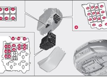
Engine compartment
242 06 Maintenance and specifications
Fuses
Engine compartment, upper
Engine compartment, front
Engine compartment, lower These fuses are all located in the engine compartment box. Fuses in
are located
under
NOTE
Fuses 16-33 are 35-41 may be changed at any time when necessary. Fuses 1-15, 34, and 42-44 are relays/circuit breakers and should only be removed or replaced by a trained and
qualified Volvo service technician.
There is a special fuse removal tool on the underside of the cover.
243 06 Maintenance and specifications
Fuses
Under the glove compartment
Fold aside the interior trim covering the fuse box.
Press the cover's lock and fold it up.
The fuses are accessible.
Positions
244 06 Maintenance and specifications
Fuses
Cargo area
Positions
Contents | Top of Page
2 0 0 8
VOLVOV70
245 06 Maintenance and specifications
Wheels and tires
Introduction
Your vehicle is equipped with tires according to the vehicle's tire information placard on the B-pillar (the structural member at the side of the vehicle, at the rear of the driver's door opening).
The tires have good road holding characteristics and offer good handling on dry and wet surfaces. It should be noted however that the tires have been developed to give these features on snow/ice-free surfaces.
Certain models are equipped with "all-season" tires, which provide a somewhat higher degree of road holding on slippery surfaces than tires without the "all-season" rating. However, for optimum road holding on icy or snow- covered roads, we recommend suitable winter tires on all four wheels.
When replacing tires, be sure that the new tires are the same size designation, type (radial) and preferably from the same manufacturer, on all four wheels. Otherwise there is a risk of altering the car's roadholding and handling characteristics.
Storing wheels and tires When storing complete wheels (tires mounted on rims), they should be suspended off the floor or placed on their sides on the floor.
Tires not mounted on rims should be stored on their sides or standing upright, but should not be suspended.
CAUTION
Tires should preferably be stored in a cool, dry, dark place, and should never be stored in close proximity to solvents, gasoline, oils, etc.
Tread wear indicator
The tires have wear indicator strips running across or parallel to the tread. The letters TWI are printed on the side of the tire. When approximately 1/16" (1.6 mm) is left on the tread, these strips become visible and indicate that the tire should be replaced. Tires with less than 1/16" (1.6 mm) tread offer very poor traction.
When replacing worn tires, it is recommended that the tire be identical in type (radial) and size as the one being replaced. Using a tire of the same make (manufacturer) will prevent alteration of the driving characteristics of the vehicle.
WARNING
The wheel and tire sizes for your Volvo are specified to meet stringent stability and handling requirements.
Unapproved wheel/tire size combinations can negatively affect your vehicle's stability and handling. Approved tire sizes are shown in the Tire inflation pressure tables beginning on page 250.
Any damage caused by installation of unapproved wheel/tire size combinations will not be covered by your new
vehicle warranty. Volvo assumes no responsibility for death, injury, or expenses that may result from such installations.
246 06 Maintenance and specifications
Wheels and tires
New tires
Remember that tires are perishable goods. As of 2000, the manufacturing week and year (Department of Transportation (DOT) stamp) will be indicated with 4 digits (e.g. 1502 means that the tire illustrated was manufactured during week 15 of 2002).
Tire age
Tires degrade over time, even when they are not being used. It is recommended that tires generally be replaced after
6 years of normal service. Heat caused by hot climates, frequent high loading conditions or Ultra Violet (U.V.) exposure can accelerate the aging process.
You should replace the spare tire when you replace the other road tires due to the aging of the spare. A tire's age can be determined by the DOT stamp on the sidewall (see the illustration). A tire with e.g., visible cracks or discoloration should be replaced immediately.
Improving tire economy
Maintain correct tire pressure. See the tire pressure tables beginning on page 250. Drive smoothly: avoid fast starts, hard braking and tire screeching. Tire wear increases with speed. Correct front wheel alignment is very important.
Unbalanced wheels impair tire economy and driving comfort. Tires must maintain the same direction of rotation throughout their lifetime. When replacing tires, the tires with the most tread should be mounted on the rear wheels to reduce the chance of
oversteer during hard braking.
Hitting curbs or potholes can damage the tires and/or wheels permanently.
247 06 Maintenance and specifications
Wheels and tires
Tire inflation
Tire inflation Check tire inflation pressure regularly.
Tables listing the recommended inflation pressure for your vehicle can be found on pages 250 and 251. A tire inflation pressure placard is also located on the driver's side Bpillar (the structural member at the side of the vehicle, at the rear of the driver's door opening). This placard indicates the designation of the factory-mounted tires on your vehicle, as well as load limits and inflation pressure.
NOTE
The placards shown indicate inflation pressure for the tires installed on the vehicle at the factory only. A certain amount of air seepage from the tires occurs naturally and tire pressure fluctuates with seasonal changes
in temperature. Always check tire pressure regularly.
Use a tire gauge to check the tire inflation pressure, including the spare, at least once a month and before long trips.
You are strongly urged to buy a reliable tire pressure gauge, as automatic service station gauges may be inaccurate.
Use the recommended cold inflation pressure for optimum tire performance and wear. Under-inflation or over-inflation may cause uneven treadwear patterns.
WARNING
Under-inflation is the most common cause of tire failure and may result in severe tire cracking, tread separation,
or "blowout," with unexpected loss of vehicle control and increased risk of injury.
Under-inflated tires reduce the load carrying capacity of your vehicle.
When weather temperature changes occur, tire inflation pressures also change. A 10-degree temperature drop causes a corresponding drop of 1 psi (7 kPa) in inflation pressure. Check your tire pressures frequently and adjust them to the proper pressure, which can be found on the vehicle's tire information placard or certification label.
Checking tire pressure Cold tires Inflation pressure should be checked when the tires are cold.
The tires are considered to be cold when they have the same temperature as the surrounding (ambient) air.
248 06 Maintenance and specifications
Wheels and tires
This temperature is normally reached after the vehicle has been parked for at least 3 hours.
After driving a distance of approximately 1 mile (1.6 km), the tires are considered to be hot. If you have to drive farther than this distance to pump your tire(s), check and record the tire pressure first and add the appropriate air pressure when you get to the pump.
If checking tire pressure when the tire is hot, never "bleed" or reduce air pressure. The tires are hot from driving and it is normal for pressures to increase above recommended cold pressures. A hot tire at or below recommended cold inflation pressure could be significantly under-inflated.
To check inflation pressure: 1. Remove the cap from the valve on one tire, then firmly press the tire gauge onto the valve.
2. Add air to reach the recommended air pressure.
3. Replace the valve cap.
4. Repeat this procedure for each tire, including the spare.
5. Visually inspect the tires to make sure there are no nails or other objects embedded that could puncture the tire and cause an air leak.
6. Check the sidewalls to make sure there are no gouges, cuts, bulges or other irregularities.
NOTE
If you overfill the tire, release air by pushing on the metal stem in the center of the valve. Then recheck the
pressure with your tire gauge.
Some spare tires require higher inflation pressure than the other tires. Consult the tire inflation tables beginning on
page 250 or see the inflation pressure placard.
249 06 Maintenance and specifications
Wheels and tires
Tire specifications
Speed ratings The speed ratings in the table below translate as follows:
Load ratings The speed ratings in the table below translate as follows:
See also page 254 for an explanation of the designations on the sidewall of the tire.
250 06 Maintenance and specifications
Wheels and tires
Tire inflation pressure table - U.S. models
The following tire pressures are recommended by Volvo for your vehicle. Refer to the tire inflation placard for information specific to the tires installed on your vehicle at the factory.
NOTE
A certain amount of air seepage from the tires occurs naturally and tire pressure fluctuates with seasonal changes in temperature. Always check tire pressure regularly.
251 06 Maintenance and specifications
Wheels and tires
Tire inflation pressure table - Canadian models
The following tire pressures are recommended by Volvo for your vehicle. Refer to the tire inflation placard for information specific to the tires installed on your vehicle at the factory.
NOTE
A certain amount of air seepage from the tires occurs naturally and tire pressure fluctuates with seasonal changes in temperature. Always check tire pressure regularly.
252 06 Maintenance and specifications
Wheels and tires
Tire Pressure Monitoring System (TPMS)-U.S models only
The tire pressure monitoring system uses sensors mounted in the tire valves to check inflation pressure levels. When the vehicle is moving at a speed of approximately 20 mph (30 km/h) or faster, these sensors transmit inflation pressure data to a receiver located in the vehicle.
NOTE
USA - FCC ID: KR5S122780002
This device complies with part 15 of the FCC rules. Operation is subject to the following conditions: (1) This device may not cause harmful interference, and (2) this device must accept any interference received, including interference that may cause undesired operation.When low inflation pressure is detected, TPMS will light up the tire pressure warning light ( a telltale) in the instrument panel, and will display a message in the text window. The wording of this message is determined by the degree of inflation pressure loss.
) (also referred to as
NOTE
If a fault occurs in TPMS, the tire pressure warning light will flash for approximately 1 minute and TIRE PRESS
SYST SERVICE REQUIRED will be displayed.
Each tire, including the spare (if provided), should be checked monthly when cold and inflated to the inflation pressure recommended by the vehicle manufacturer on the vehicle placard or tire inflation pressure label. (If your vehicle has tires of a different size than the size indicated on the vehicle placard or tire inflation pressure label, you should determine the proper tire inflation pressure for those tires.)
As an added safety feature, your vehicle has been equipped with a tire pressure monitoring system (TPMS) that illuminates a low tire pressure telltale when one or more of your tires is significantly under-inflated. Accordingly, when the low tire pressure telltale illuminates, you should stop and check your tires as soon as possible, and inflate them to the proper pressure. Driving on a significantly under-inflated tire causes the tire to overheat and can lead to tire failure. Under-inflation also reduces fuel efficiency and tire tread life, and may affect the vehicle's handling and stopping ability.
Please note that the TPMS is not a substitute for proper tire maintenance, and it is the driver's responsibility to maintain correct tire pressure, even if under-inflation has not reached the level to trigger illumination of the TPMS low tire pressure telltale.
Your vehicle has also been equipped with a TPMS malfunction indicator to indicate when the system is not operating properly. The TPMS malfunction indicator is combined with the low tire pressure telltale. When the system detects a malfunction, the telltale will flash for approximately one minute and then remain continuously illuminated. This sequence will continue upon subsequent vehicle start-ups as long as the malfunction exists. When the malfunction indicator is illuminated, the system may not be able to detect or signal low tire pressure as intended. TPMS malfunctions may occur for a variety of reasons, including the installation of replacement or alternate tires or wheels on the vehicle that prevent the TPMS from functioning properly. Always check the TPMS malfunction telltale after replacing one or more tires or wheels on your vehicle to ensure that the replacement or alternate tires and wheels allow the TPMS to continue to function properly.
253 06 Maintenance and specifications
Wheels and tires
NOTE
TPMS indicates low tire pressure but does not replace normal tire maintenance. For information on correct tire
pressure, please refer to the tables beginning on page 250, or consult your Volvo retailer.
The tire pressure warning light will not identify which tire is under-inflated. Be sure to check all four tires. A certain amount of air seepage from the tires occurs naturally and tire pressure fluctuates with seasonal changes
in temperature. Always check tire pressure regularly.
Erasing warning messages When a low tire pressure warning message has been displayed, and the tire pressure warning light has come on:
1. Use a tire pressure gauge to check the inflation pressure of all four tires.
2. Re-inflate the tire(s) to the correct pressure (consult the tire pressure placard or the tables beginning on page 250).
3. In certain cases, it may be necessary to drive the vehicle for several minutes at a speed of 20 mph (30 km/h) or faster. This will erase the warning text and the warning light will go out.
WARNING
Incorrect inflation pressure could lead to tire failure, resulting in a loss of control of the vehicle.
Changing wheels with TPMS Please note the following when changing or replacing the factory installed TPMS wheels/tires on the vehicle:
Only the factory-mounted wheels are equipped with TPMS sensors in the valves. If the vehicle is equipped with a temporary spare tire, this tire does not have a TPMS sensor. If wheels without TPMS sensors are mounted on the vehicle, TIRE PRESS SYST SERVICE REQUIRED will be
displayed each time the vehicle is driven above 25 mph (40 km/h) for 10 minutes or more.
Once TPMS sensors are properly installed, the warning message should not reappear. If the message is still displayed, drive the vehicle for several minutes at a speed of 20 mph (30 km/h) or faster to erase the message.
Volvo recommends that TPMS sensors be fitted on all wheels used on the vehicle. Volvo does not recommend
moving sensors back and forth between sets of wheels.
NOTE
If you change to tires with a different recommended inflation pressure, the TPMS system must be recalibrated to
these tires. This must be done by a trained and qualified Volvo service technician.
If a tire is changed, or if the TPMS sensor is moved to another wheel, the sensor's seal, nut, and valve core should
be replaced.
When installing TPMS sensors, the vehicle must be parked for at least 15 minutes with the ignition off. if the
vehicle is driven within 15 minutes, a TPMS error message will be displayed.
CAUTION
When inflating tires with TPMS valves, press the pump's mouthpiece straight onto the valve to help avoid bending or otherwise damaging the valve.
254 06 Maintenance and specifications
Wheels and tires
Tire designations
Federal law mandates that tire manufacturers place standardized information on the sidewall of all tires (see the illustration).
The following information is listed on the tire sidewall:
The tire designation (the following figures are examples of a tire designation):
1. 215: the width of the tire (in millimeters) from sidewall edge to sidewall edge. The larger the number, the wider the tire.
2. 65: The ratio of the tire's height to its width.
3. R: Radial tire.
4. 15: The diameter of the wheel rim (in inches).
5. 95: The tire's load index. In this example, a load index of 95 equals a maximum load of 1521 lbs (690 kg).
6. H: The tire's speed rating, or the maximum speed at which the tire is designed to be driven for extended periods of time, carrying a permissible load for the vehicle, and with correct inflation pressure. For example, H indicates a speed rating of 130 mph (210 km/h).
NOTE
This information may not appear on the tire because it is not required by law.
7. M+S or M/S = Mud and Snow, AT = All Terrain, AS = All Season
8. U.S. DOT Tire Identification Number (TIN): This begins with the letters "DOT" and indicates that the tire meets all federal standards. The next two numbers or letters are the plant code where it was manufactured, the next two are the tire size code and the last four numbers represent the week and year the tire was built. For example, the numbers 317 mean the 31st week of 1997. After 2000 the numbers go to four digits. For example, 2501 means the 25th week of 2001. The numbers in between are marketing codes used at the manufacturer's discretion. This information helps a tire manufacturer identify a tire for safety recall purposes.
9. Tire Ply Composition and Material Used: Indicates the number of plies indicates or the number of layers of rubber-coated fabric in the tire tread and sidewall. Tire manufacturers also must indicate the ply materials in the tire and the sidewall, which include steel, nylon, polyester, and others.
10. Maximum Load: Indicates the maximum load in pounds and kilograms that can be carried by the tire. Refer to the vehicle's tire information placard or the safety certification label, located on the B-Pillar or the driver's door or on the inside of the fuel filler door on Canadian models, for the correct tire pressure for your vehicle.
11. Treadwear, Traction, and Temperature grades: See page 258 for more information.
12. Maximum permissible inflation pressure: the greatest amount of air pressure that should ever be put in the tire. This limit is set by the tire manufacturer.
255 06 Maintenance and specifications
Wheels and tires
Glossary of tire terminology
The tire suppliers may have additional markings, notes or warnings such as standard load, radial tubeless, etc.
Tire information placard: A placard showing the OE (Original Equipment) tire sizes, recommended inflation
pressure, and the maximum weight the vehicle can carry.
Tire Identification Number (TIN): A number on the sidewall of each tire providing information about the tire
brand and manufacturing plant, tire size and date of manufacturer.
Inflation pressure: A measure of the amount of air in a tire. Standard load: A class of P-metric or Metric tires designed to carry a maximum load at 35 psi [37 psi (2.5 bar) for Metric tires]. Increasing the inflation pressure beyond this pressure will not increase the tires load carrying capability. Extra load: A class of P-metric or Metric tires designed to carry a heavier maximum load at 41 psi [43 psi (2.9 bar)
for Metric tires]. Increasing the inflation pressure beyond this pressure will not increase the tire's load carrying capability.
kPa: Kilopascal, a metric unit of air pressure. PSI: Pounds per square inch, a standard unit of air pressure. B-pillar: The structural member at the side of the vehicle behind the front door. Bead area of the tire: Area of the tire next to the rim. Sidewall of the tire: Area between the bead area and the tread. Tread area of the tire: Area of the perimeter of the tire that contacts the road when mounted on the vehicle. Rim: The metal support (wheel) for a tire or a tire and tube assembly upon which the tire beads are seated. Maximum load rating: a figure indicating the maximum load in pounds and kilograms that can be carried by the
tire. This rating is established by the tire manufacturer.
Maximum permissible inflation pressure: the greatest amount of air pressure that should ever be put in the tire.
This limit is set by the tire manufacturer.
Recommended tire inflation pressure: inflation pressure, established by Volvo, which is based on the type of tires
that are mounted on a vehicle at the factory. This inflation pressure is affected by the number of occupants in the vehicle, the amount of cargo, and the speed at which the vehicle will be driven for a prolonged period. This information can be found on the tire inflation placard(s) located on the driver's side B-pillar or on the inside of the fuel filler door on Canadian models, and in the tire inflation table in this chapter.
Cold tires: The tires are considered to be cold when they have the same temperature as the surrounding (ambient)
air. This temperature is normally reached after the vehicle has been parked for at least 3 hours.
256 06 Maintenance and specifications
Wheels and tires
Vehicle loading
Properly loading your vehicle will provide maximum return of vehicle design performance.
Before loading your vehicle, familiarize yourself with the following terms for determining your vehicle's weight ratings, with or without a trailer, from the vehicle's Federal/Canadian Motor Vehicle Safety Standards (FMVSS/CMVSS) label, and the vehicle's tire information placard:
Curb weight The weight of the vehicle including a full tank of fuel and all standard equipment. It does not include passengers, cargo, or optional equipment.
Capacity weight All weight added to the curb weight, including cargo and optional equipment. When towing, trailer hitch tongue load is also part of cargo weight.
NOTE
For trailer towing information, please refer to the section "Towing a trailer" on page 213.
Permissible axle weight The maximum allowable weight that can be carried by a single axle (front or rear). These numbers are shown on the Federal/Canadian Motor Vehicle Safety Standards (FMVSS/CMVSS) label. The total load on each axle must never
exceed its maximum permissible weight.
Gross vehicle weight (GVW) The vehicle's curb weight + cargo + passengers.
NOTE
The location of the various labels in your vehicle can be found on page 270. A table listing important weight limits for your vehicle can be found on page 274.
Steps for Determining Correct Load Limit 1. Locate the statement ''the combined weight of occupants and cargo should never exceed XXX pounds'' on your vehicle's placard.
2. Determine the combined weight of the driver and passengers that will be riding in your vehicle.
3. Subtract the combined weight of the driver and passengers from XXX kilograms or XXX pounds.
4. The resulting figure equals the available amount of cargo and luggage load capacity. For example, if the ''XXX'' amount equals 1400 lbs. and there will be five 150 lb. passengers in your vehicle, the amount of available cargo and luggage load capacity is 650 lbs. (1400-750 (5 x 150) = 650 lbs.)
5. Determine the combined weight of luggage and cargo being loaded on the vehicle. That weight may not safely exceed the available cargo and luggage load capacity calculated in Step 4.
6. If your vehicle will be towing a trailer, load from your trailer will be transferred to your vehicle. Consult this manual1 to determine how this reduces the available cargo and luggage load capacity of your vehicle.
1See "Towing a trailer" on page 213.
257 06 Maintenance and specifications
Wheels and tires
WARNING
Exceeding the permissible axle weight, gross vehicle weight, or any other weight rating limits can cause tire
overheating resulting in permanent deformation or catastrophic failure.
Do not use replacement tires with lower load carrying capacities than the tires that were original equipment on the vehicle because this will lower the vehicle's GVW rating. Replacement tires with a higher limit than the originals do not increase the vehicle's GVW rating limitations.
258 06 Maintenance and specifications
Wheels and tires
Uniform Tire Quality Grading
ALL PASSENGER VEHICLE TIRES MUST CONFORM TO FEDERAL SAFETY REQUIREMENTS IN ADDITION TO THESE GRADES
Quality grades can be found, where applicable, on the tire sidewall between the tread shoulder and maximum section width. For example:
Treadwear 200 Traction AA Temperature A
TREADWEAR The treadwear grade is a comparative rating based on the wear rate of the tire when tested under controlled conditions on a specified government test course. For example, a tire graded 150 would wear one and one half (1 1/2) times as well on the government course as a tire graded 100. The relative performance of tires depends upon the actual conditions of their use, however, and many depart significantly from the norm due to variation in driving habits, maintenance practices and differences in road characteristics and climate.
TRACTION The traction grades, from highest to lowest, are AA, A, B, and C, as measured under controlled conditions on specified government test surfaces of asphalt and concrete. A tire marked C may have poor traction performance. The traction grade assigned to this tire is based on braking (straight-ahead) traction tests and is not a measure of cornering (turning) traction.
WARNING
The traction grade assigned to this tire is based on braking (straight-ahead) traction tests and is not a measure of cornering (turning) traction.
TEMPERATURE The temperature grades are AA (the highest), A, B, and C, representing the tire's resistance to the generation of heat and its ability to dissipate heat when tested under controlled conditions on a specified indoor laboratory test wheel. Sustained high temperature can cause the material of the tire to degenerate and reduce tire life, and excessive temperature can lead to sudden tire failure. The grade C corresponds to a minimum level of performance that all passenger vehicle tires must meet under the Federal Motor Safety Standard No. 109. Grades B and A represent higher levels of performance on the laboratory test wheel than the minimum required by law.
WARNING
The temperature grade for this tire is established for a tire that is properly inflated and not overloaded. Excessive speed, under-inflation, or excessive loading, either separately or in combination, can cause heat buildup and tire failure.
259 06 Maintenance and specifications
Wheels and tires
Snow chains, snow tires, studded tires
Snow chains Snow chains can be used on your Volvo with the following restrictions:
Snow chains should be installed on front wheels only. Use only Volvo approved snow chains. If accessory, aftermarket or "custom" tires and wheels are installed and are of a size different than the original tires and wheels, chains in some cases CANNOT be used. Sufficient clearances between chains and brakes, suspension and body components must be maintained.
Some strap-on type chains will interfere with brake components and therefore CANNOT be used. All Wheel Drive models: Snow chains should only be installed on the front wheels. Only chains adapted for AWD
models should be used.
Consult your Volvo retailer for additional snow chain information.
CAUTION
Check local regulations regarding the use of snow chains before installing. Always follow the chain manufacturer's installation instructions carefully. Install chains as tightly as possible and
Never exceed the chain manufacturer's specified maximum speed limit. (Under no circumstances should you
Avoid bumps, holes or sharp turns when driving with snow chains. The handling of the vehicle can be adversely affected when driving with chains. Avoid fast or sharp turns as well
retighten periodically.
exceed 31 mph (50 km/h).
as locked wheel braking.
Snow tires, studded tires1
Tires for winter use:Owners who live in or regularly commute through areas with sustained periods of snow or icy driving conditions are
strongly advised to fit suitable winter tires to help retain the highest degree of traction.
It is important to install winter tires on all four wheels to help retain traction during cornering, braking, and
accelerating. Failure to do so could reduce traction to an unsafe level or adversely affect handling.
Do not mix tires of different design as this could also negatively affect overall tire road grip. Winter tires wear more quickly on dry roads in warm weather. They should be removed when the winter driving
season has ended.
Studded tires should be run-in 300-600 miles (500-1000 km) during which the vehicle should be driven as smoothly
as possible to give the studs the opportunity to seat properly in the tires. The tires should have the same rotational direction throughout their entire lifetime.
1Where permitted