- 2004 Volvo C70 Owners Manuals
- Volvo C70 Owners Manuals
- 2011 Volvo C70 Owners Manuals
- Volvo C70 Owners Manuals
- 1998 Volvo C70 Owners Manuals
- Volvo C70 Owners Manuals
- 2005 Volvo C70 Owners Manuals
- Volvo C70 Owners Manuals
- 2000 Volvo C70 Owners Manuals
- Volvo C70 Owners Manuals
- 2007 Volvo C70 Owners Manuals
- Volvo C70 Owners Manuals
- 2006 Volvo C70 Owners Manuals
- Volvo C70 Owners Manuals
- 2012 Volvo C70 Owners Manuals
- Volvo C70 Owners Manuals
- 2002 Volvo C70 Owners Manuals
- Volvo C70 Owners Manuals
- 2013 Volvo C70 Owners Manuals
- Volvo C70 Owners Manuals
- 2008 Volvo C70 Owners Manuals
- Volvo C70 Owners Manuals
- 2009 Volvo C70 Owners Manuals
- Volvo C70 Owners Manuals
- 1999 Volvo C70 Owners Manuals
- Volvo C70 Owners Manuals
- 2001 Volvo C70 Owners Manuals
- Volvo C70 Owners Manuals
- 2003 Volvo C70 Owners Manuals
- Volvo C70 Owners Manuals
- Download PDF Manual
-
• Engine damage will occur if water is
drawn into the air cleaner.
• If the vehicle is driven through water deeper than 9 in (25 cm), water may enter the differential and the transmis- sion. This reduces the oil's lubricating capacity and may shorten the service life of these components.
• Do not allow the vehicle to stand in water up to the door sills longer than absolutely necessary. This could result in electrical malfunctions.
• If the engine has been stopped while the car is in water, do not attempt to restart the engine. Have the car towed out of the water.
Cold weather precautions If you wish to check your vehicle before the approach of cold weather, the following advice is worth noting: • Make sure that the engine coolant contains
50 percent antifreeze. Any other mixture will reduce freeze protection. This gives protection against freezing down to –31 °F (–35 °C). See section "Coolant". The use of "recycled" antifreeze is not approved by
06 Starting and driving
General information
Volvo. Different types of antifreeze must not be mixed.
• Volvo recommends using only genuine
Volvo antifreeze in your vehicle's radiator. Your Volvo retailer stocks plenty of Volvo engine coolant to help protect your vehicle during cold weather.
• Try to keep the fuel tank well filled – this
prevents the formation of condensation in the tank. In addition, in extremely cold weather conditions it is worthwhile to add fuel line de-icer before refueling.
• The viscosity of the engine oil is important. Oil with low viscosity (thinner oil) improves cold-weather starting as well as decreas- ing fuel consumption while the engine is warming up. For winter use, 5W-30 oil, par- ticularly the synthetic type1, is recom- mended. Be sure to use good quality oil but do not use cold-weather oil for hard driving or in warm weather, see page 262 for more information.
• The load placed on the battery is greater during the winter since the windshield wip- ers, lighting, etc. are used more often. Moreover, the capacity of the battery decreases as the temperature drops. In very cold weather, a poorly charged bat- tery can freeze and be damaged. It is there- fore advisable to check the state of charge
1 Synthetic oil is not used when the oil is changed at the normal maintenance intervals except at owner request and at additional charge. Please consult your Volvo retailer.
06
}}
133
06 Starting and driving
General information
more frequently and spray an anti-rust oil on the battery posts.
• Volvo recommends the use of snow tires on all four wheels for winter driving – see the chapter "Wheels and tires."
• To prevent the washer fluid reservoir from freezing, add washer solvents containing antifreeze (see page 209 for the location of the washer fluid reservoir). This is impor- tant since dirt is often splashed on the windshield during winter driving, requiring the frequent use of the washers and wip- ers. Volvo Washer Solvent should be dilu- ted as follows: Down to 14 °F (–10 °C): 1
part washer solvent and 4 parts water Down to 5° F (–15° C): 1 part washer sol- vent and 3 parts water Down to 0° F (–18° C): 1 part washer solvent and 2 parts water Down to –18° F (–28° C): 1 part washer solvent and 1 part water.• Use Volvo Teflon Lock Spray in the locks.
NOTE
Avoid using de-icing sprays as they can cause damage to the locks.
Conserving electrical current Keep the following in mind to help minimize battery drain: • When the engine is not running, avoid turn-
ing the ignition key to position II. Many electrical systems (the audio system, the optional navigation system, power win- dows, etc) will function with the ignition key in position I. This position reduces drain on the battery.
• Please keep in mind that using systems,
accessories, etc that consume a great deal of current when the engine is not running could result in the battery being completely drained.
• The optional 12 volt socket in the trunk (certain models only) provides electrical current even with the ignition switched off, which drains the battery.
NOTE
• If the ignition is switched on, a warning
message will be displayed in the text window in the instrument panel when the battery charge is low.
• An energy conserving function
designed into the vehicle's electrical system will switch off certain functions or reduce the load on the battery by, e.g., reducing the audio system's vol- ume.
Before a long distance trip It is always worthwhile to have your vehicle checked at a trained and qualified Volvo serv- ice technician before driving long distances. Your trained and qualified Volvo service tech- nician will also be able to supply you with bulbs, fuses, spark plugs and wiper blades for your use in the event that problems occur. As a minimum, the following items should be checked before any long trip: • Check that engine runs smoothly and that
fuel consumption is normal.
• Check for fuel, oil, and fluid leakage • Have the transmission oil level checked2. • Check condition of drive belts.
2 To prevent injury from contact with hot surfaces, do not inspect your vehicle's transmission fluid yourself. Have your vehicle's transmission fluid level inspected by a qualified Volvo service technician.
06
134
• Check state of the battery's charge. • Examine tires carefully (the spare tire as well), and replace those that are worn. Check tire pressures.
• The brakes, front wheel alignment, and
steering gear should be checked by your Volvo retailer only.
• Check all lights, including high beams. • Reflective warning triangles are legally
required in some states/provinces.
• Have a word with your Volvo retailer if you intend to drive in countries where it may be difficult to obtain the correct fuel.
• Consider your destination. If you will be
driving through an area where snow or ice are likely to occur, consider snow tires.
06 Starting and driving
General information
06
135
06 Starting and driving
Fuel requirements
Octane rating
Minimum octane
Typical pump octane label Volvo recommends premium fuel for best per- formance, but using 87 octane or above will not affect engine reliability. Volvo engines are designed to achieve rated horsepower, torque, and fuel economy per- formance using premium 91 octane fuel.
Demanding driving In demanding driving conditions, such as oper- ating the vehicle in hot weather, towing a trailer, or driving for extended periods at higher alti- tudes than normal, it may be advisable to switch to higher octane fuel (91 or higher) or to change gasoline brands to fully utilize your
06
136
engine's capacity, and for the smoothest pos- sible operation.
NOTE
When switching to higher octane fuel or changing gasoline brands, it may be neces- sary to fill the tank more than once before a difference in engine operation is noticeable.
Fuel Formulations Do not use gasoline that contains lead as a knock inhibitor, and do not use lead additives. Besides damaging the exhaust emission con- trol systems on your vehicle, lead has been strongly linked to certain forms of cancer. Many fuels contain benzene as a solvent. Unburned benzene has been strongly linked to certain forms of cancer. If you live in an area where you must fill your own gas tank, take precautions. These may include: • standing upwind away from the filler nozzle
while refueling
• refueling only at gas stations with vapor
recovery systems that fully seal the mouth of the filler neck during refueling
• wearing neoprene gloves while handling a
fuel filler nozzle.
Use of Additives With the exception of gas line antifreeze during winter months, do not add solvents, thicken- ers, or other store-bought additives to your vehicle's fuel, cooling, or lubricating systems. Overuse may damage your engine, and some of these additives contain organically volatile chemicals. Do not needlessly expose yourself to these chemicals.
WARNING
Never carry a cell phone that is switched on while refueling your vehicle. If the phone rings, this may cause a spark that could ignite gasoline fumes, resulting in fire and injury.
WARNING
Carbon monoxide is a poisonous, colorless, and odorless gas. It is present in all exhaust gases. If you ever smell exhaust fumes inside the vehicle, make sure the passenger compartment is ventilated, and immediately return the vehicle to a trained and qualified Volvo service technician for correction.
Deposit control gasoline (detergent additives) Volvo recommends the use of detergent gas- oline to control engine deposits. Detergent gasoline is effective in keeping injectors and intake valves clean. Consistent use of deposit control gasolines will help ensure good driva- bility and fuel economy. If you are not sure whether the gasoline contains deposit control additives, check with the service station oper- ator.
NOTE
Volvo does not recommend the use of store-bought fuel injector cleaning addi- tives.
Unleaded fuel Each Volvo has a three-way catalytic converter and must use only unleaded gasoline. U.S. and Canadian regulations require that pumps deliv- ering unleaded gasoline be labelled "UNLEA- DED". Only these pumps have nozzles which fit your vehicle's filler inlet. It is unlawful to dis- pense leaded fuel into a vehicle labelled "unleaded gasoline only". Leaded gasoline damages the three-way catalytic converter and the heated oxygen sensor system. Repeated use of leaded gasoline will lessen the effec-
tiveness of the emission control system and could result in loss of emission warranty cov- erage. State and local vehicle inspection pro- grams will make detection of misfueling easier, possibly resulting in emission test failure for misfueled vehicles.
NOTE
Some U.S. and Canadian gasolines contain an octane enhancing additive called methyl- cyclopentadienyl manganese tricarbonyl (MMT). If such fuels are used, your Emission Control System performance may be affec- ted, and the Check Engine Light (malfunc- tion indicator lamp) located on your instru- ment panel may light. If this occurs, please return your vehicle to a trained and qualified Volvo service technician for maintenance.
Gasoline containing alcohol and ethers Some fuel suppliers sell gasoline containing "oxygenates" which are usually alcohols or ethers. In some areas, state or local laws require that the service pump be marked indi- cating use of alcohols or ethers. However, there are areas in which the pumps are unmarked. If you are not sure whether there is alcohol or ethers in the gasoline you buy, check with the service station operator. To meet sea- sonal air quality standards, some areas require the use of "oxygenated" fuel. Volvo allows the
06 Starting and driving
Fuel requirements
use of the following "oxygenated" fuels; how- ever, the octane ratings listed on this page must still be met. Alcohol – Ethanol: Fuels containing up to 10% ethanol by volume may be used. Ethanol may also be referred to as Ethyl alcohol, or "Gasohol". Ethers – MTBE: Fuels containing up to 15% MTBE may be used.
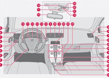
Fuel filler door Press the button on the light switch panel (see the illustration on page 59) with the ignition switched off to unlock the fuel filler door. Please note that the fuel filler door will remain unlocked until the vehicle begins to move for- ward. An audible click will be heard when the fuel filler door relocks. If you intend to leave your vehicle while it is being refueled, this feature enables you to lock the doors/trunk while leaving the fuel filler door unlocked. You can also keep the vehicle locked if you remain inside it during refueling. The central locking button does not lock the fuel filler door. Be sure the fuel filler door is not obstructed and is completely closed after refueling. Open the fuel filler cap slowly during hot weather.
06
}}
137
under the New Vehicle Limited War- ranty.
06 Starting and driving
Fuel requirements
Refueling The fuel tank is designed to accommodate possible expansion of the fuel in hot weather, see page 260 for fuel tank volume. Be aware that the "usable" tank capacity will be some- what less than the specified maximum. When the fuel level is low, such factors as ambient temperature, the fuel's "Reid vapor pressure" characteristics, and terrain can affect the fuel pump's ability to supply the engine with an adequate supply of fuel. Therefore, it is advis- able to refuel as soon as possible when the needle nears the red zone, or when the fuel warning light comes on.
CAUTION
• Do not refuel with the engine running1. Turn the ignition off or to position I. If the ignition is on, an incorrect reading could occur in the fuel gauge
• After refueling, close the fuel filler cap by turning it clockwise until it clicks into place.
• Avoid overfilling the fuel tank. Do not press the handle on the filler nozzle more than one extra time. Too much fuel in the tank in hot weather conditions can cause the fuel to overflow. Overfill- ing could also cause damage to the emission control systems.
• Avoid spilling gasoline during refueling.
In addition to causing damage to the environment, gasolines containing alcohol can cause damage to painted surfaces, which may not be covered under the New Vehicle Limited War- ranty.
• Do not use gasolines containing meth-
anol (methyl alcohol, wood alcohol). This practice can result in vehicle per- formance deterioration and can dam- age critical parts in the fuel system. Such damage may not be covered
1 If the fuel filler cap is not closed tightly or if the engine is running when the vehicle is refueled, the Check Engine Light (malfunction indicator lamp) may indicate a fault. However, your vehicle’s
performance will not be affected. Use only Volvo original or approved fuel filler caps.
06
138
06 Starting and driving
Ignition switch
II – Drive position
The key's position when driv- ing. The vehicle's entire elec- trical system is activated.
III – Start position
Turn the key to this position and release it immediately. The key returns automatically to the Drive position. A chime will sound if the key is left in the ignition and the
driver's door is opened (does not apply to vehi- cles with the optional keyless drive).
Ignition switch positions
0 – Locked position
Remove the key to lock the steering wheel1. Never turn the key to position 0 while driving or when the vehicle is being towed.
NOTE
A ticking sound may be audible if the key is turned to a position between 0 and I. To stop this sound, turn the key to position II and back to position 0.
I – Intermediate position2
Certain accessories, radio, etc. on, daytime running lights off.
1 Automatic transmission: the gear selector must be in the Park position. The optional keyless drive start control does not need to be removed. 2 Please be aware that leaving the key in this positions I or II will increase battery drain.
06
139
06 Starting and driving
Starting the vehicle
To start the engine
WARNING
Before starting, check that the seat, steering wheel and mirrors are adjusted properly. Make sure the brake pedal can be depressed completely. Adjust the seat if necessary.
1. Fasten the seat belt. 2. Apply the parking brake if not already set. The gear selector should be locked in the Park (P) position (Shiftlock). See also page 146. Manual transmission: The clutch must be fully depressed.
NOTE
After a cold start, idle speed may be notice- ably higher than normal for a short period. This is done to help bring components in the emission control system to their normal operating temperature as quickly as possi- ble, which enables them to control emis- sions and help reduce the vehicle's impact on the environment.
3. The vehicle is equipped with an autostart
feature. Without touching the throttle
pedal, turn the key to position III and release it. The starter motor will then oper- ate automatically (for up to ten seconds) until the engine starts. If the engine fails to start, repeat this step.
4. To release the gear selector from the Park (P) position, the engine must be running (or the ignition key must be in position II) and the brake pedal must be depressed.
5. Select the desired gear. On models with an automatic transmission, the gear engages after a very slight delay which is especially noticeable when selecting R.
NOTE
• Immobilizer: If two of the keys to your vehicle are close together, e.g., on the same key ring when you try to start the vehicle, this could cause interference in the immobilizer system and result in the vehicle not starting. If this should occur, remove one of the keys from the key ring before trying to start the vehicle again.
• Keylock: Models equipped an auto-
matic transmission have a keylock sys- tem. When the engine is switched off, the gear selector must be in the Park (P) position before the key can be removed from the ignition switch1. • When starting in cold weather, the transmission may shift up at slightly higher engine speeds than normal until the automatic transmission fluid rea- ches normal operating temperature.
• Do not race a cold engine immediately
after starting. Oil flow may not reach some lubrication points fast enough to prevent engine damage.
1 The optional keyless drive start control does not need to be removed from the ignition switch.
06
140
WARNING
Volvo's floor mats are specially manufac- tured for your car. They must be firmly secured in the clips on the floor so that they cannot slide and become trapped under the pedals on the driver's side. • Always place the gear selector in Park (P) (manual transmission: first or reverse gear) and apply the parking brake before leaving the vehicle.and apply the parking brake before leaving the vehi- cle. Never leave the vehicle unattended with the engine running.
• Always open garage doors fully before starting the engine inside a garage to ensure adequate ventilation. The exhaust gases contain carbon monox- ide, which is invisible and odorless but very poisonous.
CAUTION
Automatic transmission: The engine should be idling when you move the gear selector. Never accelerate until after you feel the transmission engage! Accelerating immediately after selecting a gear will cause harsh engagement and premature trans- mission wear. Selecting P or N when idling at a standstill for prolonged periods of time will help prevent overheating of the auto- matic transmission fluid.
06 Starting and driving
Starting the vehicle
06
141
06 Starting and driving
Starting the vehicle with keyless drive (option as available)
Starting a vehicle with keyless drive
NOTE
A keyless drive remote control must be inside the vehicle in order to start the engine.
1. Press the brake pedal (the clutch pedal must also be fully depressed on models with a manual transmission).
2. Press in the keyless drive start control and
turn it to position III.
NOTE
The vehicle is equipped with an autostart function that makes it possible to start the engine without holding the start control in position III. Turn the start control to position III and release it. The starter motor will then operate automatically (for up to ten sec- onds) until the engine starts.
3.
Starting the vehicle with the ignition key (remote control) A vehicle with keyless drive can also be started with the ignition key (if, for example, the battery in the keyless drive remote control is weak). To do so:
Removing the keyless drive start control 1. Press the catch on the side of the start
control (see the illustration).
2. Pull the keyless drive start control out of
the ignition switch. Insert the remote control into the ignition switch and turn it to position III to start the engine. See also page 140 for complete starting information.
Starting a vehicle with keyless drive Keyless drive makes it possible to unlock, start and lock the vehicle without using a remote control. A start control is fitted in the ignition switch on vehicles equipped with the optional keyless drive. This control is used in the same way as the ignition key to start the engine. See also page 140 for general information on starting the engine.
06
142
06 Starting and driving
Manual transmission, 6-speed (certain markets only)
6-speed manual transmission (option on certain models)
Engaging reverse gear, 6-speed transmission
CAUTION
Never shift into reverse while moving for- ward.
WARNING
An extra mat on the driver's floor can cause the accelerator, brake, and/or clutch pedal to catch. Check that the movement of these pedals is not impeded. Not more than one protective floor covering may be used at one time.
Depress the clutch pedal completely when changing gears1. Remove your foot from the clutch pedal while driving. The shift pattern should be followed. Overdrive (5th and 6th gears) should be used as often as possible to help improve fuel econ- omy.
Reverse gear should only be engaged from a complete stop.
NOTE
Reverse gear is electronically blocked to help prevent it from being selected while the vehicle is moving foward.
1 Clutch interlock: The clutch must be fully depressed before you can start your car. If the clutch is notdepressed, it will not be possible to start the engine.
06
143
06 Starting and driving
Automatic transmission (option)
Shiftgate positions
Gear selector positions
P – Park Select the P position when starting or parking. In P, the transmission is mechanically blocked (Shiftlock). Always apply the parking brake when parking.
06
Depress the button on the front of the gear selector knob to move the selector between the R, N, D, and P positions. The gear selector can be moved freely between the Geartronic (manual shifting) and Drive (D) positions while driving.
1 T5 models have 6 forward gears.
144
D - left position: automatic shifting, M - right posi- tion: manual shifting
CAUTION
The car must be stationary when selecting position P.
R – Reverse The car must be stationary when shifting to position R.
N – Neutral N is the neutral position. The engine can be started, but no gear is selected. Apply the park- ing brake when the car is stationary with the gear selector in N.
NOTE
If the gear selector is in the Neutral position and the vehicle has been at a standstill for at least 3 seconds, the brake pedal must be pressed before the gear selector can be moved to another position.
In order to move the gear selector to another position: 1. Turn the ignition key to position II (if the
engine is not already running).
2. Depress the brake pedal. 3. Move the gear selector to the desired posi-
tion.
D – Drive D is the normal driving position. The Drive posi- tion offers 5 forward gears1. The car automat- ically shifts between the various forward gears,
based on the level of acceleration and speed. The car must be at a standstill when shifting to position D from position R.
Manual shifting – Geartronic The manual shifting mode (Geartronic) can be selected at any time to manually select forward gears, including while the car is moving.
NOTE
Reverse, Neutral, and Park cannot be selected in Geartronic mode.
• To access the Manual (M) shifting position from Drive (D), move the gear selector to the right to M.
• To return to the Drive (D) position from M,
move the gear selector to the left.
While driving • If you select the M position while driving, the gear that was being used in the Drive position will also initially be selected in the M position.
• Move the gear selector forward (toward "+") to shift to a higher gear or rearward (toward "–") to shift to a lower gear.
• If you hold the gear selector toward "–", the transmission will downshift one gear at a time and will utilize the braking power of
the engine. If the current speed is too high for using a lower gear, the downshift will not occur until the speed has decreased enough to allow the lower gear to be used. • If you slow to a very low speed, the trans-
mission will automatically shift down.
Cold starts (turbo engines) When driving before the engine has reached its normal operating temperature, the transmis- sion will shift up at slightly higher engine speeds to heat the three-way catalytic con- verter as quickly as possible.
Kickdown Automatic shift to a lower gear (kickdown) is achieved by depressing the accelerator pedal fully and briskly. An upshift will occur when approaching the top speed for a particular gear or by releasing the accelerator pedal slightly. Kickdown can be used for maximum acceler- ation or when passing at highway speeds.
Safety function To help prevent excessive engine speeds (rpm) that could lead to engine damage, the engine management system includes a function that prevents kickdown from taking place if the engine speed is too high.
06 Starting and driving
Automatic transmission (option)
Kickdown will not occur if the driver attempts to use this function when engine speeds are too high. The transmission will remain in the currently selected gear.
06
145
06 Starting and driving
Shiftlock override
Overriding the shiftlock system
4.
Insert the key blade, see page 116, into the opening and press it down until it bottoms.
5. With the key blade pressed down, move
the gear selector out of the P position.
Shiftlock prevents the gear selector from being moved out of Park unless the ignition key is in position II and the brake pedal is depressed. In certain cases it may be necessary to move the gear selector from the Park position man- ually.
To manually override the Shiftlock system: 1. Apply the parking brake. 2. Depress the brake pedal. 3. There is a small cover below P-R-N-D on the gear selector panel. Open the rear edge of the panel.
06
146
Brake circuit malfunction The brake system is a hydraulic system con- sisting of two separate brake circuits. If a prob- lem should occur in one of these circuits, it is still possible to stop the vehicle with the other brake circuit. If the brake pedal must be depressed farther than normal and requires greater foot pressure, the stopping distance will be longer. A warning light in the instrument panel will light up to warn the driver that a fault has occurred. If this light comes on while driving or braking, stop immediately and check the brake fluid level in the reservoir.
NOTE
Press the brake pedal hard and maintain pressure on the pedal – do not pump the brakes.
WARNING
If the fluid level is below the MIN mark in the reservoir or if a brake system message is shown in the information display, DO NOT DRIVE. Have the vehicle towed to a Volvo retailer and have the brake system inspec- ted.
Power brakes function only when the engine is running The power brakes utilize vacuum pressure which is only created when the engine is run- ning. Never let the vehicle roll to a stop with the engine switched off. If the power brakes are not working, the brake pedal must be pressed approximately five times harder than usual to make up for the lack of power assistance. This can happen for example when towing your vehicle or if the engine is switched off when the vehicle is roll- ing. The brake pedal feels harder than usual.
Water on brake discs and brake pads affects braking Driving in rain and slush or passing through an automatic car wash can cause water to collect on the brake discs and pads. This will cause a delay in braking effect when the pedal is depressed. To avoid such a delay when the brakes are needed, depress the pedal occa- sionally when driving through rain, slush, etc. This will remove the water from the brakes. Check that brake application feels normal. This should also be done after washing or starting in very damp or cold weather.
06 Starting and driving
Brake system
Severe strain on the brake system The brakes will be subject to severe strain when driving in mountains or hilly areas, or when towing a trailer. Vehicle speed is usually slower, which means that the cooling of the brakes is less efficient than when driving on level roads. To reduce the strain on the brakes, shift into a lower gear and let the engine help with the braking. Do not forget that if you are towing a trailer, the brakes will be subjected to a greater than normal load.
Anti-lock brakes (ABS) The Anti-lock Braking System (ABS) helps to improve vehicle control (stopping and steering) during severe braking conditions by limiting brake lockup. When the system "senses" impending lockup, braking pressure is auto- matically modulated in order to help prevent lockup that could lead to a skid. The system performs a self-diagnostic test when the engine is started and when the vehicle first reaches a speed of approxi- mately 12 mph (20 km/h). The brake pedal will pulsate several times and a sound may be audible from the ABS control module. This is normal.
06
}}
147
06 Starting and driving
Brake system
For optimal ABS braking effect: 1. Press down on the brake pedal with full
force. The pedal will pulsate.
2. Steer the vehicle in the direction of travel
and keep the brake pedal depressed.
Electronic Brake Force Distribution (EBD) EBD is an integrated part of the ABS system. EBD regulates the hydraulic pressure to the rear brakes to help provide optimal braking capacity. The switching of the ABS modulator will be audible and the brake pedal will pulsate during braking. Please be aware that ABS does not increase the absolute braking potential of the vehicle. While control will be enhanced, ABS will not shorten stopping distances on slippery surfaces. If the warning lamp lights up there is a mal- function of the ABS system (the standard brak- ing system will still function) and the vehicle should be driven cautiously to a trained and qualified Volvo service technicianfor inspec- tion.
06
148
WARNING
NOTE
If the BRAKES and ABS warning symbols light at the same time, there may be a prob- lem in the brake system. If the brake fluid level is normal in these circumstances, drive carefully to a trained and qualified Volvo service technician to have the brake system checked.
Emergency Brake Assistance – EBA EBA is designed to provide full brake effect immediately in the event of sudden, hard brak- ing. The system is activated by the speed with which the brake pedal is depressed. When the EBA system is activated, the brake pedal will go down and pressure in the brake system immediately increases to the maximum level. Maintain full pressure on the brake pedal in order to utilize the system completely. EBA is automatically deactivated when the brake pedal is released.
• When the EBA system is activated, the brake pedal will go down and pressure in the brake system immediately increa- ses to the maximum level. You must maintain full pressure on the brake pedal in order to utilize the system com- pletely. There will be no braking effect if the pedal is released. EBA is automati- cally deactivated when the brake pedal is released.
• When the vehicle has been parked for some time, the brake pedal may sink more than usual when the engine is started. This is normal and the pedal will return to its usual position when it is released.
Dynamic Stability Traction Control (DSTC) The stability system consists of a number of functions designed help reduce wheel spin, counteract skidding, and to generally help improve directional stability. A pulsating sound will be audible when the system is actively operating and is normal.
Traction control – TC This function is designed to help reduce wheel spin by transferring power from a drive wheel that begins to lose traction to the wheel on the opposite side of the vehicle (on the same axle). TC is most active at low speeds. This is one of the stability system's permanent functions and cannot be switched off.
A - thumb wheel, B - RESET button
Spin control (SC) The spin control function is designed to help prevent the drive wheels from spinning while the vehicle is accelerating. Under certain circumstances, such as when driving with snow chains, or driving in deep snow or loose sand, it may be advisable to temporarily switch off this function for maxi- mum tractive force.
Temporarily switching off Spin control 1. Turn the thumbwheel (A) on the left-side
steering wheel lever until the DSTC menu is displayed.
06 Starting and driving
Stability system
2. Hold down the RESET button (B) to toggle
between DSTC SPIN CONTROL ON or OFF.
NOTE
• The message DSTC SPIN CONTROL
OFF indicates that the stability sys- tem's spin control function has tempo- rarily been switched off.
• The stability control indicator light
will illuminate and remain on until spin control has been reactivated.
• The spin control function is automati- cally enabled each time the engine is started.
• DSTC ON indicates that all system
functions are active.
Active yaw control – AYC (DSTC only) This function helps maintain directional stabil- ity, for example when cornering, by braking one or more of the wheels if the vehicle shows a tendency to skid or slide laterally. This is one of the stability system's permanent functions and cannot be switched off.
06
}}
149
06 Starting and driving
Stability system
WARNING
The car's handling and stability characteris- tics will be altered if the DSTC system func- tions have been disabled.
DSTC-related messages in the text window • "TRACTION CONTROL TEMPORARILY OFF" – The system has been temporarily switched off due to high brake temperature and will automatically switch on again when the brakes have cooled.
• "ANTI SKID SERVICE REQUIRED" – the
system has been automatically disen- gaged due to a fault. A trained and qualified Volvo service technician retailer should check the system.
06
Symbols used by the stability system
Stability system indicator light
Information symbol
150
and
If the time, read the message in the display.
symbols light up at the same
symbol lights up, this indicates
If only the one of the following situations: • The light illuminates for approximately
2 seconds to indicate that the system is performing a self-diagnostic test when the engine is started.
• If the light flashes while driving, this indi- cates that the stability system is actively functioning to help counteract wheel spin and/or a skid.
• If this light stays on after the engine has started or comes on while driving, there may be a fault in the stability system. Con- sult a trained and qualified Volvo service technician.
• If Spin control has been intentionally
switched off, a message is displayed and the light will stay on as a reminder that this function has been disabled by the driver.
WARNING
The stability system is intended to help improve driving safety. It supplements, but can never replace, the driver's judgement and responsibility when operating the vehi- cle. Speed and driving style should always be adapted to traffic and road conditions.
Emergency towing
06 Starting and driving
Towing
The towing eyelet is located in the tool bag, which is stowed in the ski hatch. This eyelet must be screwed into the positions provided on the right sides of either the front or rear bumper (see the illustration).
To attach the towing eyelet: 1. Press the mark on the lower edge of the
cover (1) to open it.
2. Screw the towing eyelet in place first by
hand and then using the tire iron until it is securely in place.
After the vehicle has been towed, the eyelet should be removed and returned to the tool bag. Press the cover back into position.
WARNING
Do not use the towing eyelets to pull the vehicle up onto a flat bed tow truck.
Towing a vehicle with all four wheels on the ground
WARNING
06
Volvo does not recommend towing a disa- bled vehicle behind another vehicle. Signif- icant difficulty in steering and braking, combined with unfavorable weather, traffic, and road conditions may make it impossible to maintain vehicle control.
1. Apply the parking brake.
}}
151
06 Starting and driving
Towing
WARNING
Towing a vehicle with a locked steering wheel will make the vehicle impossible to steer.
2.
Insert the key into the ignition to unlock the steering wheel. The steering wheel must be unlocked. With the engine off and the vehi- cle at a standstill, great effort will be required to turn the steering wheel. 3. Turn the ignition key to position II. 4. Place the gear selector in neutral. For vehi- cles with automatic transmissions, follow instruction on page 146, "Shiftlock over- ride" to allow the gear selector to be moved from the Park position.
5. Keep firm pressure on the brake pedal
while releasing the parking brake.
6. When towing has been completed, return
the gear selector to Park (automatic) or Reverse (manual) and apply the parking brake.
The following points should also be observed: • Never exceed 50 mph (80 km/h). Never exceed local towing speed limits and heed all local towing restrictions.
• Never tow farther than 50 miles (80 km).
06
152
• Keep the tow rope taut at all times while the
vehicle is in motion.
• The disabled vehicle should be towed in
the forward direction only.
WARNING
• Never allow a vehicle to be towed with-
out a driver behind the wheel of the disabled vehicle.
• Never remove the key from the ignition while the vehicle is moving. The steering wheel could lock, making it impossible to steer the vehicle.
• When the engine is not running, steering
resistance and the effort needed to apply the brakes will be great.
• Never attempt to tow a vehicle with a
dead battery at night.
CAUTION
• Check with state and local authorities before attempting this type of towing, as vehicles being towed are subject to regulations regarding maximum towing speed, length and type of towing device, lighting, marker flags, etc.
• Never attempt to push- or tow-start a vehicle with a dead battery. This would inject unburned fuel into the three-way catalytic converter(s), causing over- heating, backfiring, and damage, see page 154 for instructions on jump star- ting the vehicle.
Towing vehicles with front wheel drive Volvo recommends the use of flat bed equip- ment for towing vehicles with front wheel drive. If wheel lift equipment must be used, please use extreme caution to help avoid damage to the vehicle. In this case, the vehicle should be towed with the rear wheels on the ground if at all possible. If it is absolutely necessary to tow the vehicle with the front wheels on the ground, please refer to the towing information on the previous page.
• Sling-type equipment applied at the front will damage radiator and air conditioning lines.
• It is equally important not to use sling-type equipment at the rear or apply lifting equip- ment inside the rear wheels; serious dam- age to the rear axle may result.
• If the vehicle is being towed on a flat bed truck, the towing eyelets must not be used to secure the vehicle on the flat bed. Con- sult the tow truck operator.
WARNING
• Remember that the power brakes and power steering will not function when engine is not running. The braking and steering systems will function but the brake pedal pressure required is 3 – 5 times above normal and greater steering effort must be exerted.
• The towing eyelets must not be used for pulling the vehicle out of a ditch or for any similar purpose involving severe strain. Do not use the towing eyelets to pull the vehicle up onto a flat bed tow truck.
06 Starting and driving
Towing
06
153
06 Starting and driving
Jump starting
Follow these instructions to jump start your vehicle's dead battery or to jump start another vehicle's dead battery using your vehicle. If the 12-volt auxiliary battery to be used is in another vehicle, check that the vehicles are not touch- ing to prevent premature completion of a cir- cuit. Be sure to follow jump starting instruc- tions provided for the other vehicle. To jump start your vehicle: 1. Switch off the ignition. 2. First connect the auxiliary battery positive (+) terminal (1) to the positive (+) terminal in your vehicle's battery (2), marked with a "+" sign.
06
154
3. Connect the auxiliary battery's negative (–)
terminal (3) to the ground point in your vehicle's engine compartment near the driver's side spring strut (4).
4. Start the engine in the assisting vehicle, then start the engine in the vehicle with dead battery.
5. After the engine has started, first remove
the negative (–) terminal jumper cable. Then remove the positive (+) terminal jumper cable.
WARNING
PROPOSITION 65 WARNING! Battery posts, terminals, and related acces- sories contain lead and lead compounds, chemicals known to the state of California to cause cancer and reproductive harm. Wash hands after handling.
WARNING
Do not connect the jumper cable to any part of the fuel system or to any moving parts. Avoid touching hot manifolds. • Batteries generate hydrogen gas, which
is flammable and explosive.
• Battery fluid contains sulfuric acid. Do not allow battery fluid to contact eyes, skin, fabrics or painted surfaces. If con- tact occurs, flush the affected area immediately with water. Obtain medical help immediately if eyes are affected.
• Never expose the battery to open flame
or electric spark.
• Do not smoke near the battery. • Failure to follow the instructions for jump starting can lead to personal injury.
• Do not touch the jumper cables during
the attempt to start the vehicle. This could cause sparks.
General information • Volvo recommends the use of Volvo trailer hitches that are specially designed for the vehicle.
Maximum trailer weights recommended by Volvo are: • Trailers without brakes: 1,540 lbs
(700 kg).
• Trailers with brakes: 2,000 lbs (900 kg)
Observe the legal requirements of the state/province in which the vehicles are registered.
• The maximum recommended hitch
tongue load is 165 lbs (75 kg).
• All Volvo models are equipped with
energy-absorbing shock-mounted bump- ers. Trailer hitch installation should not interfere with the proper operation of this bumper system.
Trailer towing does not normally present any particular problems, but take into considera- tion: • Increase tire pressure to recommended full. See the chapter "Wheels and tires." • When your vehicle is new, avoid towing heavy trailers during the first 620 miles (1,000 km).
• Maximum speed when towing a trailer:
50 mph (80 km/h).
• Engine and transmission are subject to
increased loads. Therefore, engine coolant temperature should be closely watched when driving in hot climates or hilly terrain. Use a lower gear and turn off the air con- ditioner if the temperature gauge needle enters the red range.
• If the automatic transmission begins to overheat, a message will be displayed in the information display.
• Avoid overload and other abusive opera-
tion.
• Hauling a trailer affects handling, durabil-
ity, and economy.
• It is necessary to balance trailer brakes
with the towing vehicle brakes to provide a safe stop (check and observe state/local regulations).
• Do not connect the trailer's brake system
directly to the vehicle's brake system. • More frequent vehicle maintenance is
required.
• Remove the ball and drawbar assembly
when the hitch is not being used.
• Volvo recommends the use of synthetic engine oil when towing a trailer over long distances or in mountainous areas.
06 Starting and driving
Towing a trailer
WARNING
• Bumper-attached trailer hitches must
not be used on Volvos, nor should safety chains be attached to the bumper.
• Trailer hitches attaching to the vehicle's
rear axle must not be used.
• Never connect a trailer's hydraulic brake system directly to the vehicle brake system, nor a trailer's lighting system directly to the vehicle lighting system. Consult your nearest trained and qualified Volvo service technician for correct installation.
• When towing a trailer, the trailer's safety wire must be correctly fastened to the hole or hook provided in the trailer hitch on the vehicle. The safety wire should never be fastened to or wound around the drawbar ball.
06
}}
155
06 Starting and driving
Towing a trailer
NOTE
• When parking the vehicle with a trailer on a hill, apply the parking brake before putting the gear selector in Park (P) or in reverse on models with a manual transmission. Always follow the trailer manufacturer's recommendations for wheel chocking.
• If you use the manual (Geartronic) shift positions while towing a trailer, or if the vehicle is equipped with a manual trans- mission, make sure the gear you select does not put too much strain on the engine (using too high a gear).
• The drawbar assembly/trailer hitch may
be rated for trailers heavier than the vehicle is designed to tow. Please adhere to Volvo's recommended trailer weights.
• Avoid driving with a trailer on inclines
exceeding 15%.
06
156
4. Slide the locking bolt through the hitch
5.
assembly/ball holder. Insert the cotter pin in the hole at the end of the locking bolt.
Removing the ball holder 1. Remove the cotter pin from the locking bolt
and slide the locking bolt out of the ball holder/hitch assembly.
2. Pull the ball holder out of the hitch assem-
bly.
NOTE
A cover for the hitch assembly is also included in the kit.
Installing the ball holder
Ball holder
Locking bolt
Cotter pin
Hitch assembly
Safety wire attachment
1.
If necessary, remove the cotter pin from the locking bolt and slide the locking bolt out of the hitch assembly.
2. Slide the ball holder into the hitch assem-
bly.
3. Align the hole in the ball holder with the one
in the hitch assembly.
06 Starting and driving
Detachable trailer hitch
06
157
WARNING
• Remember that an object weighing 44 lbs (20 kg) produces a force of 2,200 lbs (1,000 kg) in a head-on colli- sion at 30 mph (50 km/h)!
• When the rear backrest(s) are folded
down, the vehicle should not be loaded to a level higher than 2 in. (5 cm) below the upper edge of the rear side win- dows. Objects placed higher than this level could impede the function of the Volvo Inflatable Curtain.
06 Starting and driving
Transporting loads
Loading the vehicle Your vehicle's load-carrying capacity is affec- ted by factors such as: • the number of passengers • tire inflation • the amount of optional or accessory equip-
ment installed
• the amount of cargo. See the chapter "Wheels and tires" for more detailed information. Before loading the car, turn off the engine, and apply the parking brake when loading or unloading long objects. The gear selector can be inadvertently knocked out of position by long cargo, causing the car to move.
Keep the following in mind when loading the vehicle: • Load objects in the trunk against the rear
seat backrest.
• Load heavy cargo as low as possible. • Center wide loads. • Secure all cargo with restraining straps anchored to the load securing eyelets.
• Cover sharp edges on the load.
06
158
Introduction
CAUTION
NOTE
06 Starting and driving
Blind Spot Information System (BLIS)–option
BLIS camera
Indicator light
BLIS symbol
The Blind Spot Information System (BLIS) is an information system that indicates the presence of another vehicle moving in the same direction as your vehicle in the side-view mirror's "blind area".
The BLIS system should only be repaired by a trained and qualified Volvo service tech- nician.
WARNING
• BLIS is an information system, NOT a
warning or safety system.
• BLIS does not eliminate the need for you to visually confirm the conditions around you, and the need for you to turn your head and shoulders to make sure that you can safely change lanes.
• As the driver, you have full responsibility
for changing lanes in a safe manner.
The system is based on digital camera tech- nology. The cameras (1) are located beneath the side-view mirrors. When one (or both) of the cameras have detected a vehicle in the blind area (up to approximately 10 ft. (3 meters) from the side of your vehicle, and up to approximately 31 ft. (9.5 meters) behind the side-view mirror), the indicator light in the door panel (2) illuminates. The light will glow continuously to alert the driver of the vehicle in the blind area.
The door panel indicator light illuminates on the side of the vehicle where the system has detected another vehicle. If your vehicle is passed on both sides at the same time, both lights will illuminate.
A = approx. 10 ft. (3 meters), B = approx. 31 ft. (9.5 meters) BLIS has an integrated function that alerts the driver if a fault should occur with the system. For example, if one or both of the system's cameras are obscured, a message (see the table on page 162) will appear in the informa- tion display in the instrument panel. If this occurs, clean the camera lenses. If necessary,
06
}}
159
06 Starting and driving
Blind Spot Information System (BLIS)–option
the system can be temporarily switched off (for instructions see page 161).
When does BLIS function The system functions when your vehicle is moving at speeds above 6 mph (10 km/h). When you pass another vehicle: The system reacts when you pass another vehicle at a speed of up to 6 mph (10 km/h) faster than that vehicle. When you are passed by another vehicle: The system reacts if your vehicle is passed by another vehicle at a speed of up to 43 mph (70 km/h) faster than your vehicle.
06
WARNING
• BLIS does not function in sharp curves. • BLIS does not function when your vehi-
cle is backing up.
• If you are towing a wide trailer, this may prevent the BLIS cameras from detect- ing other vehicles in adjacent lanes.
How BLIS functions in daylight and darkness Daylight BLIS reacts to the shape of surrounding vehi- cles. The system is designed to help detect
160
motor vehicles such as cars, trucks, buses, motorcycles, etc. Darkness BLIS reacts to the headlights of surrounding vehicles. In order to be detected by BLIS, a vehicle in the blind area must have its head- lights on. This means, for example, that the system will not detect a trailer without head- lights that is being towed behind a car or truck.
WARNING
• BLIS does not react to cyclists or
mopeds.
• BLIS does not react to vehicles that are
standing still.
• The function of the BLIS cameras may
be affected by intense light, or when driving at night in areas where there are no external sources of light (e.g., street lights, other vehicles, etc.). In such cases, the system may react as if the cameras were obscured.
• In both of the above mentioned condi- tions, a message will appear in the infor- mation display.
• When driving in such conditions, the system's function will be limited or it may be temporarily switched off, see page 161 for instructions.
• When the message is no longer dis-
played, BLIS will return to normal func- tion.
• The BLIS cameras have the same limi- tation as the human eye. In other words, their "vision is impaired" by adverse weather conditions such as heavy snowfall, dense fog, etc.
Limitations In certain situations, the BLIS indicator light(s) may illuminate even when there are no other vehicles in the area monitored by the system.
NOTE
If the BLIS indicator lights illuminate occa- sionally even when there are no other vehi- cles in the blind area, this does not indicate a fault in the system. In the event of a fault, Blind spot syst. service required will be displayed.
The following are several examples of situa- tions in which the BLIS indicator light(s) may illuminate even when there are no other vehi- cles in the area monitored by the system.
Light reflected from a wet road surface
06 Starting and driving
Blind Spot Information System (BLIS)–option
CAUTION
• Clean the lenses carefully to avoid
scratching.
• The lenses are electrically heated to
help melt ice or snow. If necessary, gen- tly brush away snow from the lenses.
The vehicle's own shadow against a large, light, smooth surface such as barriers between lanes on a highway
Switching BLIS on and off
Sunlight directly in the camera when the sun is low on the horizon
Cleaning the BLIS camera lenses In order to function optimally, the BLIS camera lenses must be kept clean. They can be wiped clean with a soft cloth or wet sponge.
BLIS button (forward button in the illustration) BLIS is automatically activated when the igni- tion is switched on. The indicator lights will provide confirmation by flashing 3 times. • The system can be switched off by press- ing the BLIS button in the center console. The indicator light in the button goes out
06
}}
161
06 Starting and driving
Blind Spot Information System (BLIS)–option
when the system is switched off, and a text message is displayed.
• BLIS can be switched on again by pressing the button. The indicator light in the button will illuminate and a new text message will be displayed. Press the READ button, see page 56, to erase the message.
BLIS system messages Text in the display
System status
BLIS service required
BLIS not functioning properly. Contact an authorized Volvo serv- ice technician.
BLIS camera blocked
BLIS camera obscured. Clean the lenses.
06
BLIS ON
BLIS OFF
BLIS reduced function
BLIS system on
BLIS system off
The BLIS cameras' function has been reduced by e.g., fog, or strong sunlight directly into the camera. The camera will reset itself when these conditions have changed. have been function reduced
162
Introduction
WARNING
NOTE
06 Starting and driving
Park assist (Option/accessory)
Front/rear park assist The park assist system is designed to assist you when driving into parking spaces, garages, etc. It utilizes four ultrasound sensors located in one or both bumpers to measure the dis- tance to a vehicle, object or a person who may be close to the front or rear of your vehicle. Park assist is available in two versions: • Rear bumper only • Front and rear bumpers
Rear park assist is deactivated automati- cally when towing a trailer if Volvo genuine trailer wiring is used.
Front park assist The distance monitored in front of the vehicle is approximately 2.5 ft (0.8 m). The audible sig- nal comes from the audio system's front speakers. It may not be possible to combine auxiliary headlights and front park assist since these lights could trigger the system's sensors.
Park Assist is an information system, NOT a safety system. This system is designed to be a supplementary aid when parking the vehicle. It is not, however, intended to replace the driver's attention and judge- ment.
Function The system is activated automatically when the vehicle is started. The indicator light in the but- ton in the center console illuminates. • The front park assist system is active from the time the engine is started until the vehi- cle exceeds a speed of approximately 10 mph (15 km/h). It is also active when the vehicle is backing up.
• Rear park assist is active when the engine
is running and reverse gear has been selected.
Rear park assist The distance monitored behind the vehicle is approximately 5 ft (1.5 m). The signal comes from the rear speakers. The system must be deactivated when towing a trailer, carrying bicycles in a rear-mounted carrier, etc, which could trigger the rear park assist system's sensors.
06
}}
163
06 Starting and driving
Park assist (Option/accessory)
Activating/deactivating park assist
NOTE
• Front park assist is disengaged auto-
matically when the parking brake is applied.
• If the vehicle is equipped with front and
rear park assist, both systems will be deactivated by pressing the button.
Audible signals from the park assist system The Park Assist system uses an intermittent tone that pulses faster as you come close to an object, and becomes constant when you are within approximately 1 ft (30 cm) of an object in front of or behind the vehicle. If the volume of another source from the audio system is high, this will be automatically lowered. If there are objects within this distance both behind and in front of the vehicle, the signal alternates between front and rear speakers.
Park Assist button (rear button in the illustration) The system is activated automatically when the vehicle is started. • Press the Park assist button on the center console to temporarily deactivate the sys- tem(s). The indicator light in the button will go out when the system has been deacti- vated.
• Park assist will be automatically reactiva- ted the next time the engine is started, or if the button is pressed (the indicator light in the button will illuminate).
06
164
Faults in the system
If the information symbol illumi- nates and PARK ASSIST SERVICE REQUIRED is shown on the information display, this indicates that the system is not
functioning properly and has been disengaged. Consult a Volvo retailer or authorized Volvo service technician.
CAUTION
In certain circumstances, the park assist system may give unexpected warning sig- nals that can be caused by external sound sources that use the same ultrasound fre- quencies as the system. This may include such things as the horns of other vehicles, wet tires on asphalt, pneumatic brakes, motorcycle exhaust pipes, etc. This does not indicate a fault in the system.
Cleaning the sensors
Park assist sensors The sensors must be cleaned regularly to ensure that they work properly. Clean them with water and a suitable car washing deter- gent. Ice and snow covering the sensors may cause incorrect warning signals.
NOTE
If the sensors are obstructed by e.g., dirt, snow, or ice, this could result in false warn- ing signals from the park assist system.
06 Starting and driving
Park assist (Option/accessory)
06
165
General information............................................................................... 168
Tire inflation........................................................................................... 170
Inflation pressure—U.S. models .......................................................... 172
Inflation pressure—Canadian models .................................................. 173
Tire designations................................................................................... 174
Glossary of tire terminology.................................................................. 176
Vehicle loading...................................................................................... 177
Uniform tire quality gradings................................................................. 179
Snow chains, snow tires, studded tires................................................ 180
Temporary spare................................................................................... 181
Wheel nuts............................................................................................ 182
Tire rotation........................................................................................... 183
Changing a wheel................................................................................. 184
Tire Sealing System ............................................................................. 186
Tire Pressure Monitoring System (TPMS)............................................. 191166
WHEELS AND TIRES
07
07 Wheels and tires
General information
Your vehicle is equipped with tires according to the vehicle's tire information placard on the B-pillar (the structural member at the side of the vehicle, at the rear of the driver's door opening), or on the inside of the fuel filler door on Canadian models.
CAUTION
Some Volvo models are equipped with an Ultra High Performance tire and wheel com- bination designed to provide maximum dry pavement performance with consideration for hydroplaning resistance. As such, they may be more susceptible to road hazard damage and, depending on driving condi- tions, may achieve a tread life of less than 20,000 miles (30,000 km). Even if this vehi- cle is equipped with Volvo’s advanced AWD or DSTC system, these tires are not designed for winter driving, and should be replaced with winter tires when weather conditions dictate.
The tires have good road holding characteris- tics and offer good handling on dry and wet surfaces. It should be noted however that the tires have been developed to give these fea- tures on snow/ice-free surfaces. Certain models are equipped with "all-season" tires, which provide a somewhat higher degree of road holding on slippery surfaces than tires without the "all-season" rating. However, for
07
168
WARNING
• The wheel and tire sizes for your Volvo are specified to meet stringent stability and handling requirements. Unap- proved wheel/tire size combinations can negatively affect your vehicle's sta- bility and handling. Approved tire sizes are shown in the Tire inflation pressure tables, see page 172.
• Any damage caused by installation of unapproved wheel/tire size combina- tions will not be covered by your new vehicle warranty. Volvo assumes no responsibility for death, injury, or expenses that may result from such installations.
optimum road holding on icy or snow-covered roads, we recommend suitable winter tires on all four wheels. When replacing tires, be sure that the new tires are the same size designation, type (radial) and preferably from the same manufacturer, on all four wheels. Otherwise there is a risk of altering the car's roadholding and handling characte- ristics.
Storing wheels and tires When storing complete wheels (tires mounted on rims), they should be suspended off the floor or placed on their sides on the floor. Tires not mounted on rims should be stored on their sides or standing upright, but should not be suspended.
CAUTION
Tires should preferably be stored in a cool, dry, dark place, and should never be stored in close proximity to solvents, gasoline, oils, etc.
Tread wear indicator
New Tires
Remember that tires are per- ishable goods. As of 2000, the manufacturing week and year (Department of Transporta- tion (DOT) stamp) will be indi- cated with 4 digits (e.g. 1502
means that the tire illustratedwas manufactured during week 15 of 2002).
The tires have wear indicator strips running across or parallel to the tread. The letters TWI are printed on the side of the tire. When approximately 1/16" (1.6 mm) is left on the tread, these strips become visible and indicate that the tire should be replaced. Tires with less than 1/16" (1.6 mm) tread offer very poor trac- tion. When replacing worn tires, it is recommended that the tire be identical in type (radial) and size as the one being replaced. Using a tire of the same make (manufacturer) will prevent altera- tion of the driving characteristics of the vehicle.
Tire age Tires degrade over time, even when they are not being used. It is recommended that tires generally be replaced after 6 years of normal service. Heat caused by hot climates, frequent high loading conditions or Ultra Violet (U.V) exposure can accelerate the aging process. You should replace the spare tire when you replace the other road tires due to the aging of the spare. A tire's age can be determined by the DOT stamp on the sidewall (see the illustration). A tire with e.g., visible cracks or discoloration should be replaced immediately.
Improving tire economy • Maintain correct tire pressure. For the tire
pressure tables, see page 172.
• Drive smoothly: avoid fast starts, hard
braking and tire screeching.
07 Wheels and tires
General information
• Tire wear increases with speed. • Correct front wheel alignment is very
important.
• Unbalanced wheels impair tire economy
and driving comfort.
• Tires must maintain the same direction of
rotation throughout their lifetime.
• When replacing tires, the tires with the
most tread should be mounted on the rear wheels to reduce the chance of oversteer during hard braking.
• Hitting curbs or potholes can damage the
tires and/or wheels permanently.
07
169
07 Wheels and tires
Tire inflation
Inflation labels
Tire inflation placard on U.S. models Check tire inflation pressure regularly. Tables listing the recommended inflation pres- sure for your vehicle can be found on page 172. A tire inflation pressure placard is also located on the driver's side B-pillar (the struc- tural member at the side of the vehicle, at the rear of the driver's door opening). This placard indicates the designation of the factory-moun- ted tires on your vehicle, as well as load limits and inflation pressure.
Tire inflation placard on Canadian models
NOTE
The placards shown indicate inflation pres- sure for the tires installed on the car at the factory only.
Use a tire gauge to check the tire inflation pres-