- 2004 Volvo C70 Owners Manuals
- Volvo C70 Owners Manuals
- 2011 Volvo C70 Owners Manuals
- Volvo C70 Owners Manuals
- 1998 Volvo C70 Owners Manuals
- Volvo C70 Owners Manuals
- 2005 Volvo C70 Owners Manuals
- Volvo C70 Owners Manuals
- 2000 Volvo C70 Owners Manuals
- Volvo C70 Owners Manuals
- 2007 Volvo C70 Owners Manuals
- Volvo C70 Owners Manuals
- 2006 Volvo C70 Owners Manuals
- Volvo C70 Owners Manuals
- 2012 Volvo C70 Owners Manuals
- Volvo C70 Owners Manuals
- 2002 Volvo C70 Owners Manuals
- Volvo C70 Owners Manuals
- 2013 Volvo C70 Owners Manuals
- Volvo C70 Owners Manuals
- 2008 Volvo C70 Owners Manuals
- Volvo C70 Owners Manuals
- 2009 Volvo C70 Owners Manuals
- Volvo C70 Owners Manuals
- 1999 Volvo C70 Owners Manuals
- Volvo C70 Owners Manuals
- 2001 Volvo C70 Owners Manuals
- Volvo C70 Owners Manuals
- 2003 Volvo C70 Owners Manuals
- Volvo C70 Owners Manuals
- Download PDF Manual
-
If the fluid level is below the MIN mark in the reservoir or if a "BRAKE FAILURE - SERVICE URGENT" message is displayed in the information display: DO NOT DRIVE. Have the car towed to a trained and qualified Volvo service technician and have the brake system inspected.
If the BRAKE and ABS warning lights come on at the same time, this could indicate a fault in the brake system. In this case:
1. Stop the car in a suitable place and switch off the engine.
2. Restart the engine.
3. If both warning lights go off, no further action is required and the car can be driven.
4. If both lights remain on after the engine has been restarted, switch off the engine again and check the brake fluid level. See page 208 for the location of the reservoir.
Door open warning
The driver will be alerted if either door, the hood, or the trunk lid are open or ajar.
At low speeds
If the car is moving at a speed of less than approximately 3 m.p.h. (5 km/h), the Information symbol in the instrument panel will light up and a message will be shown in the information display indicating which door(s), etc is not completely closed.
At higher speeds
If the car is moving at a speed above approximately 6 m.p.h. (10 km/h), the Warning symbol in the instrument panel will light up and a message will be shown in the information display indicating which door(s), etc is not completely closed.
Hood and trunk
If the hood and/or trunk lid is not completely closed, the Information symbol in the instrument panel will light up and a message will be displayed, regardless of the vehicle's speed.
53 02 Instruments and controls
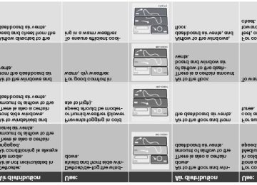
Information display
Messages
When an indicator or warning light in the instrument panel comes on, a message is also shown in the information display. To read a message:
1. Press the READ button (1).
2. Pressing READ repeatedly enables you to scroll to any other messages that may be stored.
NOTE
If a message is displayed when e.g. you are using the trip computer, this message must be read before you can access the trip computer
54 02 Instruments and controls
Information display
55 02 Instruments and controls
Lighting panel
Parking lights
The front and rear parking lights can be turned on even when the ignition is switched off.
Turn switch (1) to position
The license plate lights also illuminate when the parking lights are switched on.
Headlights
1. Turn the ignition key to position II.
2. The low beam headlights (daytime running lights) illuminate automatically, except when the light switch (1) is in position
1.
NOTE
See page 57 for information on switching between high and low beams.
1On Canadian models, the daytime running lights will remain on with the light switch in this position.
Brake lights
The brake lights come on automatically when the brakes are applied.
Fog lights
Front fog lights The front fog lights can be used in combination with either the headlights or the parking lights.
1. Turn the ignition to position II.
2. Press button (3) to turn on the front fog lights.
An indicator light in the button illuminates when the front fog lights are on.
Rear fog light The single rear fog light is located in the driver's side taillight cluster.
The rear fog light will only function in combination with the high/low beam headlights or the optional front fog lights.
1. Turn the ignition key to position II.
2. Press button (5) to turn on the rear fog light.
56 02 Instruments and controls
Lighting panel
An indicator light in the button illuminates when the rear fog light is on.
NOTE
The rear fog light is considerably brighter than the normal taillights and should be used only when conditions such as fog, rain, snow, smoke or dust reduce visibility for other vehicles to less than 500 ft. (150 meters).
Instrument panel lighting
The instrument panel lighting illuminates when the ignition is in position II and the light switch (1) is in either position
or
NOTE
To make it easier to read the odometer, trip odometer, clock, and ambient temperature, these gauges illuminate when the vehicle is unlocked and when the key has been removed from the ignition switch. The lighting will go out when the vehicle is locked.
Move the thumb wheel (2) up to increase brightness or down to decrease brightness.
Unlocking the fuel filler door
With the ignition switched off, press button (4) to unlock the fuel filler door. Please note that the fuel filler door will remain unlocked until the car begins to move forward.
An audible click will be heard when the fuel filler door re-locks.
Please refer to the following information for instructions on manually opening the fuel filler door.
Manually unlocking the fuel filler door
If it should be necessary to manually unlock the fuel filler door from the trunk, the power retractable hard top should be up.
1. Remove the panel covering the taillight housing on the right side of the trunk.
2. Pull the cord that is attached to a hook to pop open the fuel filler door.
When the fuel filler door has opened, return the cord to the hook and replace the taillight cover panel.
57 02 Instruments and controls
Left-side steering wheel lever
Lever positions
1. Turn signals, lane change position
2. Turn signals, position for normal turns
3. High beam flash
4. Toggle between high and low beams, Home Safe lighting
Turn signals
When turning
Move the lever as far up or down as possible (to position 2) to start the turn signals.
The turn signals will be cancelled automatically by the movement of the steering wheel, or the lever can be returned to its initial position by hand.
When changing lanes The driver can automatically flash the turn signals 3 times by:
Moving the turn signal lever up or down to position 1 and releasing it. Moving the lever up or down to position 2 and immediately back to its original position.
NOTE
This automatic flashing sequence can be interrupted by immediately moving the lever in the opposite direction. If the turn signal indicator flashes faster than normal, check for a burned-out turn signal bulb.
High/low beam headlights
Continuous high beams 1. Turn the ignition key to position II.
2. With the light switch (1) in position 4) to toggle between high and low beams.
High beam flash 1. Turn the ignition key to position II.
, (see page 55) pull the turn signal lever toward the steering wheel (position
2. Pull the turn signal lever to position 3. The high beams will remain on until the lever is released.
Home safe lighting When you leave your car at night, you can make use of the home safe lighting function to illuminate the area in front of the car.
1. Remove the key from the ignition switch.
2. Pull the direction indicator lever as far as possible towards the steering wheel (to position 4) and release it.
3. Exit the car and lock the doors.
The headlights and parking lights will illuminate and remain on for 301, 60 or 90 seconds. The time interval can be changed according to your preferences by using the Personal Settings function, see page 71 for more information.
1Factory setting
58 02 Instruments and controls
Trip computer
The trip computer stores information gathered from several systems in your car and has four menus (five on Canadian models) that can be shown in the information display.
MILES TO EMPTY TANK AVERAGE (average fuel consumption) INSTANTANEOUS (current fuel consumption) AVERAGE SPEED DSTC (see page 149 for detailed information. ACTUAL SPEED (current speed in m.p.h., Canadian models only)
NOTE
Warning messages from the car's monitoring systems will override the trip computer function.
If a warning message is shown in the information display while you are using the trip computer:
1. You must acknowledge the message by pressing the READ button (A).
2. Press button A again to return to the trip computer function.
Controls
The trip computer functions can be accessed by twisting INFO (B) one step at a time in either direction. Twisting a final time returns you to the original function.
Resetting AVERAGE (average fuel consumption) and AVERAGE SPEED can be reset.
1. Select one of these functions. 2. Press RESET (C).
Holding RESET for at least five seconds resets both functions at the same time.
MILES TO EMPTY TANK This function shows the approximate distance that can be driven on the fuel remaining in the tank. This calculation is based on average fuel consumption during the last 20 miles (30 km) of driving and the amount of fuel remaining in the tank when the reading was taken. When the driving distance on current fuel reserve is less than 12 miles (20 km), "---- " will be displayed in the information display.
AVERAGE This value indicates fuel consumption since the last time the trip computer was reset (by pressing RESET, button C). When the engine is switched off, information on fuel consumption is stored and remains in system memory until the
RESET (button C) is pressed again.
INSTANTANEOUS This value indicates the current fuel consumption, based on readings taken once per second. When the car is not moving, "----" will be displayed.
AVERAGE SPEED This value indicates average speed since the last time the trip computer was reset (by pressing RESET, button C). When the engine is switched off, information on average
59 02 Instruments and controls
Trip computer
speed is stored and remains in system memory until the RESET (button C) is pressed again.
ACTUAL SPEED (Canadian models only) This function provides the driver with an instantaneous conversion of the car's current speed from km/h to m.p.h.
NOTE
Trip computer readings may vary slightly depending on the circumference of the tires on the car, tire inflation, or driving style.
60 02 Instruments and controls
Right-side steering wheel lever
Windshield wipers
A. Windshield/headlight washers
B. Rain sensor (option) - on/off
C. Thumb wheel
Windshield wipers off
The windshield wipers are off when the lever is in position 0.
Manual wiper function
From position 0, move the lever upward. The windshield wipers will sweep one stroke at a time for as long as the lever is held up.
Intermittent wiper function
With the lever in this position, you can set the wiper interval by moving the thumb wheel (C) upward to increase wiper speed or downward to decrease the speed.
Continuous wiper function
The wipers operate at "normal" speed.
High speed wiper function.
A -Windshield washers
Pull the lever toward the steering wheel and release it. The wipers will make 2-3 sweeps across the windshield after the lever has been released.
CAUTION
Use ample washer fluid when washing the windshield. The windshield should be thoroughly wet when the wipers
Before using the wipers, ice and snow should be removed from the windshield. Be sure the wiper blades are not
are in operation.
frozen in place.
Headlight washers (certain models)
When the lever has been pulled, high pressure jets mounted in the bumper will spray the headlights.
The following applies to conserve washer fluid (see page 55 for information on the light switch positions):
Low/high beam headlights on
The headlights will be washed the first time the windshield is washed. Thereafter, the headlights will only be washed once for every five times the windshield is washed within a 10-minute period.
Parking lights on
Optional Bi-Xenon® headlights will be washed once for every five times the windshield is washed.
Normal halogen headlights will not be washed.
61 02 Instruments and controls
Right-side steering wheel lever
B - Rain sensor (option)
The rain sensor automatically regulates windshield wiper speed according to the amount of water on the windshield. The sensitivity of the rain sensor is adjusted by moving the thumb wheel (C in the illustration on the previous page) up (the wipers will sweep the windshield more frequently) or down (the wipers will sweep the windshield less frequently).
On/Off
To activate the rain sensor: 1. Switch on the ignition.
2. Put the windshield wiper lever in position 0.
3. Press button B (see the illustration on the previous page). The rain sensor symbol will appear in the lower display.
The rain sensor can be deactivated by:
Pressing button (B) with the ignition on.
or
Moving the windshield wiper lever down. If the lever is moved up, the rain sensor function will remain activated
CAUTION
The rain sensor should be deactivated when washing the car in an automatic car wash, etc. If the rain sensor function is left on, the wipers will start inadvertently in the car wash and could be damaged
The rain sensor is automatically deactivated:
When the key is removed from the ignition. Five minutes after the ignition is switched off if the key is left in the ignition.
C - Thumb wheel
The thumb wheel is used to set the wiper interval when intermittent wiping is selected, or the sensitivity to the amount of rain on the windshield when the rain sensor is selected. Move the wheel upward or downward to increase/decrease wiper speed when the intermittent function is selected, or to increase/decrease the optional rain sensor's sensitivity when the this function is activated
62 02 Instruments and controls
Cruise control
Engaging the cruise control function
The cruise control buttons are located on the left side of the steering wheel hub.
1. Press the CRUISE button. CRUISE will appear in the function display in the center of the instrument panel.
NOTE
This does not set the vehicle's speed.
2. Press + or - to set the current speed. CRUISE ON will be displayed.
Increasing or decreasing speed
Use + or - in the following ways to increase or decrease the vehicle's speed:
1. Press and hold down + or - until the vehicle reaches the desired speed. This will become the set speed when the button is released.
2. Press + or - for approximately a half second and release the button to increase or decrease vehicle speed by approximately 1 mph (1.6 km/h).
NOTE
Cruise control will not function at speeds below 20 mph. (30 km/h).
Momentary acceleration, for less than 1 minute (e.g. when passing another car), does not affect cruise control operation. The car will automatically return to the previously set speed when the accelerator pedal is released.
Temporarily disengaging the cruise control
Press 0 to temporarily disengage cruise control.
CRUISE will appear in the function display. The currently set speed is stored in the system's memory.
Cruise control is also automatically disengaged:
If the speed drops below approximately 20 mph (30 km/h) when driving uphill. When the brake or clutch pedal is depressed. If the gear selector is moved to position N. During wheel spin or wheel lock-up. If the vehicle's speed is increased by using the accelerator pedal for more than 1 minute.
63 02 Instruments and controls
Cruise control
Returning to the set speed
Press the button to resume the previously set speed.
Disengaging cruise control
Cruise control can also be disengaged by:
Pressing the CRUISE button (CRUISE ON will no longer be shown in the function display). Putting the gear selector in Neutral (N).
WARNING
Cruise control should not be used in heavy traffic or when driving on wet or slippery roads. Cruise control may not maintain set speed on steep downgrades.
64 02 Instruments and controls
Steering wheel adjustment, Hazard warning flashers
Steering wheel adjustment
Both the height and the reach of the steering wheel can be adjusted to a comfortable position for the driver.
1. Pull down the lever on the steering column to release the steering wheel.
2. Adjust the steering wheel to a suitable position
3. Press the lever back into place to lock the steering wheel in the new position. If necessary, press the steering wheel slightly while pressing the lever into the locked position.
Check that the steering wheel is locked in the new position.
WARNING
Never adjust the steering wheel while driving.
Hazard warning flashers
The four-way flasher should be used to indicate that the vehicle has become a traffic hazard. To activate the flashers, press the triangular button in the center dash. Press the button again to turn off the flashers.
NOTE
Regulations regarding the use of the hazard warning flasher may vary, depending on where you live. The hazard warning flashers will be activated automatically if an airbag deploys.
65 02 Instruments and controls
Parking brake
Parking brake (hand brake)
The parking brake lever is located between the front seats.
NOTE
The indicator light will light up even if the parking brake has only been partially applied.
When applying the parking brake 1. Press firmly on the brake pedal.
2. Pull the parking brake lever up firmly to its full extent.
3. Release the brake pedal and ensure that the vehicle is at a standstill.
4. If the vehicle rolls, the parking brake lever must be pulled more firmly.
5. When parking a vehicle always put the gear selector in first gear (for manual transmission) or P (for automatic transmission).
Parking on a hill
If the vehicle is pointing uphill, turn the front wheels so that they point away from the curb. If the vehicle is pointing downhill, turn the front wheels so that they point toward the curb.
Releasing the parking brake 1. Press firmly on the brake pedal.
2. Pull the lever up slightly, press the button at the end of the lever and lower the lever completely.
WARNING
Pull up the parking brake lever up firmly to its full extent.
66 02 Instruments and controls
12-volt sockets
12-volt socket (front seat)
The 12-volt socket can be used to plug in certain accessories such as cellular telephones, etc. The maximum current is
10A. The key must be in position I (or higher) for the auxiliary socket to function.
Ashtrays/cigarette lighter The auxiliary socket can also be used for a cigarette lighter 1, and ashtrays 1 are also available. Please contact your Volvo retailer.
1 Accessory.
NOTE
The cover should be kept on when the auxiliary socket is not in use.
Auxiliary equipment
The buttons to the left of the 12-volt socket can be used for Volvo-installed optional or auxiliary equipment.
67 02 Instruments and controls
Power windows
Operation
The power windows are opened and closed using the buttons in the armrests, or can be opened by pressing the unlock button on the central locking system's remote control (see page 113).
Opening/closing the windows from inside the car
NOTE
The ignition must be ON (ignition in position I, II or the engine running) for the power windows to function. The power windows will also function after the ignition has been switched off as long neither of the doors has been
opened.
Opening a window
Lightly press down the front edge of any of the buttons (2 or 3) to the first detent ("stop") to open a window to the
position of your choice.
WARNING
Always remove the ignition key when the vehicle is unattended. Never leave children unattended in the vehicle. Make sure that the windows are completely unobstructed before they are operated.
Press down the front part of one or both buttons 3 as far as possible and release to automatically open the front
window(s) completely.
To stop the window at any time, pull the button up.
NOTE
To reduce buffeting wind noise if the rear windows are opened, also open the front windows slightly.
Closing a window
Lightly pull up the front edge of any of the buttons (2 or 3) to the first detent ("stop") to close a window to the
Pull up the front part of one or both buttons 3 as far as possible and release to automatically close the front
position of your choice.
window(s) completely.
All windows Button 1 can be used to open or close all of the windows at the same time.
Briefly press the right side of the button to automatically open all of the windows. Press and hold down the left side of the button to close all of the windows.
68 02 Instruments and controls
Mirrors
Rearview mirror
Auto-dim function An optional integrated sensor reacts to headlights from following traffic and automatically reduces glare.
Rearview mirror with compass (option)
The upper right-hand corner of the rearview mirror has an integrated display that shows the compass direction toward which the car is pointing. Eight different directions can be displayed: N, NE, E, SE, S, SW, W and NW. The display shows your car's orientation with respect to true north.
Calibrating the compass
The compass may need to be calibrated in certain cases. If calibration is required, the character C appears in the mirror's display.
The earth is divided into 15 magnetic zones. The compass is initially set for the zone to which the car was delivered, and should always be adjusted if the car is driven to a new magnetic zone. A "C" will be displayed if calibration becomes necessary.
69 02 Instruments and controls
Mirrors
To calibrate the compass: 1. Stop the car in a large, open area, away from traffic.
2. Using a pen or similar object, hold the button (1) depressed for at least 6 seconds. "C" will be displayed.
3. Press button (1) for at least 3 seconds to display the number of the current magnetic zone.
4. Press button (1) repeatedly until the number for the required geographical area (1-15) is displayed. "C" will be displayed again.
5. Drive slowly in a circle at a maximum speed of 6 m.p.h. (10 km/h) until a compass direction is displayed.
Calibration is complete.
Magnetic zones
70 02 Instruments and controls
Mirrors
Power door mirrors
The mirror control switches are located on the driver's door armrest.
To adjust the mirrors:
Driver's door mirror: Press the L button (a light in the switch will go on) to activate the adjustment control. Use this control to adjust the driver's door mirror.
Passenger's door mirror: Press the R switch (a light in the switch will go on) to activate the adjustment control. Use this control to adjust the passenger's door mirror.
After you have adjusted the mirror(s), press the L or R switch again (the LED will go out) to deactivate the adjustment control.
WARNING
The mirrors should always be adjusted prior to driving. Objects seen in the passenger's side wide-angle door mirror are closer than they appear to be.
Storing the mirrors' position The position of the power door mirrors is stored when the car is locked with the remote control. When the car is unlocked with the same remote control, the mirrors will move to the stored position.
Blind Spot Information System (BLIS) -option The Blind Spot Information System (BLIS) is an information system that indicates the presence of another vehicle in the side-view mirror's "blind area." See page 159 for detailed information.
71 02 Instruments and controls
Personal settings
Control panel
A. Display
B. Menu button
C. Exit button
D. Enter button
E. Menu navigation controls
Personal settings can be made for some of the car's functions, such as the central locking system, climate control, and the audio system. Please refer to page 236 for more information on the audio functions that can be adjusted. The settings are presented in the display (A).
To access the menu and adjust settings: 1. Press MENU (B).
2. Scroll to "Car Settings" using the menu navigation control (E).
3. Press ENTER (D).
4. Select an alternative using the menu navigation control (E).
5. Confirm your selection by pressing ENTER.
To exit the menu:
Press EXIT (C).
Available settings
Clock adjust To set the time:
1. Use the number keys or the up/down arrow keys on the navigation control (E) to change the hour or minute.
2. Select hour(s) or minute(s) to be changed with the left/right arrow keys.
3. Press ENTER to start the clock.
NOTE
If you are currently using the 12-hour time setting, use the up/down arrow keys to select AM/PM after the minute- setting has been adjusted.
Lock confirmation light When the car is locked/unlocked with the remote control, the direction indicators can be selected to flash to confirm the action. The alternatives On/Off are available for both locking and unlocking.
72 02 Instruments and controls
Personal settings
Autolock When the car starts to move, the doors and trunk can be locked automatically. The alternatives On/Off are available.
NOTE
Pulling the handle twice on a door unlocks and opens that door.
Unlock There are two alternatives for unlocking:
Global (All doors)
Unlocks all doors and the trunk with one press on the remote control.
Two Step (Two-stage unlocking)
This alternative unlocks the driver's door with one press on the remote control. A second press unlocks the passenger's door and the trunk.
Operating side windows The following alternative can be selected for opening all windows at the same time by pressing and holding the Unlock button on the central locking system's remote control. See page 113 for more information.
Auto open all windows On/Off
Approach lighting This alternative determines the length of time for which the car's lights will remain on when the Approach light button on the central locking system's remote control is pressed. Intervals of 30/60/90 seconds may be selected. See page 113
for more information.Home safe lighting This alternative determines the length of time for which the car's lights will remain on when the high beam lever on the steering column is pulled toward the wheel with the ignition switched off. Intervals of 30/60/90 seconds may be selected. See page 57 for information on using this function.
Information
VIN number:
The VIN (Vehicle Identification Number) is the car's unique identity number.
Number of Keys:
The number of keys registered for the car is displayed here.
Climate functions
Blower speed in AUTO mode:
The blower speed can be set to AUTO mode in models equipped with ECC. Choose between "Low", "Normal" and "High".
Timer for recirculation:
When the timer is active, the air recirculates in the car for 3-12 minutes depending on the ambient temperature. Select On/Off depending on whether the recirculation timer is to be active or not.
Reset to factory settings Use this alternative to return to the default climate system settings.
73 02 Instruments and controls
HomeLink® Universal Transceiver (option)
Introduction
HomeLink1 is a system that can be programmed to learn the codes of three different remote controlled-devices (for example, a garage door opener, remote lighting, entry gate). HomeLink's sun visor-mounted transceiver, powered by your car's electrical system, may then be used in place of your handheld remote controls. The HomeLink transceiver consists of three programmable buttons and an indicator light.
1HomeLink is a registered trademark of Johnson Controls, Intl.
© JCI, All rights reserved
NOTE
For your security, the HomeLink Universal Transceiver is designed to not function if you lock your car from the
outside.
vehicle.
Retain the original transmitter(s) for future programming procedures (for example, if you purchase a new vehicle). For your own security, erase all programmed buttons on the HomeLink Universal Transceiver when you sell your
Metallic sun protection films should not be used on any windows in a vehicle equipped with HomeLink Universal
Transceiver. This could interfere with the transceivers function.
Operating the HomeLink Universal Transceiver Once programmed, the HomeLink Universal Transceiver can be used in place of your handheld transmitters.
NOTE
The HomeLink universal transceiver will function for 30 minutes after the driver's door has been opened without switching on the vehicle's ignition.
Press the programmed HomeLink button to activate the garage door, driveway gate, security lightning, home security system etc. Your original hand-held transmitters may, of course, be used at any time.
WARNING
If you use HomeLink to open a garage door or gate, be sure no one is near the gate or door while it is in motion. Do not use the HomeLink Universal Transceiver with any garage door opener that lacks safety "stop" and
"reverse" features as required by federal safety standards. (This includes any garage door opener model manufactured before April 1, 1982). A garage door opener that cannot "detect" an object, signalling the door to "stop" and "reverse" does not meet current federal safety standards. Using a garage door opener without these features increases the risk of serious injury or death. For more information on this matter, call toll-free 1-800-355-3515. (Internet: www.HomeLink.com).
Programming the transceiver for the first time (U.S. residents) 1. For first time training, press and hold the two outer HomeLink buttons, releasing only when the HomeLink indicator light begins to flash after 20 seconds. (Do not perform this step when training the additional HomeLink buttons.)
2. Position the hand-held transmitter 1-3 inches away from the HomeLink surface
74 02 Instruments and controls
HomeLink® Universal Transceiver (option)
(located on your sun visor), keeping the HomeLink indicator light in view.
3. Using both hands, simultaneously press and hold both the desired HomeLink button and hand held transmitter button. DO NOT release until the HomeLink indicator light flashes slowly and then rapidly. When the indicator light flashes rapidly, both buttons may be released. (The rapid flashing indicates successful training.)
NOTE
Some garage door openers may require you to replace step 3 with the "cycling" procedure noted in the "Programming the transceiver for the first time (Canadian residents)" section.
4. Press and hold the trained HomeLink button and observe the indicator light.
If the indicator light is solid/continuous, training is complete and your device should activate when the HomeLink
button is pressed and released.
If the indicator light blinks rapidly for 2 seconds and then turns a solid/continuous light, proceed with the following
training instructions for a rolling code device. A second person may make the following steps quicker and easier. Please use a ladder or other device. Do not stand on your vehicle to perform the next steps.
5. At the garage door opener receiver (motorhead unit) in the garage, locate the "learn" or "smart" button (usually near where the hanging antenna wire is attached to the unit). If there is difficulty locating the training button, reference the garage door opener's manual or contact us toll-free 1-800-355-3515 (Internet: www.HomeLink.com).
6. Press and release the "learn" or "smart" button (the name and color of the button may vary by manufacturer).
NOTE
Once the button is pressed, there are 30 seconds in which to initiate the next step.
7. Return to the vehicle and firmly press and hold the trained HomeLink button for two seconds and release. Repeat the "press/hold/release" sequence up to 3 times to complete the training process.
To train additional HomeLink buttons, begin with step two.
Programming the transceiver for the first time (Canadian residents) 1. For first time training, press and hold the two outer HomeLink buttons releasing only when the HomeLink indicator light begins to flash after 20 seconds. (Do not perform this step when training the additional HomeLink buttons.)
2. Position the hand-held transmitter 1-3 inches (2.5-7.5 cm) away from the HomeLink surface (located on your) keeping the HomeLink indicator light in view.
3. Using both hands, simultaneously press and hold both the desired HomeLink button and hand held transmitter button. During programming, your handheld transmitter may automatically stop transmitting. Continue to press and
hold the desired HomeLink button while you press and re-press ("cycle") your handheld transmitter every two seconds until the frequency signal has been learned. The indicator light will flash slowly and then rapidly after several seconds upon successful training. DO NOT release until the HomeLink indicator light flashes slowly and then rapidly. When the indicator light flashes rapidly, both buttons may be released. (The rapid flashing indicates successful training.)
75 02 Instruments and controls
HomeLink® Universal Transceiver (option)
4. Press and hold the trained HomeLink button and observe the indicator light.
If the indicator light is solid/continuous, training is complete and your device should activate when the HomeLink
button is pressed and released.
If the indicator light blinks rapidly for 2 seconds and then turns a solid/continuous light, proceed with the following
training instructions for a rolling code device. A second person may make the following steps quicker and easier. Please use a ladder or other device. Do not stand on your vehicle to perform the next steps.
5. At the garage door opener receiver (motorhead unit) in the garage, locate the "learn" or "smart" button (usually near where the hanging antenna wire is attached to the unit). If there is difficulty locating the training button reference the garage door opener's manual or contact us.
6. Press and release the "learn" or "smart" button (the name and color of the button may vary by manufacturer).
NOTE
Once the button is pressed, there are 30 seconds in which to initiate the next step.
7. Return to the vehicle and firmly press and hold the trained HomeLink button for two seconds and release. Repeat the "press/hold/release" sequence up to 3 times to complete the training process.
NOTE
During programming, your hand-held transmitter may automatically stop transmitting. Continue to press and hold the desired HomeLink button while you press and repress ("cycle") your hand-held transmitter every two seconds until the frequency signal has been learned. The indicator light will flash slowly and then rapidly after several seconds upon successful training. If necessary, follow steps 5-7 to complete the training for a rolling code device.
To train additional HomeLink buttons, begin with step two.
Rolling Code Programming Rolling code garage door openers that are "code-protected" and manufactured after 1996 may be determined by the- following:
Reference the garage door opener owner's manual for verification. The handheld transmitter appears to program the HomeLink Universal Transceiver but does not activate the garage
door.
Press and hold the trained HomeLink button. The garage door opener has the rolling code feature if the indicator
light flashes rapidly and then turns solid after 2 seconds.
To train a garage door with the rolling code feature, follow these instructions (the aid of a second person may make the training quicker and easier):
1. Locate the training button on the garage door opener motor head unit. Exact location and color of the button may vary by garage door opener brand. If there is difficulty locating the training button, reference the garage door opener owner's manual or please visit our Web site at www.homelink.com.
2. Press the training button on the garage door opener motor head unit (which activates the "training light").
NOTE
Following step 2, there are 30 seconds in which to initiate step 3.
3. Firmly press and release the programmed HomeLink® button. Press and release the HomeLink button a second time to complete the training process. (Some garage door openers may require
76 02 Instruments and controls
HomeLink® Universal Transceiver (option)
you to do this procedure a third time to complete the training.)
The garage door opener should now recognize the HomeLink Wireless Control System. The remaining two buttons may now be trained if this has not previously been done. Refer to the Programming portion of this text. The HomeLink Wireless Control System (once programmed) or the original handheld transmitter may be used to activate the garage door. In the event that there are still difficulties in programming the HomeLink Wireless Control System, please visit our Web site, www.homelink.com.
Reprogramming a Single HomeLink Button To program a device to HomeLink using a HomeLink button previously trained, follow these steps:
1. Press and hold the desired HomeLink button. Do NOT release until step 4 has been completed.
2. When the indicator light begins to flash slowly ( after 20 seconds), position the handheld transmitter 1 to 3 inches away from the HomeLink surface.
3. Press and hold the handheld transmitter button. The HomeLink indicator light will flash, first slowly and then rapidly.
4. When the indicator light begins to flash rapidly, release both buttons.
The previous device has now been erased and the new device can be activated by pushing the HomeLink button that has just been programmed. This procedure will not affect any other programmed HomeLink.
Erasing Channels Individual buttons cannot be erased. However, to erase all three programmed buttons:
1. Press and hold the two outside buttons until the indicator light begins to flash (after 20 seconds).
2. Release both buttons.
The HomeLink® Wireless Control System is now in the training (learning) mode and can be programmed at any time following steps 2 through 4 in the Programming section.
77 02 Instruments and controls
This page left intentionally blank.
Contents | Top of Page
2 0 0 8
VOLVOC70
78 03 Climate
80
General information Air vents 81
Electronic Climate Control (ECC) 82
Air distribution 8679 03 Climate
80 03 Climate
General information
Air conditioning - A/C
Your car is equipped with an Electronic Climate Control (ECC).
The air conditioning system can be switched off, but for optimal air quality in the passenger compartment and to prevent the windows from fogging, the air conditioning should be left on - even in cool weather.
NOTE
In warm weather, a small amount of water may accumulate under the car when it has been parked. This water is condensation from the A/C system and is normal.
Ice and snow
Always keep the air intake grille at the base of the windshield free of snow.
Fog on the inside of the windows
The defroster function should be used to remove fog or mist from the inside of the windows. Keeping the windows clean with a commercially available window washing spray will also help prevent fogging or misting.
Climate control maintenance
Special tools and equipment are required to maintain and carry out repairs on the climate system. Work of this type should only be done by a trained and qualified Volvo service technician.
Refrigerant
Volvo cares about the environment. The air conditioning system in your car contains a CFC-free refrigerant - R134a. This substance will not deplete the ozone layer. The system contains 1.2 lbs (530 g) R134a (HFC 134a), and uses PAG oil.
Passenger compartment filter
Replace the cabin air filter with a new one at the recommended intervals. Please refer to your Warranty and Service Records Information booklet, or consult a trained and qualified Volvo service technician for these intervals. The filter should be replaced more often when driving under dirty and dusty conditions. The filter cannot be cleaned and therefore should always be replaced with a new one.
NOTE
There are different types of cabin air filters. Ensure that the correct type is installed.
Display
The display above the climate control panel shows the climate settings that have been made.
Personal settings
There are two functions in the climate system that can be set to your preferences:
Blower speed to Auto mode (models with ECC only). Timer controlled recirculation of the air in the passenger compartment.
For information about how to make these settings, see the Personal settings section on page 71.
81 03 Climate
Air vents
Air vents in the dashboard
A. Open
B. Closed
C. Horizontal air flow
D. Vertical air flow
Direct the outer air vents toward the side windows to defrost.
82 03 Climate
Electronic Climate Control (ECC)
1. Auto - On/Off
2. Blower speed
3. Recirculation
4. Defroster
5. Airflow controls
6. A/C - ON/OFF
7. Heated driver's seat
8. Heated front passenger's seat
9. Rear window and door mirror defrosters
10. Temperature selector
NOTE
The sunlight sensor on the upper side of the dashboard and the passenger compartment temperature sensor, located
behind the climate system control panel, should not be obstructed.
The air conditioning system is temporarily switched off during full throttle acceleration.
ECC functions
1. Auto - On/Off
The AUTO function automatically regulates climate control to maintain the desired temperature. The automatic function controls heating, air conditioning, blower speed, recirculation, and air distribution.
If you select one or more manual functions, the remaining functions continue to be controlled automatically. All manual settings are
83 03 Climate
Electronic Climate Control (ECC)
switched off when AUTO is switched on. AUTO CLIMATE is shown in the display.
2. Blower speed
The blower speed can be increased or decreased by turning the knob. The blower speed is regulated automatically if AUTO is selected. The previously set blower speed is disconnected.
NOTE
If the knob is turned counterclockwise and the blower indication in the display goes out, the blower and the air conditioning are switched off. The display shows the blower symbol and OFF.
3. Recirculation
This function can be used to shut out exhaust fumes, smoke, etc from the passenger compartment. The air in the passenger compartment is then recirculated, i.e. no air from outside the car is taken into the car when this function is activated.
If the air in the car recirculates for too long, there is a risk of condensation forming on the insides of the windows,
especially in winter.
Timer The timer function minimizes the risk of fogging, or stale air when the recirculation function is selected. See page 72
for information on setting the recirculation timer.NOTE
Recirculation is always disengaged if the defroster button is engaged to clear ice or condensation from the side windows.
4. Defroster
Directs airflow to the windshield and side windows and increases blower speed.
When the defroster is activated:
Air flows to the windows at high blower speed. The LED in the defroster button lights up when this function is activated. The air conditioning system is controlled
to provide maximum air dehumidification.
The air conditioning is automatically switched on (can be switched off by pressing button 5).
The air is not recirculated.
5. Airflow controls
Press one of the three buttons in the illustration to activate the selected airflow. A symbol in the display above the climate control panel and a lit LED in the selected button indicate that the manual function has been selected. With manually selected airflow both warm and cool air can be selected. See also the table on page 86.
6. Air conditioning On/Off
ON: The air conditioning system is engaged when the ON light is lit and is controlled automatically by the system to maintain the selected temperature.
OFF: The system is disengaged when the OFF lights up
When OFF is selected and the OFF LED is lit, the air conditioning system is deactivated.
84 03 Climate
Electronic Climate Control (ECC)
Other functions are still controlled automatically.
When Defroster (4) is selected, the air conditioning system is activated for maximum dehumidifying.
7 and 8. Heated front seats (option)
Maximum heating: Press the button once - both LEDs light up.
Reduced heating: Press the button a second time - one LED lights up.
Seat heating off: Press the button a third time - no LEDs are lit.
9. Rear window and door mirror defrosters
Press to defrost the rear window and door mirrors.
The rear window and door mirrors are defrosted simultaneously if the switch is pressed once. The defrost function is active if the LED in the switch is illuminated.
The function can be switched off manually by pressing the button. The defrost function switches off automatically after 12-20 minutes, depending on the outside temperature.
NOTE
This function is automatically switched off when the power retractable hard top is down. On certain markets, the defrost function may remain on longer than 20 minutes in cold weather to help keep the
rear window free from ice or condensation.
10. Temperature selector
The temperatures on the driver's and passenger's sides can be set separately using the knob (with the thermometer in it). The temperature can be set for both sides of the car when the ignition is switched on (both LEDs will be on), which means that a temperature setting will apply to both sides of the car.
To set the temperature on one side of the car:
Press the knob once. The LED for one side of the car will light up. Turn the knob to adjust the temperature. Press the knob a second time to set the temperature on the opposite side of the car. Press the knob a third time to set the temperature on both sides of the car at the same time.
NOTE
Selecting a temperature that is higher or lower than necessary will not heat or cool the passenger compartment faster.
85 03 Climate
Electronic Climate Control (ECC)
ECC sensors
The sunlight sensor is on the upper side of the dashboard
The passenger compartment temperature sensor is located behind the climate system control panel. The ambient temperature sensor is in the driver's side door mirror. The humidity sensor is in the rearview mirror.
These sensors should never be obstructed.
NOTE
The sunlight sensor monitors the side of the vehicle from which the sun shines into the passenger compartment. This means that the temperature may differ slightly between the left and right air vents, even if the climate system temperature is set to be the same for both sides of the passenger compartment.
86 03 Climate
Air distribution
87 03 Climate
This page left intentionally blank.
Contents | Top of Page
2 0 0 8
VOLVOC70
88 04 Interior
Front seats 90
Power retractable hard top 94
100
Interior lighting Storage compartments 102
107
Trunk89 04 Interior
90 04 Interior
Front seats
Manual seat adjustment
The driver's and passenger's seats can be adjusted in a number of ways to provide a comfortable driving and sitting position.
1. Forward-rearward: Pull the lever up and slide the seat to the position of your choice.
2. Use this control to raise or lower the front edge of the seat cushion.
3. Use this control to raise or lower the rear edge of the seat cushion.
4. Turn this knob (option on some passenger's seats) to adjust the firmness of the lumbar support1.
5. Turn this knob to adjust the backrest tilt.
6. Control panel for power seats.
WARNING
Do not adjust the seat while driving. Adjust the driver's seat and seat belt (see page 14) before driving. The seat should be adjusted so that the brake
pedal can be depressed fully.
Position the seat as far rearward as comfort and control allow.
1Also applies to the optional power seat.
91 04 Interior
Front seats
Accessing the rear seat
Seat access buttons (power seat shown)
Manual seat Moving the seat forward:
1. Remove the seat belt from its guide (see page 15).
2. Pull up control 1 (see the illustration), hold it up, and fold the backrest forward until it locks in position.
3. Slide the seat forward.
Moving the seat rearward:
1. With the backrest folded forward in the locked position, slide the seat rearward to its original position.
2. Pull up control 1, hold it up, and fold up the backrest to the upright position.
3. Return the seat belt to its guide.
Power seats Easy entry is only intended to be used when the front seat in unoccupied.
Moving the seat forward:
1. Remove the seat belt from its guide (see page 15).
2. Pull up control 1, hold it up, and fold the backrest forward until it locks in position.
3. Press and hold button 2 while the seat moves forward.
Moving the seat rearward:
1. With the backrest folded forward in the locked position, press and hold down button 2 until the seat has returned to its original position.
2. Pull up control 1, hold it up, and fold up the backrest to the upright position.
3. Return the seat belt to its guide.
WARNING
After the seat has been returned to its original position, be sure that the backrest is securely locked in the upright position.
92 04 Interior
Front seats
Power seats (option)
The power driver's seat can be adjusted:
If the ignition key is in position I or II. During a 10 minute period after the doors have been unlocked if the door remains open. If the door is closed and the ignition key is not yet in the ignition, or if the key is in position 0, the seat can be
adjusted or during a period of 40 seconds. The power passenger's seat can only be adjusted if the ignition key is in position I or II, or if the engine is running.
Adjusting the seat Seat adjustment controls 1, 2, 3, and 4 on the side of the seat can be used to move the seat to the position of your choice.
1. Move this section of the control up or down to raise/lower the front section of the seat cushion.
2. Move the control forward/rearward to move the seat forward or rearward.
3. Move this section of the control up or down to raise/lower the rear section of the seat cushion.
4. Backrest tilt.
NOTE
The power seats have an overload protector that activates if a seat is blocked by any object. If this occurs, switch off the ignition (key in position 0) and wait for approximately 20 seconds before operating the seat again.
Emergency stop If the seat inadvertently begins to move, press any of the buttons to stop the seat.
Programming the seat memory, driver's seat only (option)
Three different seating positions (and the position of the door mirrors) can be stored in the seat's memory. The memory buttons are located on the outboard side of the driver's seat (see the illustration). The following example explains how memory button 1 can be programmed. Buttons 2 and 3 can be programmed in the same way.
To program (store) a seat position in memory button 1:
1. Adjust the seat (and door mirrors) to the desired position (see the instructions under "Adjusting the seat").
93 04 Interior
Front seats
2. Press and hold down the "M" (Memory) button.
3. With the "M" button depressed, press memory button 1 to store the seat's current position.
To move the seat to the position that it was in when memory button 1 was programmed, press and hold down button 1
until the seat stops moving.As a safety precaution, the seat will stop automatically if the button is released before the seat has reached the preset position.
Central locking system remote control and driver's seat memory The remote control transmitter can also be equipped with an optional function that controls the electrically operated driver's seat and door mirrors in the following way:
1. Adjust the seat and door mirrors to the desired position.
2. When you leave the car, lock it using the remote control.
3. The next time the driver's door is unlocked with the same remote control and that door is opened within 2 minutes, the driver's seat and door mirrors will automatically move to the position that they were in when the doors were most recently locked with the same remote control.
NOTE
The memory function in the remote control operates independently of the memory function in the seat.
WARNING
Because the driver's seat can be adjusted with the ignition off, children should never be left unattended in the car. Movement of the seat can be STOPPED at any time by pressing any button on the power seat control panel. Do not adjust the seat while driving. The seat should be adjusted so that the brake pedal can be depressed fully. In
addition, position the seat as far rearward as comfort and control allow.
The seat rails on the floor must not be obstructed in any way when the seat is in motion.
94 04 Interior
Power retractable hard top
Before raising and lowering the power retractable hard top
Please observe the following information before operating the power retractable hard top:
There should be no objects on the power retractable hard top's cover. Remove all snow, ice or loose objects from the power retractable hard top and trunk lid. The top should be dry before it is lowered.
CAUTION
If the power retractable hard top is lowered while it is wet, water may drip into the passenger compartment or trunk
There should be at least 6.5 feet (2 meters) of free space from the ground (distance A in the illustration). There should be at least 8 inches (20 cm) of free space behind the vehicle (distance B in the illustration in the center
column).
The ambient temperature should be above 14°F (-10°C). The trunk divider (see page 95) must be closed. The trunk must be closed. The vehicle must be at a standstill and the brake pedal must be pressed.
Volvo also recommends the following:
The vehicle should be parked outdoors, on level ground. Raising or lowering the power retractable hard top should preferably be done in one, continuous operation. If the vehicle is parked outdoors, the engine should be idling to help avoid battery drain.
CAUTION
If the instructions on these pages are not followed, damage to the power retractable hard top's mechanism may occur.
WARNING
The power retractable hard top must not be obstructed in any way when it is being operated. Always have an unobstructed view of the power retractable hard top when it is in motion. See also the decal on the trunk divider.
Anyone near the vehicle should be well clear of the power retractable hard top's moving parts before it is operated. Children must never be allowed to play with the power retractable hard top control buttons. Do not leave the power retractable hard top motionless longer than necessary while it is being operated Do not leave the key in the ignition if there are children in the vehicle.
95 04 Interior
Power retractable hard top
Trunk divider
The purpose of the trunk divider is to indicate the amount of cargo that can be stowed in the trunk without affecting movement of the power retractable hard top.
To open, grasp the handle and lift.
To close, pull the trunk divider rearward.
Be sure to close the trunk divider completely so that it locks in place on both the right and left sides.
NOTE
If the trunk divider is not completely closed, it will not be possible to operate the power retractable hard top.
Power retractable hard top cover
When lowered, the power retractable hard top is concealed by a cover, see the illustration above.
CAUTION
Do not sit or place heavy objects on the power retractable hard top cover.
96 04 Interior
Power retractable hard top
Raising or lowering the power retractable hard top
1. Turn the ignition key to position II, or start the engine if the vehicle is parked outdoors.
2. Press the brake pedal.
3. Press and hold down the left button (1) to raise the power retractable hard top or the right button (2) to lower it. Hold down the respective button until the top is completely raised or lowered. Release the button when an audible signal sounds. The message ROOF OPEN or ROOF CLOSED will be displayed.
CAUTION
Please heed any messages that may appear in the information display while the top is in operation. Any windows that are closed will be opened approximately 4 inches (10 cm) while the power retractable hard top
is in operation. The windows will be automatically re-closed when the top is completely raised or lowered.
WARNING
See the section "Before raising or lowering the power retractable hard top" on page 94 before operating the power
retractable hard top.
Never pull the release wire for the power retractable hard top's hydraulic system that is located under the rear seat
cushion. This wire is only intended for use by qualified service personnel. Pulling this wire could lead to:
High risk of being injured by the power retractable hard top mechanism. Unexpected movement of the hard top, or the hard top or the trunk could inadvertently open. The retractable hard top can be damaged.
Power retractable hard top-related text messages
PRESS BRAKE TO OPERATE ROOF
Press the brake pedal to operate the retractable hard top.
CLOSE TRUNK FOR ROOF OPERATION
CLOSE TRUNK SEP. FOR ROOF OPERAT
The trunk divider (see page 95 for more
The trunk is open and must be closed before operating the power retractable hard top.
97 04 Interior
Power retractable hard top
information) must be closed before operating the power retractable hard top.
LOW BATTERY FOR ROOF OPERATION
The battery's charge is too low to operate the power retractable hard top. In this case, the top can only be raised. Start the engine, or if necessary, have the battery charged before operating the top.
ROOF NOT LOCKED
The power retractable hard top is not fully up or down. Press and hold down the respective button again to complete the operation.
TEMP LIMITS ROOF OPERATION
The power retractable hard top mechanism has overheated, or the ambient temperature is below 14¡ F (-10¡ C). If the mechanism has overheated, wait for approximately 5 minutes (the message in the information display will disappear) and try to lower or raise the top again.
If a fault in the power retractable hard top mechanism occurs, the following messages will be displayed:
ROOF FAILURE SERVICE REQUIRED
The power retractable hard top cannot be operated. Contact an authorized Volvo retailer or service technician. If the top is down in this situation, a cover for the vehicle is provided in the trunk. See page 98 for more information.
ROOF FAILURE SEE MANUAL
The power retractable hard top must be operated according to the following instructions.
Emergency operation If the message ROOF FAILURE SEE MANUAL is displayed, the power retractable hard top cannot be operated in the normal way.
NOTE
If a fault has occurred and the power retractable hard top has been raised, it cannot be lowered again until the fault has been corrected.
CAUTION
Carefully read the information under "Before raising or lowering the power retractable hard top" on page 94 before operating the power retractable hard top. Damage may be unavoidable if the power retractable hard top must be operated under such conditions.
1. Press button 1 or 2 (see the illustration on page 96) until ROOF FAILURE SEE MANUAL is displayed.
2. Release the button.
3. Press the button again and hold it down. After approximately 5 seconds, the power retractable hard top will begin to move. Keep the button depressed until the top is fully raised.
NOTE
Movement of the top may stop briefly. However, the button should be held down throughout the entire operation. An audible signal will sound during the entire operation.
WARNING
Never pull the release wire for the power retractable hard top's hydraulic system that is located under the rear seat
cushion. This wire is only intended for use by qualified service personnel. Pulling this wire could lead to:
High risk of being injured by the power retractable hard top's opening/closing mechanism. Unexpected movement of the hard top/the hard top or the trunk could inadvertently open. The retractable hard top can be damaged.
98 04 Interior
Power retractable hard top
Temporary cover
The cover should only be used if the power retractable hard top is down and cannot be raised. It should be placed over the car so that the shock-cord attaching points are on the underside.
To install the cover 1. Raise all windows.
2. Take out the cover (stowed in the compartment in the rear side of the ski hatch in the center of the rear seat backrest), remove it from the bag and unfold it.
3. Slide the openings in the cover (3) over the respective door mirrors and attach the front shock-cord hooks (2) on the edges of the front wheel housings.
4. Slide the cover under the windshield wipers so that there is one fold under each wiper blade (1).
5. Guide the antenna through hole 5.
6. Attach the rear side hooks (4) on the edges of the rear wheel housings.
7. Attach the rear hooks (6) under the rear bumper.
99 04 Interior
Power retractable hard top
Wind blocker
The wind blocker is intended for use while driving with the power retractable hard top down to help reduce swirling breezes in the passenger compartment.
Installing the wind blocker 1. Unfold the wind blocker to its full width.
2. Unfold the supports on both rear sides.
3. Slide the winder blocker's rear supports under the rear head restraints so that they rest on the upper edge of the
backrest.
4. Press the side lock tabs into the holes in the side panels until they click into place.
5. Raise the wind blocker.
The zipper in the wind blocker can be opened to place or access objects in the rear seat.
CAUTION
Slide in the supports carefully to avoid damaging the upholstery.
WARNING
Make sure the wind blocker is securely attached. An improperly secured wind blocker may cause injury to
occupants of the vehicle or to other motorists.
No one should be allowed to sit in the rear seat when the wind blocker is in place.
When not in use, the wind blocker should be stored in its bag, in the trunk, against the rear seat backrest.
100 04 Interior
Interior lighting
Interior lighting
1. Driver's side reading light
2. Courtesy lighting
3. Passenger's side reading light
The front seat reading lights can be switched on and off by pressing buttons 1 or 3.
The courtesy lighting (2) can be set to three positions: Off - Press the right side of the button. Neutral position - the interior courtesy lighting comes on when a door is opened, and is switched off when the door
is closed.
ON - Press the left side of the button.
Rear seat reading lights
The rear reading lights can be switched on or off by pressing the respective buttons.
Courtesy lighting - automatic function
The interior lighting has a built-in automatic function that switches on the courtesy lighting for 30 seconds when:
the car is unlocked from the outside using the key or remote control the engine is switched off and the ignition key is turned to the 0 position.
The courtesy lighting lights up or remains on for 5 minutes when:
one of the doors is opened and left open. the courtesy lighting has not been switched off (the right side of button 2 depressed).
The automatic lighting goes out when:
the engine is started the car is locked from the outside using the key or remote control.
If the courtesy lighting is not switched off manually, it will be turned off automatically 5 minutes after the engine has been switched off.
101 04 Interior
Interior lighting
Vanity mirror
Raise the cover to switch on the light.
102 04 Interior
Storage compartments
103 04 Interior
Storage compartments
1. Lockable storage compartment in door
2. Jacket hanger (intended for light garments only)
3. Storage pocket on front side of front seat cushion
4. Glove compartment
5. Cup holders
6. Storage compartment in center console (for e.g. CDs)
7. Cup holders
8. Storage compartments in rear side panels
9. Storage compartment on rear side of front seat backrests.
WARNING
Anchor any heavy objects to prevent them from moving during sudden stops. Packages on the rear parcel shelf can obscure vision and may become dangerous projectiles in the event of a
sudden stop or an accident.
Glove compartment
The owners manual and maps can be stored here. There are also holders for coins, pens and fuel cards. The glove compartment can only be locked and unlocked using the detachable key blade from the central locking system's remote control. See page 115 for information on removing the key blade from the remote control, and page 124 for information on locking the glove compartment
Compartment in door panel
Open the compartment by lifting the front lower section of the lid.
Close by pressing the upper edge of the lid.
Locking function The door panel compartments can be locked by pressing the Lock button on the central locking system's remote control.
104 04 Interior
Storage compartments
Rear seat storage compartment
To open, press on the top center of the panel. Both the forward and rearward catches should release and the panel should spring open. If one side does not open, press again directly over that catch.
CAUTION
Never pull the panel; the catches may be damaged.
Press to close and latch the panel.
Jacket hanger
The jacket hanger is located on the inboard side of the front passenger's seat head restraint. It is only intended for hanging light garments.
105 04 Interior
Storage compartments
Storage under the front, center armrest
There are two storage compartments under the front, center armrest.
Press the smaller button on the front edge of the armrest and lift the armrest cover to access a shallow storage
compartment.
Press the larger button and lift the entire armrest to access a deeper compartment.
The deep storage compartment has room for 10 CD jewel cases. These cases must be inserted with their spines upward in order to allow space for 10 cases in the storage compartment.
Cup holders in the center console
Two cup holders are located under the sliding cover in the center console.
The cup holders can be lifted out if necessary. To do so, grasp the indentation on the rear edge of the cup holder and lift.
To put the cup holder back in place:
1. Slide the two locating tabs in the front side of the cup holder into the two corresponding recesses in the center console storage space.
2. Press down the rear edge of the cup holder.
To close the sliding cover, grasp the underside of the front edge and pull.
106 04 Interior
Storage compartments
Storage compartment behind the parking brake
If the buttons for optional equipment are not installed, the recess behind the parking brake can be used as a storage compartment.
107 04 Interior
Storage compartments
Loading the trunk
Loading the trunk with the power retractable hard top down When the power retractable hard top is down, it is folded in the trunk. Using the button shown in the illustration above, the folded power retractable hard top can be moved up or down slightly to facilitate loading or unloading small objects.
NOTE
This movement is part of the normal power retractable hard top operation, which means that messages pertaining to the power retractable hard top's operation (see page 96) also apply to the this function.
WARNING
Anyone near the vehicle should be well clear of the power retractable hard top's moving parts before it is operated.
CAUTION
Any objects that impede the movement of the power retractable hard top may damage the top or its mechanism. When the power retractable hard top has been raised for loading the trunk, or if its movement has been interrupted by pressing the button twice, the trunk should not be closed. Doing so can damage the system or cause paint damage.
To raise the level of the folded power retractable hard top:
1. Open the trunk.
2. Press the button on the right side of the trunk opening.
NOTE
There may be a delay of several seconds before the folded power retractable hard top begins to move. Movement of the top can be stopped by pressing the button again.
3. The folded power retractable hard top will raise slightly. If an audible signal sounds during this operation, check the
information display in the center instrument panel for messages.
4. Lift the trunk divider (see page 95) to provide an opening into the trunk.
5. When the objects to be loaded have been placed in the trunk, press down the trunk divider.
6. Press the button to move the power retractable hard top downward. Movement of the top can be stopped by pressing the button again.
7. Close the trunk.
NOTE
The trunk cannot be closed while the folded power retractable hard top is in the upper position.
108 04 Interior
Storage compartments
Raising and lowering the folded top in the event of a fault
If the message ROOF FAILURE SEE MANUAL is displayed, the folded power retractable hard top can only be lowered in the trunk.
CAUTION
Damage may be unavoidable if the power retractable hard top must be operated when this message is displayed.
Press the button again and hold it down. After approximately 2 seconds, the power retractable hard top will begin to
move. Keep the button depressed until the folded top is lowered.
NOTE
An audible signal will sound during this entire operation.
Load anchoring eyelets
The eyelets in the trunk can be used to fasten accessory load and lashing straps, load nets, and other load anchors.
12-volt socket (option)
Fold down the lid to use the socket.
Using the 12-volt socket while the engine is not running drains the vehicle's battery. If the ignition is switched off and a device drawing more that 0.1A is connected to a socket, a battery alert will be
shown in the driver information display.
The cover should be kept on when the auxiliary socket is not in use.
109 04 Interior
Storage compartments
Carrying long loads (ski hatch)
The center section of the rear seat backrest can be opened to create space for carrying long, light objects (max. length 6.5 ft/2 meters, max. weight 55 lbs/25 kg). To do so, the center section (cushion) of the rear seat backrest must be removed, the tire repair kit (if the vehicle is so equipped) must be removed and stowed in the trunk, and the plastic hatch in the trunk must be opened.
Removing the center backrest cushion Pull the strap at the upper edge of the cushion, pull it forward, and lift it out.
Opening the plastic hatch From the trunk, press the catches in the two holes in the hatch (A in the illustration) toward each other to release the hatch, and fold it down.
NOTE
If the vehicle is equipped with the optional ski bag, the bag's zipper must be opened from the passenger's compartment in order to insert objects through the ski hatch.
Replacing the backrest cushion Begin by guiding the lower section of the cushion into place. Then press the upper section of the cushion into place.
NOTE
This cushion is locked in place when the vehicle is locked with the remote control. See page 117.
Securing long objects Long objects should be secured with one of the rear seat belts.
Wrap the belt once around the object and lock the belt in the retractor as usual.
If the vehicle is equipped with the optional ski bag, pass the seat belt through the bag's handle before fastening the seat belt.
Contents | Top of Page
2 0 0 8
VOLVOC70
110 05 Locks and alarm
112
Remote control and key blade Valet locking 117
Keyless drive (option as available) 119
Locking and unlocking 123
Glove compartment and trunk 124
Opening the trunk from the inside 125
Alarm 126111 05 Locks and alarm
112 05 Locks and alarm
Remote control and key blade
Remote controls
Two remote controls that also function as ignition keys are provided with your car. The remote controls contain detachable metal key blades for manually locking or unlocking the driver's door and the glove compartment.
USA - FCC ID: LTQVO315TX This device complies with part 15 of the FCC rules. Operation is subject to the following conditions: (1) This device may not cause harmful interference, and (2) this device must accept any interference received, including interference that may cause undesired operation.
Canada - IC: 3659AVO315TX Operation is subject to the following conditions: (1) this device may not cause interference, and (2) this device must accept any interference, including interference that may cause undesired operation of the device.
Loss of a remote control
If either of the remote controls is lost, the other must be taken with the car to a Volvo retailer. As an anti-theft measure, the code of the lost remote control must be erased from the system.
Each key blade has a unique code, which is used if new key blades are required. A maximum of six remote controls/key blades can be programmed and used for one car.
Immobilizer (start inhibitor)
Each of the keys supplied with your car contains a coded transponder. The code in the key is transmitted to an antenna in the ignition switch where it is compared to the code stored in the start inhibitor module. The car will start only with a properly coded key. If you misplace a key, take the other keys to an authorized Volvo retailer for reprogramming as an antitheft measure.
USA - FCC ID: LTQWFS 125VO This device complies with part 15 of the FCC rules. Operation is subject to the following condition: (1) This device may not cause harmful interference, and (2) this device must accept any interference received, including interference that may cause undesired operation.
Canada - IC: 3659A-WFS125VO Operation is subject to the following conditions: (1) this device may not cause interference, and (2) this device must accept any interference, including interference that may cause undesired operation of the device.
CAUTION
Never use force on the narrow section of the remote control - this is where the transponder is located. The car cannot be started if the transponder is damaged.
113 05 Locks and alarm
Remote control and key blade
Remote control functions
1. Lock - Press the Lock button on the remote once to lock both doors, the trunk, the cabin storage compartments (compartment in the doors, the rear side panels, and the ski hatch in the center of the rear seat backrest). The turn signals will flash twice to confirm locking.
NOTE
The remote control will not lock or unlock the glove compartment.
Double locking If the car is locked with the remote control while the power retractable hard top is down, the double locking feature activates after approximately 30 seconds. This means that the doors cannot be unlocked or opened from inside the car.
NOTE
The double locking function can be temporarily disabled. See page 127 for instructions.
2. Unlock - Press the Unlock button on the remote once to unlock the driver's door. The turn signals will flash twice to confirm unlocking. After a short pause, press the Unlock button a second time within 10 seconds to unlock the other doors and the trunk. A long press (for several seconds) opens the side windows.
NOTE
The turn signals flash to confirm that the vehicle has been correctly locked/unlocked with the remote control. When locking the vehicle, the turn signals will flash a confirmation only if all the doors are securely closed and locked. Flashing confirmation for locking and unlocking may be customized in the vehicle's Personal settings menu. See page 71 for more information.
The two-step unlocking function can be changed so that one press of the Unlock button unlocks all of the doors
and the trunk. See Personal settings on page 71 for more information.
Automatic relocking: If the doors are unlocked, the locks will automatically reengage (re-lock) and the alarm will
rearm after 2 minutes unless a door or the trunk has been opened.
Automatic locking: When the car starts to move, the doors and trunk can be locked automatically. This feature
can be turned on or off, see Personal settings on page 72 for more information.
Airbag deployment will automatically attempt to unlock the doors.
3. Approach lighting - As you approach the car: Press the button on the remote control to illuminate the area around the car in dark conditions.
114 05 Locks and alarm
Remote control and key blade
Pressing the button once lights up the interior lighting, parking lights, and license plate lighting. These lights will switch off automatically after 30, 60 or 90 seconds. See the Personal settings on page 71 for information about adjusting the time setting.
4. Unlock trunk- Press the button once to disarm the alarm system and unlock only the trunk. After closing, the trunk will not automatically relock. Press Lock to relock it and rearm the alarm.
NOTE
This function will unlock, but not pop open, the trunk.
5. Panic alarm: - This button can be used to attract attention during emergency situations. To activate the panic alarm, press and hold the red button for at least 3 seconds or press it twice within 3 seconds. The
turn signals and horn will be activated. The panic alarm will stop automatically after 30 seconds. To deactivate, wait approximately 5 seconds and press the red button again.
NOTE
This button will NOT unlock the car.
Weak battery in the remote control
When the battery begins to lose its charge, the Information symbol in the instrument panel (see page 49) lights up and REMOTE BATTERY LOW VOLTAGE is shown in the information display.
Replacing the battery in the remote control
If the range of the transmitter is noticeably reduced, this indicates that the battery (type CR 2450, 3V) is weak and should be replaced. To replace the battery:
115 05 Locks and alarm
Remote control and key blade
1. Place the remote control with the keypad downward. Pry open the cover with a small slotted screwdriver.
2. Remove the cover.
3. Note how the + and - sides of the battery are positioned on the inside of the cover (see the underside of the cover).
CAUTION
When replacing the battery, avoid touching the electrical circuitry in the other half of the remote control.
4. Pry out (2) and replace the battery. Avoid touching the battery and its contact surfaces with your fingers.
5. Press the cover back into place and tighten the screw.
6. Reinsert the key blade in the remote control.
The old battery should be disposed of properly at a recycling center or at your Volvo retailer.
Key blade
The key blade can be removed from the remote control. When removed, it can be used as follows:
To lock/unlock the driver's door To lock/unlock the glove compartment (see page 124) To mechanically open the trunk (see page 124) For valet locking (see page 117)
Removing the key blade Slide the spring loaded catch (1) to the side and pull the key blade (2) out of the remote control.
Reinserting the key blade in the remote control 1. Hold the remote control with the pointed end down.
2. Carefully slide the key blade into its groove.
3. Gently press the key blade in the groove until it clicks into place.
Unlocking the doors with the detached key blade 1. Insert the key blade as far as possible in the driver's door lock. Turn the key blade clockwise approximately one- quarter turn to unlock the driver's door only.
NOTE
After unlocking the driver's door with the key blade, opening the door will trigger the alarm.
To disable the alarm: 1. Press the Unlock button on the remote control, or insert the key in the ignition switch.
116 05 Locks and alarm
Remote control and key blade
Locking the doors with the detached key blade 1. Lock the passenger's door by pressing the lock button on the door.
2. Turn the key blade one-quarter turn counter-clockwise to lock the driver's door.
NOTE
This does not arm the alarm or lock the trunk.
117 05 Locks and alarm
Valet locking
Introduction
By utilizing the remote control with the key blade removed, the valet locking feature enables you to block access to the trunk and glove compartment for e.g., valet parking or when the car is brought to the retailer for service.
Locking points A. Doors B. Steering wheel lock C. Glove compartment D. Compartments in door panels E. Ski hatch F. Trunk
With the valet locking function activated:
The vehicle's doors can be locked or unlocked The engine can be started Locking points C, D, E, and F cannot be unlocked with the remote control.
118 05 Locks and alarm
Valet locking
Activating the valet locking function Begin by removing the key blade from the remote control (see page 115).
NOTE
The first stages of opening the power retractable hard top offer temporary access to the contents of the trunk. Therefore, before activating valet locking, the power retractable hard top must be up and the trunk divider must be open (up), see page 95. This makes it impossible to operate the power retractable hard top.
Insert the key in the glove compartment lock.
Turn the key blade 180° clockwise to lock the glove compartment and to lock points C, D, E, and F and disconnect
these points from the central locking system (a message appears in the information display).
Remove the key blade from the glove compartment lock.
Give the parking attendant or service personnel only the remote control (with the key blade removed).
Deactivating the valet locking function Turn the key blade 180° counterclockwise in the glove compartment lock to deactivate valet locking (the trunk can then be unlocked using the remote control).
See page 124 for information on locking the glove compartment normally.
119 05 Locks and alarm
Keyless drive (option as available)
Keyless locking and unlocking
This system makes it possible to unlock and lock the vehicle without having to use the remote control. It is only necessary to have a keyless drive remote control in your possession to operate the central locking system.
NOTE
The buttons on the keyless drive remote control can also be used to lock and unlock the vehicle. See page 113 for more information.
Both of the remote controls provided with the vehicle have the keyless function, and additional remotes can be ordered. The system can accommodate up to six keyless drive remote controls.
NOTE
The number of doors that are unlocked at the same time can be set in the Personal settings menu. See page 71 for additional information.
1. A keyless drive remote control must be on the same side of the vehicle as the door to be opened, and be within 5
feet (1.5 meters) of the lock or the trunk opening control (see the shaded areas in the illustration).2. Pull a door handle to unlock and open the door or press the trunk opening control on the trunk lid.
Locking the vehicle
The doors and the trunk can be locked by pressing the lock button in any of the outside door handles.
NOTE
If one or more doors and/or the trunk is not fully closed when the lock button is pressed, the door(s) or trunk will
not be locked.
On keyless drive vehicles with an automatic transmission, the gear selector must be in the Park (P) position and
the ignition must be switched off before the doors/trunk can be locked.
120 05 Locks and alarm
Keyless drive (option as available)
Locking or unlocking the vehicle with the key blade
The driver's door on vehicles equipped with keyless drive can be locked or unlocked with the remote control's detachable key blade if necessary. See page 115 for information on removing the key blade from the remote control. To access the keyhole in the driver's door:
1. Pry off the keyhole cover by inserting the key blade or a small screwdriver in the hole on the underside of the cover (indicated by the arrow in the inset illustration).
2. Insert the key blade as far as possible in the driver's door lock. Turn the key blade clockwise approximately one quarter turn to unlock the driver's door only. This will trigger the alarm.
Disabling the alarm: Press the Unlock button on the keyless drive remote control. If the batteries in the remote are weak, remove the keyless drive start control from the ignition switch by pressing the catch (see the illustration on page 142) and pulling the control out of the ignition switch. Insert the ignition key section of a keyless drive remote control in the ignition switch.
Keyless drive remote control and driver's seat memory This function is only available on vehicles equipped with the optional power driver's seat.
When you leave the car with a keyless drive remote control in your possession and lock any door, the position of
the driver's seat will be stored in the seat's memory.
The next time a door is opened by a person with the same remote control in his/her possession, the driver's seat will
automatically move to the position that it was in when the door was most recently locked.
NOTE
If several people carrying keyless drive remote controls approach the vehicle at the same time, the driver's seat will assume the position it was in for the person who opens a door first.
121 05 Locks and alarm
Keyless drive (option as available)
Keyless drive information messages If anyone leaves the vehicle with the only keyless drive remote control in his or her possession while the ignition is switched on, a message will be shown in the information display and an audible signal will sound.
NOTE
This message will only be displayed if the start control is in position I or II.
The message will be erased from the display and the audible signal will stop when the remote control has been returned to the vehicle and one of the following has occurred:
A door has been opened and closed The start control has been turned to position 0
The READ button (see page 53 for the location of this button) has been pressed.CAUTION
Keyless drive remote controls should never be left in the vehicle. In the event of a break-in, a remote found in the
vehicle could make it possible to start the engine.
Electromagnetic fields or metal obstructions can interfere with the keyless drive system. Avoid placing the remote
control near cellular phones, metallic objects or e.g., in a metal briefcase.
Canada - IC:267T- 5WK48952, 267T- 5WK48964, 267T-5WK48891
NOTE This device complies with RSS -210 of Industry Canada. Operation is subject to the following two conditions: (1) This device may not cause harmful interference, and (2) this device must accept interference received, including interference that may cause undesired operation. CAUTION Changes or modifications not expressly approved by the manufacturer could void the user's authority to operate the equipment.USA - FCC ID:KR55WK48952, KR55WK48964
NOTE This device complies with part 15 of the FCC Rules. Operation is subject to the following two conditions: (1) This device may not cause harmful interference, and (2) this device must accept interference received, including interference that may cause undesired operation. CAUTION Changes or modifications not expressly approved by the manufacturer could void the user's authority to operate the equipment. Siemens VDO 5WK48891
Tested To Comply With FCC Standards For Automobile Use122 05 Locks and alarm
Keyless drive (option as available)
Location of the keyless drive antennas
The keyless drive system has a number of antennas located at various points in the vehicle.
1. On the inside center of the rear bumper
2. Under the floor of the trunk, near the rear seat
3. Left door handle
4. Under the rear section of the center console
5. Right door handle
6. Under the front section of the center console.
WARNING
People with implanted pacemakers should not allow the pacemaker to come closer than 9 inches (22 cm) to any of the keyless drive system's antennas. This is to help prevent interference between the pacemaker and the keyless drive system.
123 05 Locks and alarm
Locking and unlocking
Locking/unlocking the car from the inside
The switches near the door opening handles on the driver's and passenger's doors can be used to lock or unlock both doors and the trunk, and to set the alarm.