- Download PDF Manual
-
Long Medium Short The vehicle-to-vehicle distance is set automatically to long mode when “ENGINE START STOP” switch is turned to IGNITION ON mode. If a vehicle is running ahead of you, the preceding vehicle mark will also be displayed.
the
■ Vehicle-to-vehicle distance settings
Select a distance from the table below. Note that the distances shown correspond to a vehicle speed of 50 mph (80 km/h). Vehi- cle-to-vehicle distance increases/decreases in accordance with vehicle speed.
Distance options
Long Medium Short
Vehicle-to-vehicle distance Approximately 220 ft. (65 m) Approximately 130 ft. (40 m) Approximately 100 ft. (30 m)
217
LC200_OM_OM60L09U_(U)
2-4. Using other driving systems
■ Canceling and resuming the speed control
the
Pulling the lever toward you cancels the cruise control. The speed setting is also can- celed when the brakes are applied. Pushing lever up resumes the cruise control and returns vehicle speed to the set speed. Resuming is available when the vehicle speed is more than approximately 25 mph (40 km/h).
ITI24C010c
218
LC200_OM_OM60L09U_(U)
2-4. Using other driving systems
Driving in vehicle-to-vehicle distance control mode
This mode employs a radar sensor to detect the presence of vehicles up to approximately 400 ft. (120 m) ahead, determines the current vehicle-to-vehicle following distance, and operates to maintain a suit- able following distance from the vehicle ahead.
Note that vehicle-to-vehicle distance will close in when traveling on long downhill slopes.
Example of constant speed cruising When there are no vehicles ahead The vehicle travels at the speed set by the driver. The desired vehicle-to- vehicle distance can also be set by operating the vehicle-to-vehicle dis- tance control. Example of deceleration cruising When the vehicle ahead is driving slower than the set speed When a vehicle is detected running ahead of you, the system automati- cally decelerates your vehicle. When a greater reduction in vehicle speed is necessary, the system applies the brakes. A warning tone warns you when the system cannot decelerate sufficiently to prevent your vehicle from closing in on the vehicle ahead.
219
LC200_OM_OM60L09U_(U)
2-4. Using other driving systems
Example of follow-up cruising When following a vehicle driving slower than the set speed The system continues follow-up cruising while adjusting for changes in the speed of the vehicle ahead in order to maintain the vehicle-to-vehicle dis- tance set by the driver. Example of acceleration When there are no longer any vehicles ahead driving slower than the set speed The system accelerates until the set speed is reached. The system then returns to constant speed cruising.
Approach warning
When your vehicle is too close to a vehicle ahead, and sufficient automatic deceleration via the cruise control is not possible, the dis- play will flash and the buzzer will sound to alert the driver. An exam- ple of this would be if another driver cuts in front of you while you are following a vehicle. Apply the brakes to ensure appropriate vehicle- to-vehicle distance. ■ Warnings may not occur when
In the following instances, there is a possibility that the warnings will not occur: ● When the speed of the vehicle ahead matches or exceeds your
vehicle speed
● When the vehicle ahead is traveling at an extremely slow speed ● Immediately after the cruise control speed was set ● At the instant the accelerator is applied
220
LC200_OM_OM60L09U_(U)
2-4. Using other driving systems
Selecting conventional constant speed control mode
Constant speed control mode differs from vehicle-to-vehicle distance control mode. When constant speed control mode is selected, your vehicle will maintain a set speed regardless of whether or not there are other vehicles in the lane ahead.
Press the “ON-OFF” button to activate the cruise control. Press the button again to deactivate the cruise control. Switch to constant speed control mode. (Push the lever forward and hold for approximately one second.) Cruise control indicator will come on. When in constant speed control mode, to return to vehicle-to-vehicle dis- tance control mode, push the lever forward again and hold for approxi- mately 1 second. After the desired speed has been set, it is not possible to return to vehicle- to-vehicle distance control mode. If the “ENGINE START STOP” switch is turned off and then turned to IGNITION ON mode again, the vehicle will automatically return to vehicle- to-vehicle distance control mode. Adjusting the speed setting: P. 216
Canceling and resuming the speed setting: P. 218221
LC200_OM_OM60L09U_(U)
2-4. Using other driving systems
■Dynamic radar cruise control can be set when
●The shift lever is in “D” or range “4” or higher of “S” has been selected. ●Vehicle speed is above approximately 30 mph (50 km/h).
■Accelerating after setting the vehicle speed
The vehicle can accelerate normally. After acceleration, the set speed resumes. However, during vehicle-to-vehicle distance control mode, the vehicle speed may decrease below the set speed in order to maintain the distance to the vehicle ahead.
■Automatic cancelation of vehicle-to-vehicle distance control
Vehicle-to-vehicle distance control driving is automatically canceled in the following situations: ●Actual vehicle speed falls below approximately 25 mph (40 km/h). ●VSC is activated. ●The sensor cannot operate correctly because it is covered in some way. ●The windshield wipers are operating at high speed (when the wiper switch is set to the “AUTO” mode or high speed wiper operation position).
●When second start mode is set. ●The switching operation continues for 5 seconds or more after the center
differential lock switch has been operated.
If vehicle-to-vehicle distance control driving is automatically canceled for any other reason, there may be a malfunction in the system. Contact your Toyota dealer.
222
LC200_OM_OM60L09U_(U)
2-4. Using other driving systems
■Automatic cancelation of constant speed control
The cruise control will stop maintaining the vehicle speed in the following sit- uations: ●Actual vehicle speed is more than approximately 10 mph (16 km/h)
below the set vehicle speed. At this time, the memorized set speed is not retained.
●Actual vehicle speed falls below approximately 25 mph (40 km/h). ●VSC is activated. ●The switching operation continues for 5 seconds or more after the center
differential lock switch has been operated.
■Radar sensor and grille cover
Always keep the sensor and grille cover clean to ensure that the vehicle-to- vehicle distance control operates properly. (Some obstructions, such as snow, ice and plastic objects, cannot be detected by the obstruction sensor.) Dynamic radar cruise control is canceled if an obstruction is detected.
Grille cover Radar sensor
■Warning messages and buzzers for dynamic radar cruise control
Warning messages and buzzers are used to indicate a system malfunction or to inform the driver of the need for caution while driving. (P. 619)
223
LC200_OM_OM60L09U_(U)
2-4. Using other driving systems
■Certification
FCC ID: HYQDNMWR005
This device complies with part 15 of the FCC Rules. Operation is subject to the following two conditions: (1) This device may not cause harmful interfer- ence, and (2) this device must accept any interference received, including interference that may cause undesired operation. FCC WARNING Changes or modifications not expressly approved by the party responsible for compliance could void the user’s authority to operate the equipment. Radiofrequency radiation exposure Information: This equipment complies with FCC radiation exposure limits set forth for an uncontrolled environment. This equipment should be installed and operated with minimum distance of 20 cm between the radiator (antenna) and your body. This transmitter must not be co-located or operating in conjunction with any other antenna or transmitter.224
LC200_OM_OM60L09U_(U)
2
2-4. Using other driving systems
CAUTION
■Before using dynamic radar cruise control
Do not overly rely on vehicle-to-vehicle distance control. Be aware of the set speed. If automatic deceleration/acceleration is not appropriate, adjust the vehicle speed, as well as the distance between your vehicle and vehicles ahead by applying the brakes, etc.
■Cautions regarding the driving assist systems
Observe the following precautions. Failure to do so may cause an accident resulting in death or serious injury. ●Assisting the driver to measure following distance
The dynamic radar cruise control is only intended to help the driver in determining the following distance between the driver’s own vehicle and a designated vehicle traveling ahead. It is not a mechanism that allows care- less or inattentive driving, and it is not a system that can assist the driver in low-visibility conditions. It is still necessary for driver to pay close attention to the vehicle’s surroundings.
●Assisting the driver to judge proper following distance
The dynamic radar cruise control determines whether the following dis- tance between the driver’s own vehicle and a designated vehicle traveling ahead is appropriate or not. It is not capable of making any other type of judgement. Therefore, it is absolutely necessary for the driver to remain vigilant and to determine whether or not there is a possibility of danger in any given situation.
●Assisting the driver to operate the vehicle
The dynamic radar cruise control has no capability to prevent or avoid a collision with a vehicle traveling ahead. Therefore, if there is ever any dan- ger, the driver must take immediate and direct control of the vehicle and act appropriately in order to ensure the safety of all involved.
■To avoid inadvertent cruise control activation
Switch the cruise control off using the “ON-OFF” button when not in use.
225
LC200_OM_OM60L09U_(U)
2-4. Using other driving systems
CAUTION
■Situations unsuitable for dynamic radar cruise control
Do not use dynamic radar cruise control in any of the following situations. Doing so may result in inappropriate speed control and could cause an acci- dent resulting in death or serious injury. ●In heavy traffic ●On roads with sharp bends ●On winding roads ●On slippery roads, such as those covered with rain, ice or snow ●On steep downhills, or where there are sudden changes between sharp up
and down gradients Vehicle speed may exceed the set speed when driving down a steep hill.
●At entrances to expressways ●When weather conditions are bad enough that they may prevent the sen-
sors from functioning correctly (fog, snow, sandstorm, heavy rain etc.)
●When an approach warning buzzer is heard often ●When your vehicle is towing a trailer or during emergency towing
226
LC200_OM_OM60L09U_(U)
2-4. Using other driving systems
CAUTION
■When the radar sensor may not be correctly detecting the vehicle
ahead Apply the brakes as necessary when any of the following types of vehicles are in front of you. As the sensor may not be able to correctly detect these types of vehicles, the approach warning (P. 220) will not be activated, and a fatal or serious accident may result: ●Vehicles that cut in suddenly ●Vehicles traveling at low speeds ●Vehicles that are not moving ●Vehicles with small rear ends (trailers with no load on board etc.) ●Motorcycles traveling in the same lane
■Conditions under which the vehicle-to-vehicle distance control may
not function correctly Apply the brakes as necessary in the following conditions as the radar sen- sor may not be able to correctly detect vehicles ahead, and a fatal or serious accident may result: ●When water or snow thrown up by the surrounding vehicles hinders the
functioning of the sensor
●When your vehicle is pointing upwards (caused by a heavy load in the lug-
gage compartment, etc.)
●When the road curves or when the lanes are narrow ●When steering wheel operation or your position in the lane is unstable ●When the vehicle ahead of you decelerates suddenly
227
LC200_OM_OM60L09U_(U)
2-4. Using other driving systems
CAUTION
■Handling the radar sensor
Observe the following to ensure the cruise control system can function effec- tively. Otherwise, the system may not function correctly and could result in an acci- dent. ●Keep the sensor and grille cover clean at all times.
Clean the sensor and grille cover with a soft cloth so you do not mark or damage them.
●Do not subject the sensor or surrounding area to a strong impact.
If the sensor moves even slightly off position, the system may malfunction. If the sensor or surrounding area is subject to a strong impact, always have the area inspected and adjusted by your Toyota dealer.
●Do not disassemble the sensor. ●Do not attach accessories or stickers to the sensor, grille cover or sur-
rounding area.
●Do not modify or paint the sensor and grille cover. ●Do not replace them with non-genuine parts.
228
LC200_OM_OM60L09U_(U)
2
2-4. Using other driving systems Intuitive parking assist
The distance from your vehicle to nearby obstacles when parallel parking or maneuvering into a garage is measured by the sensors and communicated via the multi-information display, touch screen and a buzzer. Always check the surrounding area when using this system. ■ Sensor types
Front corner sensors Rear corner sensors Rear center sensors
■ Intuitive parking assist switch
On/off
To turn the system on, press the switch. The indicator light comes on and the buzzer sounds to inform the driver that the system is operational. To turn the system off, press the switch again.
229
LC200_OM_OM60L09U_(U)
2-4. Using other driving systems
■ Multi-information display
Front corner sensor detec- tion Rear corner sensor detec- tion Rear center sensor detec- tion
■ Touch screen (vehicles with a navigation system)
When the rear view monitor, Toyota parking assist moni- tor or Multi-terrain Monitor is not displayed The graphic is automatically displayed when an obstacle is detected. The screen can be set so that the graphic is not displayed. (P. 235) When the rear view monitor, Toyota parking assist moni- tor or Multi-terrain Monitor is displayed (insert display) A simplified is dis- played on the touch screen when an obstacle is detected.
image
230
LC200_OM_OM60L09U_(U)
2-4. Using other driving systems
Sensor detection display, obstacle distance
■ Corner sensors
Approximate
distance to obstacle
Front: 1.6 ft. (50 cm) to 1.2 ft. (37.5 cm) Rear: 2.0 ft. (60 cm) to 1.5 ft. (45 cm)
Front: 1.2 ft. (37.5 cm) to 0.8 ft. (25 cm) Rear: 1.5 ft. (45 cm) to 1.0 ft. (30 cm)
Front: Less than 0.8 ft. (25 cm) Rear: Less than 1.0 ft. (30 cm)
Multi-
information
display
Touch screen
Insert display
(continuous)
(continuous)
(blinking)
(continuous)
(continuous)
(blinking rapidly)
(blinking)
(continuous)
(continuous)
231
LC200_OM_OM60L09U_(U)
2-4. Using other driving systems
■ Rear center sensors
Approximate distance
to obstacle
Multi-information
display
Touch screen (insert display)
4.9 ft. (150 cm) to 2.6 ft. (80 cm)
2.6 ft. (80 cm) to 2.1 ft. (65 cm)
2.1 ft. (65 cm) to 1.6 ft. (50 cm)
Less than 1.6 ft. (50 cm)
(continuous)
(blinking slowly)
(continuous)
(blinking)
(continuous)
(blinking rapidly)
(blinking)
(continuous)
232
LC200_OM_OM60L09U_(U)
2
2-4. Using other driving systems
■ Buzzer operation and distance to an obstacle A beep sounds when the corner sensors and rear center sensors are operating. ● The buzzer beeps faster as the vehicle approaches an obstacle. When the vehicle comes within the following distance of the obsta- cle, the buzzer sounds continuously: • Front corner sensors: Approximately 0.8 ft. (25 cm) • Rear corner sensors: Approximately 1.0 ft. (30 cm) • Rear center sensors: Approximately 1.6 ft. (50 cm)
● When 2 or more obstacles are detected simultaneously, the beep system responds to the nearest obstacle. If one or both come within the above distances, the beep will repeat a long tone, fol- lowed by fast beeps.
● You can change the volume of the warning beeps. (P. 235)
233
LC200_OM_OM60L09U_(U)
2-4. Using other driving systems
Detection range of the sensors
Approximately 2.0 ft. (60 cm) Approximately 4.9 ft. (150 cm) Approximately 1.6 ft. (50 cm) The diagram shows the detection range of the sensors. Note that the sensors cannot detect obsta- cles that are extremely close to the vehicle. The range of the sensors may change depending on the shape of the object etc.
234
LC200_OM_OM60L09U_(U)
2-4. Using other driving systems
Setting up intuitive parking assist (vehicles with a navigation system)
You can change the warning beep volume and touch screen operat- ing conditions. STEP 1
Press the “SETUP” button. Touch “Vehicle” on the “Setup” screen. Touch “Toyota Park Assist” on the “Vehicle Settings” screen.
STEP 2
STEP 3
Alert volume setting Display on/off Alert distance setting
Make sure to save after chang- ing settings.
■ Alert volume setting
The alert volume can be adjusted.
STEP 1
STEP 2
Touch “1” to “5” on the “TOYOTA Park Assist settings”. Touch “Save”.
235
LC200_OM_OM60L09U_(U)
2-4. Using other driving systems
■ Display on/off setting
On or off can be selected for intuitive parking assist display.
STEP 1
Touch “Display Off”. When the “Display Off” indicator is turned on, the display of intuitive parking assist will be off. Touch “Display Off” again to turn the display of intuitive parking assist on. Touch “Save”.
STEP 2
■ Alert distance settingFront or rear center sensors display and tone indication can be set.
STEP 1
STEP 2
Touch “Rear”. Long distance or short distance can be selected. Touch “Save”.
■The intuitive parking assist can be operated when
●Front corner sensors:
• The “ENGINE START STOP” switch is in IGNITION ON mode. • The shift lever is in a position other than “P”. • The vehicle speed is less than approximately 6 mph (10 km/h).
●Rear corner and rear center sensors:
• The “ENGINE START STOP” switch is in IGNITION ON mode. • The shift lever is in “R”.
■Intuitive parking assist display
When an obstacle is detected while the rear view monitor system, Toyota parking assist monitor or Multi-terrain Monitor is in use, the warning indicator will appear in the top right of the screen even if the display setting has been set to off.
236
LC200_OM_OM60L09U_(U)
2-4. Using other driving systems
■Sensor detection information
●The sensor’s detection areas are limited to the areas around the vehi-
cle’s front corner and rear bumpers.
●Certain vehicle conditions and the surrounding environment may affect the ability of the sensor to correctly detect obstacles. Particular instances where this may occur are listed below. • There is dirt, snow or ice on the sensor. (Wiping the sensors will
resolve this problem.)
• The sensor is frozen. (Thawing the area will resolve this problem.)
In especially cold weather, if a sensor is frozen the screen may show an abnormal display, or obstacles may not be detected.
• The sensor is covered in any way. • The vehicle is leaning considerably to one side. • On an extremely bumpy road, on an incline, on gravel, or on grass • The vicinity of the vehicle is noisy due to vehicle horns, motorcycle engines, air brakes of large vehicles, or other loud noises producing ultrasonic waves.
• There is another vehicle equipped with parking assist sensors in the
vicinity.
• The sensor is coated with a sheet of spray or heavy rain. • The vehicle is equipped with a fender pole or wireless antenna. • Towing eyelets are installed. • The bumper or sensor receives a strong impact. • The vehicle is approaching a tall or curved curb. • In harsh sunlight or intense cold weather • The area directly under the bumpers is not detected. • If obstacles draw too close to the sensor. • A non-genuine Toyota suspension (lowered suspension etc.) is
• People may not be detected if they are wearing certain types of cloth-
installed.
ing.
In addition to the examples above, there are instances in which, because of their shape, signs and other objects may be judged by the sensor to be closer than they are.
237
LC200_OM_OM60L09U_(U)
2-4. Using other driving systems
●The shape of the obstacle may prevent the sensor from detecting it. Pay
particular attention to the following obstacles: • Wires, fences, ropes, etc. • Cotton, snow and other materials that absorb sound waves • Sharply-angled objects • Low obstacles • Tall obstacles with upper sections projecting outwards in the direction
of your vehicle
●The following situations may occur during use.
• Depending on the shape of the obstacle and other factors, the detec-
tion distance may shorten, or detection may be impossible.
• Obstacles may not be detected if they are too close to the sensor • There will be a short delay between obstacle detection and display. Even at slow speeds, there is a possibility that the obstacle will come within the sensor’s detection areas before the display is shown and the warning beep sounds.
• Thin posts or objects lower than the sensor may not be detected for
collision when approached, even if they have been detected once.
• It might be difficult to hear beeps due to the volume of audio system or
air flow noise of air conditioning system.
■If a message is displayed on the multi-information display
P. 619
238
LC200_OM_OM60L09U_(U)
2
2-4. Using other driving systems
CAUTION
■When using the intuitive parking assist
Observe the following precautions. Failing to do so may result in the vehicle being unable to be driven safely and possibly cause an accident. ●Do not use the sensor at speeds in excess of 6 mph (10 km/h). ●The sensors’ detection areas and reaction times are limited. When moving forward or reversing, check the areas surrounding the vehicle (especially the sides of the vehicle) for safety, and drive slowly, using the brake to control the vehicle’s speed.
●Do not install accessories within the sensors’ detection areas.
NOTICE
■When using intuitive parking assist
In the following situations, the system may not function correctly due to a sensor malfunction etc. Have the vehicle checked by your Toyota dealer. ●A beep does not sound when you turn the main switch on. ●The intuitive parking assist operation display flashes, and a beep sounds
when no obstacles are detected.
●If the area around a sensor collides with something, or is subjected to
strong impact.
●If the bumper collides with something. ●If the display shows continuously without a beep. ●If a display error occurs, first check the sensor.
If the error occurs even if there is no ice, snow or mud on the sensor, it is likely that the sensor is malfunctioning.
■Notes when washing the vehicle
Do not apply intensive bursts of water or steam to the sensor area. Doing so may result in the sensor malfunctioning.
239
LC200_OM_OM60L09U_(U)
2-4. Using other driving systems Four-wheel drive system
Use the four-wheel drive control switch and center differential lock/ unlock switch to select the following transfer and center differential modes. ■ Four-wheel drive control switch
“H4” (high speed position) Normal driving on all types of roads. “L4” (low speed position) Driving requiring maximum power and traction such as climbing or descending steep hills, off-road driving, and hard pulling in sand or mud, etc.
■ Center differential lock/unlock switch Lock the center differential when your vehicle’s wheels get stuck in a ditch or when driving on a slippery or bumpy surface.
Unlock the center differential after the wheels have been freed, or after moving to a flat, non-slippery surface.
240
LC200_OM_OM60L09U_(U)
2
2-4. Using other driving systems
Shifting between “H4”and “L4”
■ Shifting from “H4” to “L4” STEP 1
STEP 2
STEP 3
Stop the vehicle completely. Shift the shift lever to “N”. Push and turn the four-wheel drive control switch fully clock- wise. Maintain this condition until the low speed four-wheel drive indica- tor light turns on.
■ Shifting from “L4” to “H4” STEP 1
STEP 2
STEP 3
Stop the vehicle completely. Shift the shift lever to “N”. Turn the four-wheel drive control switch fully counterclock- wise. Maintain this condition until the low speed four-wheel drive indica- tor light turns off.
241
LC200_OM_OM60L09U_(U)
2-4. Using other driving systems
■The four-wheel drive control switch can be operated when
●The “ENGINE START STOP” switch is in IGNITION ON mode. ●The shift lever is in the “N” position. ●The vehicle is stopped completely.
■The low speed four-wheel drive indicator light
The indicator light blinks while shifting between “H4” and “L4”.
■Advice for driving on slippery roads
●If you shift the four-wheel drive control switch to “L4” and the shift lever to the “2” range of “S” while driving in steep off-road areas, the output of the brake can be controlled effectively by the Active TRAC, which assists the driver to control the driving power of 4 wheels.
●Use the “1” range of “S” of the shift lever for maximum power and traction
when your wheels get stuck or when driving down a steep incline.
■The center differential lock indicator light
The indicator light blinks while locking/unlocking the center differential. ■The center differential lock/unlock switch can be operated when
●The “ENGINE START STOP” switch is in IGNITION ON mode. ●The vehicle speed is less than 60 mph (100 km/h).
■Locking/unlocking the center differential
●When the four-wheel drive control switch is in L4 with the center differen- tial locked, VSC is automatically turned off. (The center differential lock and VSC OFF indicator lights come on.)
●If the operation is not completed, the center differential lock indicator blinks. If the indicator light does not turn off when unlocking the center differential, drive straight ahead while accelerating or decelerating, or drive in reverse.
●If the center differential lock/unlock is not completed within 5 seconds
while the cruise control system is on, cancel the cruise control system.
242
LC200_OM_OM60L09U_(U)
2
2-4. Using other driving systems
■If the low speed four-wheel drive indicator light or the center differen-
tial lock indicator light blinks ●If the low speed four-wheel drive indicator light continues to blink when using the four-wheel drive control switch, stop the vehicle completely, move the shift lever to “N” and operate the switch again.
●If the shift lever is moved before the low speed four-wheel drive indicator turns on/off, the transfer mode may not be shifted completely. The trans- fer mode disengages both the front and rear driveshafts from the power- train and allows the vehicle to move regardless of the shift position. (At this time, the indicator blinks and the buzzer sounds.) Therefore, the vehicle is free to roll even if the automatic transmission is in “P”. You or someone else could be seriously injured. You must complete the shifting of the transfer mode. To complete the shifting, stop the vehicle completely, return the shift lever to “N”, and confirm that the shift was completed (the indicator turns on/off). ●If the engine coolant temperature is too low, the four-wheel drive control system may not be able to shift. When the engine is warmer press the switch again.
If the low speed four-wheel drive indicator light or the center differential lock indicator light continues to blink even after attempting the above, there may be a malfunction in the engine, the brake system or the four-wheel drive sys- tem. In this case, you may not be able to shift between “H4” and “L4”, and the center differential lock may not be operable. Have the vehicle inspected by your Toyota dealer immediately.
243
LC200_OM_OM60L09U_(U)
2-4. Using other driving systems
CAUTION
■While driving
Never move the four-wheel drive control switch if the wheels have lost trac- tion. Doing so may cause an accident resulting in death or serious injury.
■When the vehicle is parked
If the shift lever is moved before the low speed four-wheel drive indicator turns on/off, the transfer mode may not be shifted completely. The transfer mode disengages both the front and rear driveshafts from the powertrain and allows the vehicle to move regardless of the shift position. (At this time, the indicator blinks and the buzzer sounds.) Therefore, the vehicle is free to roll even if the automatic transmission is in “P”. You or someone else could be seriously injured. You must complete the shifting of the transfer mode. (P. 240)
NOTICE
■To prevent damage to the center differential
●For normal driving on dry and hard surface roads, unlock the center differ-
ential.
●Unlock the center differential after the wheels are out of the ditch or off the
slippery or bumpy surface.
●Do not push the center differential lock/unlock switch when the vehicle is
turning or when its wheels are spinning freely off the ground.
244
LC200_OM_OM60L09U_(U)
2
2-4. Using other driving systems Crawl Control (with Turn Assist function)
Allows travel on extremely rough off-road surfaces at a fixed low speed without pressing the accelerator or brake pedal. Minimizes loss of traction or vehicle slip when driving on slippery road sur- faces, allowing for stable driving. ■ Crawl Control switch
ON/OFF switch Speed selection switch Indicators The Crawl Control indicator is lit and the slip indicator flashes when operating. Multi-information display The operating status and speed select status of the Crawl Control are shown on the multi-information display.
245
LC200_OM_OM60L09U_(U)
2-4. Using other driving systems
■ Speed modes
following
table shows The some typical terrains and the recommended speed modes.
Mode
Road condition
Lo Lo-Med Med Med-Hi Hi
Rock, mogul (downhill) and gravel (downhill) Mogul (uphill)
Snow, mud, gravel (uphill), sand, dirt, mogul (uphill) and grass
■ Turn Assist function
This function assists cornering performance in accordance with steering operation when driving through a tight corner. It main- tains vehicle speed while driving and reduces the number of turns needed to navigate a corner that requires turning the wheel in the opposite direction.
Press the Turn Assist switch while Crawl Control is operat- ing.
Turn Assist indicator will come on. To turn the system off, press the switch again.
246
LC200_OM_OM60L09U_(U)
2
2-4. Using other driving systems
When the system is turned off
Crawl Control Press the ON/OFF switch while Crawl Control is operating. If the switch is turned off, the slip indicator and the Turn Assist indicator will go off (if the Turn Assist function is in use), the Crawl Control indicator will flash until the system has turned off completely, and a message stating that Crawl Control has been turned off will be dis- played on the multi-information display for several seconds. When turning off Crawl Control while driving, stop the vehicle before the Crawl Control indicator turns off, or drive extremely carefully. Turn Assist function Press the Turn Assist switch while the Turn Assist function is oper- ating. When the switch is pressed, the Turn Assist indicator will go off, and a message stating that the Turn Assist function has been turned off will be displayed on the multi-information display for sev- eral seconds.
247
LC200_OM_OM60L09U_(U)
2-4. Using other driving systems
■The Crawl Control and Turn Assist function can be operated when
Crawl Control
●The engine is running. ●The shift lever is in any gear other than “P” or “N”. ●The four-wheel drive control switch is in “L4”. ●The driver’s door is closed.
Turn Assist function
●Crawl Control is operating. ●The center differential is not locked. ●The accelerator and brake are not being operated. ●The shift lever is in any gear other than “P”, “R” or “N”. ●The steering wheel is turned very far.
■Automatic system cancelation
Crawl Control
In the following situations, the buzzer will sound intermittently and Crawl Control will be canceled automatically. In this event, the Crawl Control indi- cator will flash and then go off, the Turn Assist indicator will go off (if the Turn Assist function is in use), and a message stating that Crawl Control has been turned off will be displayed on the multi-information display for several seconds. ●When the shift lever is moved to “P” or “N”. ●When the four-wheel drive control switch is in “H4”. ●When the driver’s door is opened.
Turn Assist function
When the center differential is locked, the buzzer will sound intermittently and the Turn Assist function will be canceled automatically. In this event, the Turn Assist indicator will go off, and a message stating that the Turn Assist function has been turned off will be displayed on the multi-information dis- play for several seconds.
248
LC200_OM_OM60L09U_(U)
2
2-4. Using other driving systems
■Function limitations
Crawl Control
●In the following situations, brake control can be used to drive downhill at a constant speed. However, engine control is not available when driving uphill at a constant speed. • When switched to second start mode.
●In the following situation, engine control and brake control will stop tem-
porarily. In this event, the Crawl Control indicator will flash. • When the vehicle speed exceeds approximately 15 mph (25 km/h). Turn Assist function
In the following situations, the Turn Assist function will stop temporarily. In this event, the Turn Assist indicator will flash. ●When the vehicle speed exceeds approximately 6 mph (10km/h). ●When the shift lever is moved to “R”.
■When the Crawl Control system is operated continuously
●If Crawl Control is used continuously for a long time, the buzzer will sound, a malfunction notification will be displayed on the multi-informa- tion display, the Crawl Control indicator will go off, and Crawl Control will be temporarily inoperable as a result of the brake system overheating. In this event, stop the vehicle immediately in a safe place, and allow the brake system to cool down sufficiently until the “TRAC OFF” on the multi- information display goes off. (In the meantime, normal driving is possi- ble.)
●If Crawl Control is used continuously for a long time, the buzzer will sound, the system will be temporarily canceled, and a malfunction notifi- cation will be displayed on the multi-information display as a result of the automatic transmission system overheating. Stop the vehicle in a safe place until the display goes off.
249
LC200_OM_OM60L09U_(U)
2-4. Using other driving systems
■Sounds and vibrations caused by the Crawl Control system
●A sound may be heard from the engine compartment when the engine is started or just after the vehicle begins to move. This sound does not indi- cate that a malfunction has occurred in Crawl Control system.
●Either of the following conditions may occur when the Crawl Control sys- tem is operating. None of these are indicators that a malfunction has occurred. • Vibrations may be felt through the vehicle body and steering. • A motor sound may be heard after the vehicle comes to a stop.
■When there is a malfunction in the system
Warning lights and/or warning messages will turn on. (P. 608, 619)
CAUTION
■When using Crawl Control and Turn Assist function
Do not rely solely on the Crawl Control and Turn Assist function. This func- tion does not extend the vehicle’s performance limitations. Always thor- oughly check the road conditions, and drive safely.
■These conditions may cause the system not to operate properly
When driving on the following surfaces, the system may not be able to main- tain a fixed low speed, which may result in an accident: ●Extremely steep inclines. ●Extremely uneven surfaces. ●Snow-covered roads, or other slippery surfaces.
NOTICE
■When using Turn Assist function
The Turn Assist function is a function to assist turning performance when driving off road. The function may be less effective on paved road surfaces.
250
LC200_OM_OM60L09U_(U)
2
2-4. Using other driving systems Multi-terrain Select
Multi-terrain Select is a system that assists drivability in off-road sit- uations.
Select a mode that most closely matches the type of terrain on which you are driving from among 5 modes. Brake control can be optimized in accordance with the selected mode.
Multi-terrain Select mode select switch Multi-terrain Select indicator Multi-information display Displays status information including operating status and road type selection.
251
LC200_OM_OM60L09U_(U)
2-4. Using other driving systems
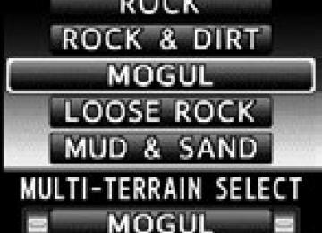
■ Selectable modes A mode which matches the road conditions can be selected from among the following 5 modes.
MUD & SAND LOOSE ROCK MOGUL ROCK & DIRT ROCK
Mode
Road Conditions
MUD & SAND
LOOSE ROCK
MOGUL
ROCK & DIRT
ROCK
Suitable for muddy roads, sandy roads, snow-covered roads, dirt trails and other slippery or dirty con- ditions Suitable for slippery conditions con- sisting of mixtures of earth and loose rock Suitable for very bumpy road condi- tions, such as mogul roads Suitable for very bumpy road condi- tions, such as mogul or rocky roads Suitable for rocky terrain
252
LC200_OM_OM60L09U_(U)
2-4. Using other driving systems
■ Multi-terrain Select control starting conditions
When all of the following conditions are satisfied, the Multi-ter- rain Select indicator will come on, the mode select screen will be displayed on the multi-information display, and Multi-terrain Select control will begin. ● The four-wheel drive control switch is in “L4”. ● Both Active TRAC and VSC are not off. ● Crawl Control is off.
■ Switching modes
Operate the Multi-terrain Select mode select switch dur- ing Multi-terrain Select control to select a mode.
Once the mode is confirmed, the mode name will be dis- played and the control will switch.
253
LC200_OM_OM60L09U_(U)
2-4. Using other driving systems
Statement on the multi-information display
Mode selection Display the Multi-terrain Select mode. The display switches in accor- dance with the pressing of the DISP switch (P. 190) or the conditions of each system. Mode status Display selected mode.
the name of
the
254
LC200_OM_OM60L09U_(U)
2
2-4. Using other driving systems
■Automatic system cancelation
In the following situations, the Multi-terrain Select indicator will go off, and Multi-terrain Select will be canceled automatically. ●When the four-wheel drive control switch is in “H4”. ●When Active TRAC and VSC are off. ●When Crawl Control is on.
■When it is difficult to generate traction
MUD & SAND mode provides the largest amount of tire slippage, followed by LOOSE ROCK, MOGUL, ROCK & DIRT and ROCK mode. Drivability can be improved by selecting a mode which provides a smaller amount of tire slippage than the current mode when the amount of tire slip- page is large, or conversely selecting a mode which provides a larger amount of tire slippage than the current mode when the amount of tire slip- page is small.
■When the vehicle is stuck
Switching the transfer and differential For the operation of the following functions, refer to the following pages. ●Four-wheel drive system (P. 240) ●Center differential lock (P. 240)
■When the brake system operates continuously
The brake system may overheat. In this case, a buzzer will sound, either the “TRAC OFF” will be displayed on the multi-information display, and Multi-ter- rain Select will be temporarily inoperable. In this event, stop the vehicle immediately in a safe place, and allow the brake system to cool down suffi- ciently. (There is no problem with continuing normal driving.) After a short time, the message on the multi-information display will go off, and you will be able to use Multi-terrain Select. ■When there is a malfunction in the system
The slip indicator light will come on. Have the vehicle inspected by your Toyota dealer immediately.
255
LC200_OM_OM60L09U_(U)
2-4. Using other driving systems
CAUTION
■When using the Multi-terrain Select
Observe the following precautions to avoid an accident that could result in death or serious injuries: ●There is a chance that the selected mode may not be the most appropriate in terms of road conditions such as pitch, slipperiness, undulation, etc. (P. 252)
●Multi-terrain Select is not intended to expand the limits of the vehicle. Check the road conditions thoroughly beforehand, and drive safely and carefully.
NOTICE
■Precaution for use
The Multi-terrain Select is intended for use during off-road driving. Do not use the system at any other time.
256
LC200_OM_OM60L09U_(U)
2
2-4. Using other driving systems Multi-terrain Monitor
The Multi-terrain Monitor displays the vehicle surroundings when driving at low speeds, thus assisting off-road driving and helping the driver to check the vehicle surroundings. ● By pressing the VIEW switch, the display can be shown, or the display image can be changed between the front screen, wide view front & side monitor screen, side-front simultaneous display monitor screen, side-rear simultaneous display monitor screen or rear screen. (The screens that can be selected differ depend- ing on the shift position and the transfer mode.)
● By referring to the guidelines shown on the front monitor screen, you can decide a driving line while assessing the distance to obstacles ahead of the vehicle and confirm the projected path, and by using the wide view front & side monitors, the side-front simultaneous display monitor and the side-rear simultaneous display monitor to identify objects in the vicinity or course of the tires, you can drive while preventing the vehicle from becoming stuck unexpectedly.
VIEW switch Touch screen
: If equipped 257
LC200_OM_OM60L09U_(U)
2-4. Using other driving systems
■ Switching the image
● When the shift lever is in “D”, “S” or “N”
Normal display mode: Press the VIEW switch to display the screen. Automatic display mode: The screen is displayed automatically. The screen will switch each time the VIEW switch is pressed. (The switching screen differs in accordance with the transfer range.)
Four-wheel drive
control switch position
Display
H4
L4
Wide view front & side monitor display
Side-front simultaneous display monitor
Side-rear simultaneous display monitor
Front monitor
Side-front simultaneous display monitor
Side-rear simultaneous display monitor
● When the shift lever is in “R” If the shift lever is shifted to “R”, the rear monitor (Toyota park- ing assist monitor) will be displayed, and the screen will switch every time the VIEW switch is pressed.
Rear monitor (Toyota parking assist monitor)
Side-front simultaneous display monitor
Side-rear simultaneous display monitor
258
LC200_OM_OM60L09U_(U)
2
2-4. Using other driving systems
■ Automatic display mode
In this mode, the screen is switched automatically in response to vehicle speed and shift lever operation, in addition to screen switching by operating the VIEW switch.
Touch “AUTO” on the front or wide view front & side monitor screen. The come on. Touch “AUTO” again to return to normal display mode.
indicator will
“AUTO”
259
LC200_OM_OM60L09U_(U)
2-4. Using other driving systems
Range covered by each camera
Front monitor* Side-front simultaneous dis- play monitor* Side-rear simultaneous dis- play monitor* Rear monitor
*:Range of wide view front & side monitor display (The monitor for side displays right side only.)
The illustration shown here is an example. As such, the actual visible area may be different. See P. 272 for information about the visual range of each camera.
260
LC200_OM_OM60L09U_(U)
Display
■ Front monitor
2-4. Using other driving systems
The image from the front camera is displayed. Use this monitor to help check the area in front of the vehicle for safety. Guidelines are shown to help determine the course.
■ Wide view front & side monitor display
Images from the front and the sides of the vehicle are dis- played.
This display is used to verify the situation at crossings with poor visibility, and to assist with safety confirmation when turning right. Guidelines can also be displayed as a steering guide when turning right.
■ Side-front simultaneous display monitor
The image from both side cam- eras is displayed. Use this moni- tor to help check the area on both sides of the vehicle at the same time, and to check for objects near the tires or the sides of the vehicle. Guidelines show- ing an image of the vehicle width and the position of the front tires are displayed.
261
LC200_OM_OM60L09U_(U)
2-4. Using other driving systems
■ Side-rear simultaneous display monitor
The image from both side cam- eras is displayed. Use this moni- tor to help check the area on both sides of the vehicle at the same time, and to check for objects near the tires or the sides of the vehicle. Guidelines show- ing an image of the vehicle width and the position of the rear tires are displayed. ■ Rear monitor (Toyota parking assist monitor)
The image from the rear camera is displayed. For information regarding the Toyota parking assist monitor, refer to “Naviga- tion System Owner’s Manual”.
262
LC200_OM_OM60L09U_(U)
2
2-4. Using other driving systems
Vehicle icon Displays the image being shown by the front monitor. Trajectory line (outside)* Indicates the outer path of the tire. Trajectory line (inside)* Indicates the inner path of the tire. Distance guideline (yellow) Shows the position about 3.3 ft. (1 m) away from the front edge of the vehicle. Distance guideline (red) Shows the position about 1.6 ft. (0.5 m) away from the front edge of the vehicle. Automatic display mode Switches the projected course mode
trajectory
The lines move according to the steering wheel position. *:While the Turn Assist function of Crawl Control is operating, the tra- jectory lines will be displayed as dotted lines. At this time, there may be a difference between the trajectory lines and the actual course of progression.
263
Using the monitor
■ Front monitor
LC200_OM_OM60L09U_(U)
2-4. Using other driving systems
Wide view front & side monitor display
Projected course line switch- ing button The course line display mode will change as follows each time the switch is touched. When the shift lever is in “R”, dis- play mode can not be changed. Vehicle icon Displays the image being shown by the front monitor. Front wheel contact point Shows the position of the vehi- cle’s front tire. Vehicle front edge line Shows the position of the vehi- cle’s leading edge. Projected course line (yellow) Displays a rough guide of the vehicle path that moves accord- ing to the steering wheel position. Displayed along with the mini- mum projected turning circle.
264
LC200_OM_OM60L09U_(U)
2
2-4. Using other driving systems
than 90
Minimum projected turning cir- cle (blue) Displays the smallest turning cir- cle projected by the system if the steering wheel is turned to full lock. Displayed when the steering wheel is turned to the right (fur- ther from straight ahead). Vehicle width line (blue) Indicates the width of the vehicle including the outside rear view mirror. Rear wheel contact point Shows the position of the vehi- cle’s rear tire. Automatic display mode Switches the projected course mode
265
LC200_OM_OM60L09U_(U)
2-4. Using other driving systems
■ Side-front simultaneous display monitor
Vehicle icon Displays the image being shown by the side-front simultaneous display monitor. Vehicle front edge line Shows the position of the vehi- cle’s front edge. Vehicle width line Indicates the width of the vehicle including the outside rear view mirror. Front wheel contact point Shows the position of the vehi- cle’s front tire.
266
LC200_OM_OM60L09U_(U)
2
2-4. Using other driving systems
■ Side-rear simultaneous display monitor
Vehicle icon Displays the image being shown by the side-rear simultaneous dis- play monitor. Vehicle width line Indicates the width of the vehicle including the outside rear view mirror. Rear wheel contact point Shows the position of the vehi- cle’s rear tire. Vehicle rear edge line Shows the position of the vehi- cle’s rear edge.
■ Rear monitor (Toyota park assist monitor)
Refer to “Navigation System Owner’s Manual”.
267
LC200_OM_OM60L09U_(U)
2-4. Using other driving systems
Projected course line display mode (Wide view front & side mon- itor display)
No course lines mode
Vehicle width line displayed.
Minimum projected turning circle display mode
The minimum projected turning circle line is added to the no course lines mode.
Turning course line display mode
is The projected course added to the minimum projected turning circle mode.
line
268
LC200_OM_OM60L09U_(U)
2-4. Using other driving systems
■ Switching projected course line display mode
Touch
Turning course line display mode
Minimum projected turning circle display mode
No course lines mode
■ Using the vehicle width line & course line
Vehicle width line
Use the vehicle width line to check the vehicle’s distance from objects such as curbstones etc. As shown in the illustration, be sure that the vehicle width line does not overlap the object. If you also move the vehicle so that the vehicle width line and the object are parallel, you can park parallel to the object.
269
LC200_OM_OM60L09U_(U)
2-4. Using other driving systems
Minimum projected turning circle & projected course line
Use the minimum projected turn- ing circle & projected course line (when displayed) to check the vehicle’s path with relation to obstacles. If the minimum projected turning circle line (blue) is over the obstacle as shown in the illustra- tion, or the obstacle falls within the minimum projected turning circle, if you turn with the mini- mum possible turning circle, the vehicle may collide with the object. When the projected course line (yellow) is displayed, be sure to operate the steering wheel so that the obstacle stays outside the projected course line until the vehicle has passed the object.
270
LC200_OM_OM60L09U_(U)
2-4. Using other driving systems
■The Multi-terrain Monitor can be operated when
Normal display mode The vehicle speed is less than approximately 7 mph (12 km/h). Automatic display mode ●When automatic display mode is selected ●When the shift lever is shifted to “D”, “S” or “N” ●When the shift lever is in “D”, “S” or “N” and the vehicle speed is below
approximately 6 mph (10 km/h)
■Automatic system cancellation
In the following situations, the image is canceled automatically. ●When the vehicle speed exceeds approximately 7 mph (12 km/h).
After the vehicle speed exceeds approximately 7 mph (12 km/h), the image will continue to be displayed for a short time. If the vehicle speed returns to below 7 mph (12 km/h) before the image extinguishes, the image will continue to be displayed.
●When “MAP” or another switch outside the screen has been pressed
■Interruption screens
An interruption screen is displayed when an obstacle is within the detection range of the intuitive parking assist. (P. 229)
■When the door mirrors are folded.
The screen will be turned off temporarily while the door mirrors are folding, and the screen will return to normal once folding has been completed.
271
LC200_OM_OM60L09U_(U)
2-4. Using other driving systems
■Displayed area
The area covered by the camera is limited. Objects which are close to either corner of the bumper or under the bumper cannot be seen on the screen. The area displayed on the screen may vary depending on vehicle orientation or road conditions.
Front camera
Camera’s field of view Objects visible to the camera Objects not visible to the camera Parts of the vehicle (bumper, grille, etc.)
272
LC200_OM_OM60L09U_(U)
2-4. Using other driving systems
Side camera (Wide view front & side monitor display)
Camera’s field of view Objects visible to the camera Right side of vehicle
273
LC200_OM_OM60L09U_(U)
2-4. Using other driving systems
Side camera (side-front simultaneous display monitor)
Camera’s field of view Objects visible to the camera Right side of vehicle Left side of vehicle
274
LC200_OM_OM60L09U_(U)
2-4. Using other driving systems