- 2009 Toyota Corolla Owners Manuals
- Toyota Corolla Owners Manuals
- 2010 Toyota Corolla Owners Manuals
- Toyota Corolla Owners Manuals
- 2004 Toyota Corolla Owners Manuals
- Toyota Corolla Owners Manuals
- 1999 Toyota Corolla Owners Manuals
- Toyota Corolla Owners Manuals
- 2001 Toyota Corolla Owners Manuals
- Toyota Corolla Owners Manuals
- 1996 Toyota Corolla Owners Manuals
- Toyota Corolla Owners Manuals
- 2015 Toyota Corolla Owners Manuals
- Toyota Corolla Owners Manuals
- 2013 Toyota Corolla Owners Manuals
- Toyota Corolla Owners Manuals
- 2007 Toyota Corolla Owners Manuals
- Toyota Corolla Owners Manuals
- 2000 Toyota Corolla Owners Manuals
- Toyota Corolla Owners Manuals
- 2012 Toyota Corolla Owners Manuals
- Toyota Corolla Owners Manuals
- 1998 Toyota Corolla Owners Manuals
- Toyota Corolla Owners Manuals
- 1997 Toyota Corolla Owners Manuals
- Toyota Corolla Owners Manuals
- 2003 Toyota Corolla Owners Manuals
- Toyota Corolla Owners Manuals
- 2019 Toyota Corolla Owners Manuals
- Toyota Corolla Owners Manuals
- Download PDF Manual
-
S Keep the belts clean and dry. If they need cleaning, use a mild soap solution or lukewarm water. Never use bleach, dye, or abrasive cleaners−they may severely weak- en the belts.
S Replace the built−in child re- straint assembly if it has been used in a severe impact. The en- tire assembly should be replaced even if damage is not obvious.
S Do not use a separate child re- straint system over the opened built−in child restraint.
S When the built−in child restraint is in use, do not use the adult lap and shoulder belt instead of the built− in child restraint seat belt as it can cause severe injury to the child in a sudden stop or crash.
1. Separate the fastener tapes behind the head restraint to separate the head pad from the seatback. Lower the child restraint cushion and fold back the head pad under the child restraint cushion.
CAUTION
Do not use the built−in child re- straint with the head pad unfolded.
2. While pulling the seat belt release strap (black), pull both shoulder belts together.
Pull the seat belt release strap from above at about 45_ angle to the child seat cush- ion. If the shoulder belts cannot be pulled out, return the child seat cushion to an almost closed position, firmly pull the seat belt re- lease strap and at the same time pull both shoulder belts, then lower the child seat cushion again.
3. Compress the shoulder belt clip to separate the right and left shoulder belts.
43
CAUTION
If you have removed the child seat pad for cleaning etc., do not use the built−in child restraint without the pad.
1. Add slack to the shoulder belts by pulling both of them together while pulling the black seat belt release strap (see step 4 for illustrated instruction). Then pull down the seatback part of the removable pad. Determine the proper shoulder belt slot height for your child. Select the slots at or just above the top of the child’s shoulders.
The removable pad is attached by fasten- er tapes.
44
To move the shoulder belts from the lower slot to the upper slot: 1. Slide the belt up tp the top of the seat-
back.
2. Slide the belt down to the outer side of
the upper slot.
3. Squeeze the remaining edge of the seat belt down into the inner side of the upper slot.
You may have to push some belt material through the slot in order to move the belt. To move the belt to the lower position, re- verse this procedure.
S When the built−in child restraint is in use, do not use the adult lap and shoulder belt instead of the built− in child restraint seat belt as it can cause severe injury to the child in a sudden stop or crash.
S After moving the shoulder belts, make sure the belts are properly routed and that they are not twisted or flipped over.
Make sure both belts are adjusted to the same height. After moving the shoulder belts, press the removable pad against the fastener tapes and install the pad to the seatback. Make sure the belts go through the slots in the pad that match the shoulder belt slots be- ing used.
CAUTION
S If your child’s shoulders are above the upper shoulder belt position, do not use the built−in child re- straint. Your child should use the adult lap and shoulder belt.
5. Sit the child on the child seat. Place a shoulder belt over each shoulder. Insert the tabs into the buckle.
CAUTION
S After inserting the tabs, make sure the tabs and buckle are locked and that the shoulder belts and buckle strap are not twisted. S Do not insert coins, clips, etc. in the buckle as this may prevent you from properly latching the tabs and buckle.
45
S If the seat belt does not function normally, it cannot protect your child from injury. Contact your Toy- ota dealer immediately. Do not use the built−in child restraint until the seat belt is fixed.
46
6. Fasten the shoulder belt clip. The purpose of the clip is to keep the shoulder belts positioned correctly on the shoulders.
CAUTION
An unfastened shoulder belt clip will not keep the belts on the child’s shoulders. In a sudden stop or crash, the child may go too far for- ward and be seriously injured. Make sure the belt clip is fastened at all ti
7. Pull the seat belt adjustment strap (gray tab) firmly until the shoulder belts are snugly adjusted around the child’s shoulders.
You should not be able to put more than two fingers between a shoulder belt and the child’s chest. After adjusting the shoulder belt tight- ness, move the shoulder belt clip 5 to 8 cm (2 to 3 in.) below the child’s chin. On each belt, the shoulder part should be centered on the child’s shoulder. The belts should be away from the child’s face and neck, but not falling off the child’s shoulders.
8. To release the child from the seat belts, separate the shoulder belt then press the buckle release but- ton.
Move both belts off the child’s shoulder’s.
9. To store the built−in child restraint, fasten the shoulder belt clip and re- turn the seat belt buckle using the fastener tapes. Fold up the seat belt adjustment strap (gray tab) in the seat so that the edge of the strap does not come out of the raised seat cushion. Raise the seat cush- ion and return the head pad by en- gaging the fastener tapes while pressing the child restraint cush- ion and head pad firmly.
—Types of child restraint system Child restraint systems are classified into the following 3 types depending on the child’s age and size. (A)Infant seat (B)Convertible seat (C)Booster seat Install the child restraint system following the instructions provided by its manufac- turer.
47
—Installation with 2−point type seat belt
(A)INFANT SEAT INSTALLATION An infant seat is used in rear−facing position only.
48
1. Run the center lap belt through or around the infant seat following the in- structions provided by its manufactur- er and insert the tab into the buckle taking care not to twist the lap belt.
CAUTION
Do not put a rear−facing child re- straint system in the rear seat if it interferes with the lock mechanism of the front seats. This can cause severe injury to the child and front passenger in case of sudden brak- ing or a collision.
CAUTION
S After inserting the tab, make sure the tab and buckle are locked and that the lap belt is not twisted.
S Do not insert coins, clips, etc. in the buckle as this may prevent you from properly latching the tab and buckle.
S If the seat belt does not function normally, it cannot protect your child from injury. Contact your To- yota dealer immediately. Do not use the seat until the seat belt is fixed.
49
2. While pressing the infant seat firmly against the seat cushion and seat- back, tighten the lap belt by pulling its free end to hold the infant seat secure- ly.
CAUTION
Push and pull the child restraint system in different directions to be sure it is secure. Follow all the installation instructions provided by its manufacturer.
3. To remove the infant seat, press the
buckle−release button.
50
(B)CONVERTIBLE SEAT INSTALLA-
TION
CAUTION
A convertible seat is used in forward facing and rear−facing position de- pending on the child’s age and size. When the manufacturer’s instructions about the applicable child’s age and size as well as direction for installing of a child re- straint system.
installing,
following
Do not put a rear−facing child re- straint system in the rear seat if it in- terferes with the lock mechanism of the front seats. This can cause se- vere injury to the child and front passenger in case of sudden brak- ing or a collision.
1. Run the center lap belt through or around the convertible seat following the instructions provided by its manufacturer and insert the tab into the buckle taking care not to twist the lap belt.
51
CAUTION
S After inserting the tab, make sure the tab and buckle are locked and that the lap belt is not twisted.
S Do not insert coins, clips, etc. in the buckle as this may prevent you from properly latching the tab and buckle.
S If the seat belt does not function normally, it cannot protect your child from injury. Contact your To- yota dealer immediately. Do not use the seat until the seat belt is fixed.
52
2. While pressing the convertible seat firmly against the seat cushion and seatback, tighten the lap belt by pulling its free end to hold the convertible seat securely.
CAUTION
Push and pull the child restraint system in different directions to be sure it is secure. Follow all the installation instructions provided by its manufacturer.
—Installation with 3−point type seat belt
3. To remove the convertible seat, press
the buckle−release button.
(A) INFANT SEAT INSTALLATION An infant seat is used in rear−facing position only.
CAUTION
S Vehicles with a passenger airbag: Never put a rear−facing child re- straint system in the front seat be- cause the force of the rapid infla- tion of the passenger airbag can cause death or serious injury to the child.
53
CAUTION
S After inserting the tab, make sure the tab and buckle are locked and that the lap belt is not twisted.
S Do not insert coins, clips, etc. in the buckle as this may prevent you from properly latching the tab and buckle.
S If the seat belt does not function normally, it cannot protect your child from injury. Contact your To- yota dealer immediately. Do not use the seat until the seat belt is fixed.
S Do not put a rear−facing child re- straint system in the rear seat if it interferes with the lock mecha- nism of the front seats. This can cause severe injury to the child and front passenger in case of sudden braking or a collision.
1. Run the lap and shoulder belt through or around the infant seat following the instructions provided by its manufac- turer and insert the tab into the buckle taking care not to twist the belt. Keep the lap portion of the belt tight.
54
2. Fully extend the shoulder belt to put it in the lock mode. When the belt is then retracted even slightly, it cannot be ex- tended.
To hold the infant seat securely, make sure the belt is in the lock mode before let- ting the belt to retract.
3. While pressing the infant seat firmly against the seat cushion and seat- back, let the shoulder belt retract as far as it will go to hold the infant seat se- curely.
CAUTION
Make sure the seat belt is securely locked. Also make sure the child re- straint system is secure by pushing and pulling it in different directions. Follow all the installation instruc- tions provided by its manufacturer.
55
4. To remove the infant seat, press the buckle−release button and allow the belt to retract completely. The belt will move freely again and be ready to work for an adult or older child passen- ger.
(B)CONVERTIBLE SEAT INSTALLA-
TION
A convertible seat is used in forward- facing and rear−facing position de- pending on the child’s age and size. When installing, follow the manufac- turer’s instruction about the applica- ble child’s age and size as well as di- rection installing of a child restraint system.
for
CAUTION
S Vehicles with a passenger airbag:
Never put a rear−facing child re- straint system in the front seat be- cause the force of the rapid infla- tion of the passenger airbag can cause death or serious injury to the child.
56
S A forward−facing child restraining system should be put on the front seat only when it is unavoidable. Always move the seat as far back as possible, because the force of a deploying airbag could cause death or serious injury to the child.
S Do not put a rear−facing child re- straint system in the rear seat if it interferes with the lock mecha- nism of the front seats. This can cause severe injury to the child and front passenger in case of sudden braking or a collision.
1. Run the lap and shoulder belt through or around the convertible seat follow- ing the instructions provided by its manufacturer and insert the tab into the buckle taking care not to twist the belt. Keep the lap portion of the belt tight.
57
CAUTION
S After inserting the tab, make sure the tab and buckle are locked and that the lap and shoulder portions of the belt are not twisted.
S Do not insert coins, clips, etc. in the buckle as this may prevent you from properly latching the tab and buckle.
S If the seat belt does not function normally, it cannot protect your child from injury. Contact your To- yota dealer immediately. Do not use the seat until the seat belt is fixed.
58
2. Fully extend the shoulder belt to put it in the lock mode. When the belt is then retracted slightly, it cannot be ex- tended.
To hold the convertible seat securely, make sure the belt is in the lock mode be- fore letting the belt to retract.
3. While pressing the convertible seat firmly against the seat cushion and seatback, let the shoulder belt retract as far as it will go to hold the convert- ible seat securely.
CAUTION
S Make sure the seat belt is securely locked. Also make sure the child restraint system is secure by pushing and pulling it in different directions. Follow all the installa- tion instructions provided by its manufacturer.
4. To remove the convertible seat, press the buckle−release button and allow the belt to retract completely. The belt will move freely again and be ready to work for an adult or older child passen- ger.
(C)BOOSTER SEAT INSTALLATION A booster seat is used in forward−fac- ing position only.
59
CAUTION
S Always make sure the shoulder belt is positioned across the cen- ter of child’s shoulder. The belt should be kept away from child’s neck, but not falling off child’s shoulder. Failure to do so could re- duce the amount of protection in an accident and cause serious in- juries in a collision.
S High−positioned
lap belts and loose−fitting belts both could cause serious injuries due to slid- ing under the lap belt during a col- lision. Keep the lap belt positioned as low on hips as possible.
S For child’s safety, do not place the
shoulder belt under child’s arm.
S After inserting the tab, make sure the tab and buckle are locked and that the lap and shoulder portions of the belt are not twisted.
S Do not insert coins, clips, etc. in the buckle as this may prevent you from properly latching the tab and buckle.
CAUTION
A forward−facing child restraint system should be put on the front seat only when it is unavoidable. Al- ways move the seat as far back as possible because the force of a de- ploying airbag could cause death or serious injury to the child.
1. Sit the child on a booster seat. Run the lap and shoulder belt through or around the booster seat and child fol- lowing the instructions provided by its manufacturer and insert the tab into the buckle taking care not to twist the belt.
Make sure the shoulder belt is correctly across the child’s shoulder and that the lap belt is positioned as low as possible on child’s hips. See “Seat belts” for details.
60
S If the seat belt does not function normally, it cannot protect your child from injury. Contact your To- yota dealer immediately. Do not use the seat until the seat belt is fixed.
—Top strap anchors and locations
2. To remove the child restraint system, press the buckle−release button and allow the belt to retract.
If your child restraint system requires the use of a top strap, latch the hook onto the anchor bracket and tighten the top strap. See the following instructions to install the anchor brackets.
61
Without filler panel trim— a. Remove the cap on the filler panel you wish to use. b. Insert a 10 mm (0.4 in.) spacer and tighten down the anchor bracket for your child restraint system with a bolt. Torque the bolt to 16.5—24.7 N⋅m (1.68—2.52
kgf⋅m, 12.2—18.2 ft⋅lbf). To comply with Canada Motor Vehicle Safety Standards, vehicles sold in Cana- da are provided with a bracket set in the glovebox, designed for use with any of the 3 anchor locations shown in the illustra- tion. If your child restraint system does not pro- vide any of the necessary parts, ask your Toyota dealer. (See “—Child restraint sys- tem”.)Tilt steering wheel
To change the steering wheel angle, pull up the lock release lever, tilt the steering wheel to the desired angle and release the lever.
CAUTION
S Do not adjust the steering wheel
while the vehicle is moving.
S After adjusting the steering wheel, try moving it up and down to make sure it is locked in position.
On the filler panel behind the rear seat With filler panel trim— a. Using the illustration as a guide, run your fingers across trim of the filler pan- elitself to locate the position of the holes underneath. b. Make a hole in the covering directly above the hole in the filler panel. c. Insert a 10 mm (0.4 in.) spacer and tighten down the anchor bracket for your child restraint system with a bolt. Torque the bolt to 16.5−24.7 N⋅m (1.68−2.52 kgr- ⋅m, 12.2−18.2 ft⋅lf).
62
Outside rear view mirrors—
—Rear view mirror remote control
CAUTION
Do not adjust the mirror while the vehicle is moving. It may cause the driver to mishandle the vehicle and an accident may occur resulting in personal injuries.
Adjust the mirror so you can just see the side of your vehicle in the mirror. Be careful when judging the size or dis- tance of any object seen in the outside rear view mirror on the passenger’s side. It is a convex mirror with a curved surface. Any object seen in a convex mirror will look smaller and farther away than when seen in a flat mirror.
To adjust the rear view mirror, simply operate the control lever.
NOTICE
If ice should jam the mirror, do not operate the control or scrape the mirror face. Use a spray de−icer to free the mirror.
63
—Power rear view mirror control
—Folding rear view mirrors
Anti−glare inside rear view mirror
To adjust a power rear view mirror, first push the master switch in “L’ (left) or “R” (right) depending on which mirror needs adjusting, then push the con- trol switch in desired direction. If the engine is not running, the key must be in the “ACC” position.
NOTICE
If ice should jam the mirror, do not operate the control or scrape the mirror face. Use a spray de−icer to free the mirror.
64
To fold the rear view mirror, push back- ward. The rear view mirrors can be folded back- ward for parking in restricted areas.
CAUTION
Do not drive with the mirrors folded down, or it may cause an accident due to a poor or inaccurate view of objects to the rear.
Pull the lever toward you to reduce glare from the headlights of the ve- hicle behind you during night driving. Before adjusting the mirror to the position with most clarity, push the day−night chang lever away from you (daylight driv- ing position). Remember that by reducing glare you also lose some rear view clarity.
Part 1
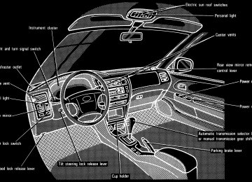
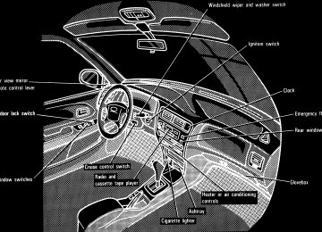
OPERATION OF INSTRUMENTS AND CONTROLS—Chapter 1−4
Lights, Wipers and Defogger S Headlights and turn signals S Emergency flashers S Instrument panel light control S Interior light S Personal lights S Windshield wipers and washer S Rear window defoggerHeadlights and turn signals
To turn the lights on, twist the knob on the end of the lever. Daytime running light system (Canada only)—The headlights turn on when the parking brake is released with the engine started, even with the light switch in the “OFF” position. They will not go off until the ignition switch is turned off. The turn on the other exterior lights and in- strument panel lights, twist the knob to the first clickstop. Under the daytime running light system, the headlights turn on at reduced intensi- ty. Twist the knob to the position 2 to turn to full intensity for driving at night.
FIRST CLICKSTOP: Only the parking, tail, license plate, side marker and instru- ment panel lights turn on. SECOND CLICKSTOP: The headlights also turn on. If you remove the key with the headlights left on, a buzzer reminds you to turn the lights off when you open the driver’s door.
NOTICE
To prevent the battery from being discharged, do not leave the lights on for a long period when the engine is not running.
65
Emergency flashers
For high beam, push the lever away from you. Pull it toward you for low beam. For the headlight flasher, pull it further back. A blue light in the instrument panel indi- cates high beam is on. The headlight flasher works even when the headlight switch is off.
For signaling turns, move the lever up or down in the conventional manner. The key must be in the ”ON” position. The turn signal is self−cancelling after a turn, but after a lane change, you may have to cancel it by hand. You can also signal a lane change by moving the turn signal lever partway and holding it there. If the green light in the instrument panel flashes faster than normal, it indicates that the front or rear turn signal bulb has burned out.
To turn on the emergency flashers, push the switch. All the turn signal lights will flash. To turn them off, push the switch once again. Turn on the emergency flashers to warn other drivers if your vehicle must be stopped where it might be a traffic hazard. Always pull as far off the road as possible. The turn signal light switch will not work when the emergency flashers are operat- ing.
66
Instrument panel light control
Interior light
NOTICE
To prevent the battery from being discharged, do not leave the lights on for a long period when the engine is not running.
To adjust the brightness of the instru- ment panel lights, turn the dial.
To turn on the interior light, slide the switch. With the switch in the “DOOR” position, the light comes on when any of the side doors and back door are opened.
67
Personal light
Windshield wipers and washer (intermittent type without interval adjuster)
NOTICE
Do not operate the wipers if the windshield is dry. It may scratch the glass.
To turn on the personal light, push the switch. To turn it off, push the switch once again.
To turn the wipers on, move the lever. To make the washer squirt, push the button on the end of the lever. The key must be in the ”ON” position. The wipers will operate at intervals when the lever is in the ”INT” position. If the washer does not work, check to see whether the washer tank is empty. For in- formation on adding washer fluid, see ’Ad- ding washer fluid” in Chapter 7−3. In cold weather, warm the windshield with the defroster before using the washer. This will help prevent icing, which could block your vision.
68
Windshield wipers and washer (intermittent type with interval adjuster)
Windshield wipers and washer (mist type)
If the washer does not work, check to see whether the washer tank is empty. For in- formation on adding washer fluid, see “Adding washer fluid” in Chapter 7−3. In cold weather, warm the windshield with the defroster before using the washer. This will help prevent icing, which could block your vision.
NOTICE
Do not operate the wipers if the windshield is dry. It may scratch the glass.
To turn the wipers on, move the lever. To make the washer squirt, push the button on the end of the lever. The key must be in the “ON” position. The wipers will operate at intervals when the lever is in the “INT” position. With the lever in this position, the wipers can be ad- justed to operate at intervals of 3 to 10 se- conds depending on the interval adjuster setting between “S” and “F”. Also, the wipers will automatically operate a couple of times after the washer squirts even with the lever in the “OFF” position.
To turn the wipers on, move the lever. To make the washer squirt, push the button on the end of the lever. The key must be in the “ON” position. If a single wipe is desired in mist push the lever to the “MIST” position and release it. If the washer does not work, check to see whether the washer tank is empty. For in- formation on adding washer fluid, see “Adding washer fluid” in Chapter 7−3. In cold weather, warm the windshield with the defroster before using the washer. This will help prevent icing, which could block your vision.
69
Rear window defogger
NOTICE
Do not operate the wipers if the windshield is dry. It may scratch the glass.
To defog or defrost the rear window, push the switch. The key must be in the “ON” position. The thin heater wires on the inside of the rear window will quickly clear the surface. An indicator light will illuminate to indicate the defogger is operating. Push the switch once again to turn the de- fogger off. With timer: The system will automatically shut off after the defogger has operated about 15 minutes.
Make sure you turn the defogger off when the window is clear. Leaving the defogger on for a long time could cause the battery to discharge, especially during stop−and− go driving. The defogger is not designed for drying rain water or for melting snow.
NOTICE
zWithout timer: To prevent the bat- tery from being discharged, turn the switch on when the engine is running.
zWhen cleaning the inside of the rear window, be careful not to scratch or damage the heater wires.
70
Part 1
OPERATION OF INSTRUMENTS AND CONTROLS—Chapter 1−5
Gauges, Meters and Service reminder indicators S Fuel gauge S Engine coolanttemperature
gauge
S Tachometer S Odometer and trip meter S Service reminder indicators and
warning buzzers
Fuel gauge
If the fuel tank is completely empty, the malfunction indicator lamp comes on. Fill the fuel tank immediately.
The gauge works when the ignition switch is on and indicates the approxi- mate quantity of fuel remaining in the tank. It is a good idea to keep the tank over 1/4
full. This fuel gauge has a non−return type needle which remains at the last indicated position when the ignition switch is turned off. If the level approaches “E” or the low fuel level warning light comes on, fill the fuel tank as soon as possible.The indicator lamp goes off after driving several times. If the indicator lamp does not go off, contact your Toyota dealer as soon as possible.
71
Engine coolant temperature gauge
Tachometer
The gauge indicates the engine cool- ant temperature when the ignition switch is on. The engine operating temperature will vary with changes in weather and engine load. If the needle moves into the red zone, your engine is too hot. If your vehicle overheats, stop your vehicle and allow the engine to cool. Your vehicle may overheat during severe operating conditions, such as: S Driving up a long hill on a hot day. S Reducing speed or stopping after high
speed driving.
Idling for a long period with the air con- ditioning on in stop−and−go traffic.
S Towing a trailer
NOTICE
zDo not remove the thermostat in the engine cooling system as this may cause the engine to overheat. The thermostat is designed to con- trol the flow of coolant to keep the temperature of the engine within the specified operating range.
zDo not continue driving with an overheated engine. See “If your ve- hicle overheats” in Part 4.
tachometer
The indicates engine speed in thousands of rpm (revolu- tions per minute). Use it while driving to select correct shift points and to prevent engine lugging and overrev- ving. Driving with the engine running too fast causes excessive engine wear and poor fuel economy. Remember, in most cases the slower the engine speed, the greater the fuel economy.
NOTICE
Do not let the indicator needle get into the red zone. This may cause severe engine damage.
72
Odometer and trip meter
Service reminder indicators and warning buzzers
The odometer records the total dis- tance the vehicle has been driven. The trip meter may be set to zero to record the distance on each trip. To reset the trip meter, press the trip meter reset knob. The black digits on white indicate tenths of kilometers or miles.
73
(a) Brake System Warning Light This light has the following functions: Parking brake reminder If this light is on, make sure the parking brake is fully released. The light should go off. Low brake fluid level warning If this light comes on and stays on while you are driving, slowdown and pull off the road. Then stop the vehicle carefully. There maybe a problem somewhere in the brake system. check the fluid level of the see−through reservoir. To make sure the parking brake has not caused the warning light to come on, check to see that the parking brake is fully released. If the brake fluid level is low... At a safe place, test your brakes by start- ing and stopping.
If you judge that the brakes still work adequately, drive cautiously to your nearest dealer or shop for repairs. If the brakes are not working, have the vehicle towed in for repairs. (For tow- ing information, see Part 4.)
74
CAUTION
It is dangerous to continue driving normally when the brake fluid level is low.
If the brake fluid level is correct... Have the warning system checked by your Toyota dealer. (b) Seat Belt Reminder Light and Buzz-
er
Once the ignition key is turned to “ON” or “START”, the reminder light and buzzer come on if the driver’s seat belt is not fas- tened. Unless the driver fastens the belt, the light stays on and the buzzer stops af- ter about 4 to 8 seconds. (c) Discharge Warning Light This light warns that the battery is being discharged. If it comes on while you are driving, there is a problem somewhere in the charging system. The engine ignition will continue to oper- ate, however, until the battery is dis- charged. Turn off the air conditioning, blower, radio, ect., and drive directly to the nearest Toyota dealer or repair shop.
NOTICE
if the Do not continue driving engine drive belt is broken or loose.
(d) Low Oil Pressure Warning Light This light warns that the engine oil pres- sure is too low. If it flickers or stays on while you are driv- ing, pull off the road to a safe place and stop the engine immediately. Call a Toyo- ta dealer or qualified repair shop for assis- tance. The light may occasionally flicker when the engine is idling or it may come on brief- ly after a hard stop. There is no cause for concern if it then goes out when the en- gine is accelerated slightly. The light may come on when the oil level is extremely low. It is not designed to indi- cate low oil level, and the oil level must be checked using the level dipstick.
NOTICE
Do not drive the vehicle with the warning light on—even for one block. It may ruin the engine.
(e) Low Fuel Level Warning Light This light comes on when the fuel level in the tank becomes nearly empty. Fill up the tank as soon as possible. (f) “ABS” Warning Light This light warns that there is a problem somewhere in your anti−lock brake sys- tem. If the light comes on while you are driving, have your vehicle checked by your Toyota dealer as soon as possible. The light will come on when the ignition key is turned to the “ON” position. After about 3 seconds, the light will go off. When the “ABS” warning light is on (and the brake system warning light is off), the brake system operates conventionally but anti−lock brake system is not assisting brake performance so that the wheels can lock−up during sudden braking or braking on slippery road surfaces. (g) Open Door Warning Light This light remains on until all the side doors and back door are completely closed.
(h) SRS Airbag Warning Light This light will come on when the igni- tion key is turned to the “ACC” or “ON” position. After about 6 seconds, the light will go off. This means the airbag system is operating properly. The warning light system monitors the front airbag sensors, center airbag sensor assembly, inflators, warning light, inter- connecting wiring and power sources. If either of the following conditions occurs, this indicates a malfunction somewhere in the parts monitored by the warning light system. Contact your Toyota dealer as soon as possible to service the vehicle. S The light does not come on when the ignition key is turned to the “ACC” or “ON” position or remains on.
S The light comes on while driving. (i) Malfunction Indicator Lamp This lamp comes on in the following cases. a. The fuel tank is completely empty. (See “Fuel gauge” in Chapter 1−5 for in- structions.) b. There is a problem somewhere in your engine or automatic transmission electri- cal system.
If it comes on while you are driving in case b, have your vehicle checked/repaired by your Toyota dealer as soon as possible. (j) Key Reminder Buzzer This buzzer reminds you to remove the key when you open the driver’s door with the ignition key in the “ACC” or “LOCK” position. (k) Light Reminder Buzzer This buzzer will sound if the driver’s door is opened with the key removed from the ignition switch and the headlight switch left on. CHECKING SERVICE REMINDER INDI- CATORS (except the low fuel level warning light) 1. Apply the parking brake. 2. Open one of the side doors or back
door. The open door warning light should come on.
3. Close the door.
The open door warning light should go off.
4. Turn the ignition key to “ACC”.
The SRS airbag warning light should come on. It goes off after about 6 sec- onds.
75
5. Turn the ignition key to “ON”, but do
not start the engine. All the service reminder indicators ex- cept the open door warning light and SRS airbag warning light should come on. The “ABS” warning light goes off after about 3 seconds.
If any service reminder indicator or warn- ing buzzer does not function as described above, either the bulb is burned out or the circuit is in need of repair. Have it checked by your Toyota dealer as soon as pos- sible.
76
Part 1
OPERATION OF INSTRUMENTS AND CONTROLS—Chapter 1−6
Ignition switch, Transmission and Parking brakeS Ignition switch with steering lock S Automatic transmission S Manual transmission S Parking brake S Cruise control
Ignition switch with steering lock
“Start” − Starter motor on. The key will return to the “ON” position when re- leased. For starting tips, see Part 3. “ON” − Engine on and all accessories on. This is the normal driving position. “ACC” − Accessories such as the ra- dio operate, but the engine is off. If you leave the key in the “ACC” or “LOCK” position and open the driver’s door, a buzzer will remind you to remove the key.
“LOCK” − Engine is off and the steer- ing wheel is locked. The key can be re- moved only at this position. You must push in the key to turn the key from “ACC” to the “LOCK” position. On vehicles with an automatic transmission, the selector lever must be in the “P” posi- tion before pushing the key. When starting the engine, the key may seem stuck at the “LOCK” position. To free it, first be sure the key is pushed all the way in, and then rock the steering wheel slightly while turning the key gently.
CAUTION
For manual transmission: Never remove the key when the ve- hicle is moving, as this will lock the steering wheel and result in loss of steering control.
NOTICE
Do not leave the key in the “ON” position if the engine is not running. The battery will discharge and the ignition could be damaged.
77
Automatic transmission (3−speed type)
Vehicles with cruise control − When the cruise control is being used, even if you downshift the transmission, engine braking will not be applied because the cruise control is not cancelled. For ways to decrease the vehicle speed, see “Cruise control” in this chapter.
78
Your automatic transmission has a shift lock system to minimize the possibility of incorrect operation. This means you can only shift out of “P” position when the brake pedal is depressed (with the ignition switch in “ON” position and the lock re- lease button depressed). (a) Normal Driving 1. Start the engine as instructed in “How to start the engine” in Part 3. The trans- mission must be in “P” or “N”.
2. With your foot holding down the brake
pedal, shift the selector lever to “D”.
In “D” position, the automatic transmis- sion system will select the most suitable gear for running conditions such as nor- mal cruising, hill climbing, hard towing, etc.
S Shift into the “2” position when the ve- hicle speed is lower than the 90 km/h (56 mph). The transmission will down- shift to the second gear and more en- gine braking will be obtained.
S Shift into the “L” position when the ve- hicle speed is lower than 36 km/h (22
mph). The transmission will downshift to the first gear and maximum engine braking will be applied.Vehicles with cruise control—When the cruise control is being used, even if you downshift the transmission, engine brak- ing will not be applied because the cruise control is not cancelled. For ways to de- crease the vehicle speed, see “Cruise control” in this chapter.
CAUTION
CAUTION
Never put your foot on the accelera- tor pedal while shifting. 3. Release the parking brake and brake pedal. Depress the accelerator pedal slowly for smooth starting.
(b) Using engine braking To use engine braking, you can downshift the transmission as follows:
Be careful when downshifting on a slippery surface. Abrupt shifting could cause the vehicle to spin or skid.
(c) Using the “2” and “L” positions The “2” and “L” positions are used for strong engine braking as described pre- viously.
With the selector lever in “2” or “L”, you can start the vehicle in motion as with the lever in “D”. With the selector lever in “2”, the vehicle will start in the first gear and automatically shift to the second gear. With the selector lever in “L”, the trans- mission is engaged in the first gear.
NOTICE
zBe careful not to overrev the en- gine. Watch the tachometer to keep engine rpm from going into the red zone. The approximate maximum allowable speed for each position is given below for your reference: . . . . . . . . . . .
112 km/h (70 mph) 62 km/h (38 mph)
“2” “L”
zDo not continue hill climbing or hard towing for a long time in the “2” or “L” position. This may cause severe automatic trasmis- sion damage from overheating. To prevent such damage, “D” posi- tion should be used in hill climb- ing or hard towing.
79
(d) Backing up 1. Bring the vehicle to a complete stop. 2. With the brake pedal held down with your foot, shift the selector lever to the “R” position.
NOTICE
Never shift into reverse while the vehicle is moving.
(e) Parking 1. Bring the vehicle to a complete stop. 2. Pull the parking brake lever up fully to
securely apply the parking brake.
3. With the brake pedal pressed down, shift the selector lever to the “P” posi- tion.
CAUTION
While the vehicle is moving, never attempt to move the selector lever into “P” position under any circum- stances. Serious mechanical dam- age and loss of vehicle control may result.
80
(f) Good driving practice
CAUTION
Always keep your foot on the brake pedal while stopped with the engine running. This prevents the vehicle from creeping.
NOTICE
Do not hold the vehicle on an upgrade with the accelerator pedal. It can cause the transmission to overheat. Always use the brake pedal or parking brake.
(g) Rocking your vehicle if stuck
CAUTION
If you rock your vehicle to make it out when it becomes stuck in snow, mud, sand, etc., first check that there is no physical object or peo− ple around the vehicle. During ope− ration, the vehicle may suddenly move forward or backward, causing injury or damage to nearby people or objects.
NOTICE
If you rock your vehicle, observe the following precautions to prevent damage to the transmission and other parts. zDo not depress the accelerator pedal while shifting the selector lever or before the transmission is completely shifted to forward or reverse gear.
zDo not race the engine and avoid
spinning the wheels.
zIf your vehicle remains stuck after rocking the vehicle several times, consider other ways such as tow- ing.
(h) If you cannot shift the selector lever
out of “P” position
If you cannot shift the selector lever from “P” position even though the brake pedal is depressed, use the shift lock override button. For instructions, see “If you can- not shift automatic transmission slelector lever” in Part 4.
Automatic transmission (4−speed type)
Vehicles with cruise control − When the cruise control is being used, even if you downshift the transmission, engine braking will not be applied because the cruise control is not cancelled. For ways to decrease the vehicle speed, see “Cruise control” in this chapter.
81
Your automatic transmission has a shift lock system to minimize the possibility of incorrect operation. This means you can only shift out of “P” position when the brake pedal is depressed (with the ignition switch in “ON” position and the lock re- lease button depressed). (a) Normal Driving 1. Start the engine as instructed in “How to start the engine” in Part 3. The trans- mission must be in “P” or “N”.
2. With your foot holding down the brake
pedal, shift the selector lever to “D”.
In “D” position, the automatic transmis- sion system will select the most suitable gear for running conditions such as nor- mal cruising, hill climbing, hard towing, etc. Always turn the overdrive switch on for better fuel economy and quieter driving. If the engine coolant temperature is low, the transmission will not shift into the over- drive gear even with the overdrive switch on.
CAUTION
Never put your foot on the accelera- tor pedal while shifting.
82
3. Release the parking brake and brake pedal. Depress the accelerator pedal slowly for smooth starting.
(b) Using engine braking To use engine braking, you can downshift the transmission as follows: S Turn off the overdrive switch. The “O/D OFF” indicator light will come on and the transmission will downshift to the third gear.
S Shift into the “2” position. The trans- mission will downshift to the second gear when the vehicle speed drops down to or lower than 90 km/h (56
mph), and more powerful engine brak- ing will be obtained.S Shift into the “L” position. The trans- mission will downshift to the first gear when the vehicle speed drops down to or lower than the 42 km/h (26 mph) and maximum engine braking will be ap- plied.
Vehicles with cruise control—When the cruise control is being used, even if you downshift the transmission, engine brak- ing will not be applied because the cruise control is not cancelled. For ways to de- crease the vehicle speed, see “Cruise control” in this chapter.
CAUTION
Be careful when downshifting on a slippery surface. Abrupt shifting could cause the vehicle to spin or skid.
(c) Using the “2” and “L” positions The “2” and “L” positions are used for strong engine braking as described pre- viously. With the selector lever in “2” or “L”, you can start the vehicle in motion as with the lever in “D”. With the selector lever in “2”, the vehicle will start in the first gear and automatically shift to the second gear. With the selector lever in “L”, the trans- mission is engaged in the first gear.
NOTICE
zBe careful not to overrev the en- gine. Watch the tachometer to keep engine rpm from going into the red zone. The approximate maximum allowable speed for each position is given below for your reference: . . . . . . . . . . .
112 km/h (70 mph) 62 km/h (38 mph)
“2” “L”
zDo not continue hill climbing or hard towing for a long time in the “2” or “L” position. This may cause severe automatic trasmis- sion damage from overheating. To prevent such damage, “D” posi- tion should be used in hill climb- ing or hard towing.
(d) Backing up 1. Bring the vehicle to a complete stop. 2. With the brake pedal held down with your foot, shift the selector lever to the “R” position.
NOTICE
Never shift into reverse while the vehicle is moving.
(e) Parking 1. Bring the vehicle to a complete stop. 2. Pull the parking brake lever up fully to
securely apply the parking brake.
3. With the brake pedal pressed down, shift the selector lever to the “P” posi- tion.
CAUTION
While the vehicle is moving, never attempt to move the selector lever into “P” position under any circu- mstances. Serious mechanical da- mage and loss of vehicle control may result.
(f) Good driving practice
If the transmission is repeatedly up- shifted and downshifted between third gear and wverdrive when climbing a gentle slope, the overdrive switch should be turned off. Be sure to turn the switch on immediately afterward. S When towing a trailer, in order to main- tain engine braking efficiency, do not use overdrive.
CAUTION
Always keep your foot on the brake pedal while stopped with the engine running. This prevents the vehicle from creeping.
NOTICE
Do not hold the vehicle on an upgrade with the accelerator pedal. It can cause the transmission to overheat. Always use the brake pedal or parking brake.
(g) Rocking your vehicle if stuck
CAUTION
If you rock your vehicle to make it out when it becomes stuck in snow, mud, sand, etc., first check that there is no physical object or peo− ple around the vehicle. During ope− ration, the vehicle may suddenly move forward or backward, causing injury or damage to nearby people or objects.
83
NOTICE
If you rock your vehicle, observe the following precautions to prevent damage to the transmission and other parts. zDo not depress the accelerator pedal while shifting the selector lever or before the transmission is completely shifted to forward or reverse gear.
zDo not race the engine and avoid
spinning the wheels.
zIf your vehicle remains stuck after rocking the vehicle several times, consider other ways such as tow- ing.
(h) If you cannot shift the selector lever
out of “P” position
If you cannot shift the selector lever from “P” position even though the brake pedal is depressed, use the shift lock override button. For instructions, see “If you can- not shift automatic transmission slelector lever” in Part 4.
84
Manual transmission
Low altitude —1219 m (4000 ft) or lower
gear
km/h (mph) 24 (15)
37/40*1 (23/25*1) 64/45*2 (40/28*2) 72/88*3 (45/55*3)
1 to 2 or 2 to 1
2 to 3 or 3 to 2
3 to 4 or 4 to 3
4 to 5 or 5 to 4
*1: Under cold engine conditions. *2: For constant−speed cruise or constant−speed cruise after decel− eration. High altitude —Higher than 1219 m (4000 ft) Upshiftinggear 2 to 1
3 to 2
4 to 3
5 to 4Downshifting
km/h (mph)
24 (15)
40/57*3 (25/36*3) 64/72*3 (40/45*3) 72/88*3 (45/55*3)
gear 2 to 1
3 to 2
4 to 3
5 to 4km/h (mph) 24 (15) 40 (25) 64 (40) 72 (45)
*3: 4A−FE only—Applicable under heavy
acceleration conditions.
The shift pattern is conventional as shown above. Press the clutch pedal down fully while shifting, and then release it slowly. Do not rest your foot on the pedal while driving, because it will cause clutch trouble. And do not use the clutch to hold the vehicle when stopped on an uphill grade−use the parking brake. Recommended shifting speeds The transmission is fully synchronized and upshifting or downshifting is easy. For the best compromise between fuel economy and vehicle performance, you should upshift or downshift at the follow- ing speeds:
Upshift too soon or downshifting too late will cause lugging, and possibly pinging. Regularly revving the engine to maximum speed in each gear will cause excessive engine wear and high fuel comsumption. Maximum allowable speeds To get on a highway or to pass slower traf- fic, maximum acceleration may be neces- sary. Make sure you observe the following maximum allowable speeds in each gear: 4A−FE engine
gear
7A−FE engine
gear
km/h (mph) 46 (29) 86 (54) 126 (78) 170 (106)
km/h (mph) 53 (33) 88 (55) 128 (80) 173 (108)
NOTICE
Do not downshift if you are going faster than the maximum allowable speed for the next lower gear.
Good driving practice
If it difficult to shift into reverse, put the transmission in neutral, release the clutch pedal momentarily, and then try again.
S When towing a trailer, in order to main- tain engine braking efficiency, do not use the fifth gear.
CAUTION
Be careful when downshifting on a slippery surface. Abrupt shifting could cause the vehicle to spin or skid.
NOTICE
Make sure the vehicle is completely stopped before into reverse.
shifting
Parking brake
To set: Pull up the lever. To release: Pull up slightly, press the thumb button, and lower. Before leaving your vehicle, firmly apply the parking brake. For better holding pow- er, first depress the brake pedal and hold it while setting the parking brake.
CAUTION
Before driving, be sure the parking brake is fully released and the park- ing brake reminder light is off.
85
Cruise control
The cruise control allows you to cruise the vehicle at a desired speed over 40
km/h (25 mph) even with your foot off the accelerator pedal. Your cruising speed can be maintained up or down grades within the limits of engine performance, although a slight speed change may occur when driving up or down the grades. On steeper hills, a greater speed change will occur so it is better to drive without the cruise control.86
CAUTION
CAUTION
S To help maintain maximum con- trol of your vehicle, do not use the cruise control when driving in heavy or varying traffic, or on slip- pery (rainy, icy or snow−covered) or winding roads.
S Avoid vehicle speed increases when driving downhill. If the ve- hicle speed is too fast in relation to the cruise control set speed, can- cel the cruise control then down- shift the transmission to use en- gine braking to slow down.
TURNING ON THE SYSTEM To operate the cruise control, push the “CRUISE ON−OFF” switch. This turns the system on. The indicator light in the instru- ment panel shows that you can now set the vehicle at a desired cruising speed Another push will turn the system com- pletely off.
To avoid accidental cruise control engagement, keep the “CRUISE ON−OFF” switch off when not using the cruise control.
SETTING AT A DESIRED SPEED On vehicles with automatic transmission, the transmission must be in “D” before you set the cruise control speed. Bring your vehicle to the desired speed, push the lever down in the “SET/COAST” direction and release it. This sets the ve- hicle at that speed. Now you may take your foot off the accelerator pedal. If you need acceleration−for example, when passing−depress the accelerator pedal enough for the vehicle to exceed the set speed. When you release it, the vehicle will return to the speed set prior to the ac- celeration.
CAUTION
For manual transmission: While driving with the cruise control on, do not shift to neutral without depressing the clutch pedal, as this may cause engine racing or overrev- ing.
CANCELLING THE PRESET SPEED You can cancel the preset speed by: a. Pulling the lever in the “CANCEL” di- rection and releasing it. b. Depressing the brake pedal. c. Depressing the clutch pedal (manual transmission). If the vehicle speed falls below about 40
km/h (25 mph), the preset speed will auto- matically cancel out. If the vehicle speed drops 16 km/h (10
mph) below the preset speed, the preset speed will also automatically cancel out. If the preset speed automatically cancels out other than for the above cases, have your vehicle checked by your Toyota deal- er at the earliest opportunity. RESETTING AT A FASTER SPEED Push the lever up in the “RES/ACC” direc- tion and hold it. Release the lever when the desired speed is attained. While the lever is held up, the vehicle will gradually gain speed. However, a faster way to reset is to accel- erate the vehicle and then push the lever down in the “SET/COAST” direction.RESETTING AT A SLOWER SPEED Push the lever down in the “SET/COAST” direction and hold it. Release the lever when the desired speed is attained. While the lever is held down, the vehicle speed will gradually decrease. However, a faster way to reset is to de- press the brake pedal and then push the lever down in the “SET/COAST” direction. RESUMING THE PRESET SPEED If the preset speed is cancelled by pulling the control lever or by depressing the brake pedal or clutch pedal, pushing the lever up in the “RES/ACC” direction will restore the speed set prior to cancellation. However, once the vehicle speed falls be- low about 40 km/h (25 mph), the preset speed will not be resumed. CRUISE CONTROL FAILURE WARN- ING If the “CRUISE” indicator light in the in- strument cluster flashes when using the cruise control, there is some trouble in the cruise control system. Contact your Toyo- ta dealer and have your vehicle inspected.
87
88
Part 1
OPERATION OF INSTRUMENTS AND CONTROLS— Chapter 1−7
Car audio system and Air conditioning system Car audio system S Reference S Using your audio system: someS Using your audio system:
controls and features
S Car audio system operating
basics
hints
Air conditioning system S Controls S Air flow selector settings S Operating tips S Side vents
Car audio system— —Reference
Type 1−1: AM⋅FM
Type 2: AM·FM ETR radio/cassette player
Type 1−2: AM·FM ETR radio
89
TONE AND BALANCE For details about your system’s tone and balance controls, see the description of your own system. Tone How good an audio program sounds to you is largely determined by the mix of the treble and bass levels. In fact, different kinds of music and vocal programs usual- ly sound better with different mixes of treble and bass. Balance A good balance of the left and right stereo channels and of the front and rear sound levels is also important. Keep in mind that if you are listening to a stereo recording or broadcast, changing the right/left balance will increase the vol- ume of one group of sounds while de- creasing the volume of another.
YOUR RADIO ANTENNA To lower a manual antenna, carefully push it down.
NOTICE
To prevent damage to the antenna, make sure it is retracted before driving your Toyota through an automatic car wash.
YOUR CASSETTE PLAYER When you insert a cassette, the exposed tape should be to the right.
NOTICE
Do not oil any part of the player and do not insert anything other than cassette tapes into the slot, or the tape player may be damaged.
—Using your audio system: some basics This section describes some of the basic features on Toyota audio systems. Some information may not pertain to your sys- tem. Your audio system works when the igni- tion key is in the “ACC” or “ON” position. TURNING THE SYSTEM ON AND OFF Push “PWR ⋅ VOL” or “PWR/VOL” to turn the audio system on and off. Push “AM ⋅ FM” or “TAPE” to turn on that function without pushing “PWR ⋅ VOL” or “PWR/VOL”. You can turn on the cassette player by in- serting a cassette tape. You can turn off the cassette player by ejecting the cassette tape. If the audio system was previously off, then the entire audio system will be turned off when you eject the cassette tape. If the radio was previously on, it will come on again. SWITCHING BETWEEN FUNCTIONS Push “AM ⋅ FM” or “TAPE” if the system is already on but you want to switch from one function to another.
90
—Using your audio system: controls and features "Type 1−1
Details of specific buttons, controls, and features are described in the alphabetical listing that follows.
91
Details of specific buttons, controls, and features are described in the alphabetical listing that follows.
"Type 1−2
92
1 2 3 4 5 6 (Preset buttons) These buttons are useed to preset and tune in radio stations. To preset a station to a button: Tune in the desired station (see “TUNE”). Push and hold down the button until you hear a beep−this will set the station to the button. The button number will appear on the dis- play. To tune in to a preset station: Push the button for the station you want. The button number and station frequency will appear on the display. These systems can store one AM and one FM station for each button. The preset station memeory will be canceled out if the power source is interrupted (battery disconnected or fuse blown). AM ⋅ FM Push “AM ⋅ FM” to switch between the AM and FM brands. “AM” or “FM” will appear on the display. If the audio system is off, you can turn on the radio by pushing “AM ⋅ FM”.
BAL (Balance) This knob lets you adjust the balance be- tween the right and left speakers. Push“BAL/FADE” so that it pops out of its retracted position. Turn the knob to adjust the balance. Push the knob back into its retracted position. BASS Type 1−2 only This knob lets you adjust the bass level. Push “BASS/TREB” so that it pops out of its retracted position. Turn the knob to ad- just the bass. Push the knob back into its retracted position. FADE Type 1−2 only This knob lets you adjust the balance be- tween the front and rear speakers. Push “BAL/FADE” so that it pops out of its retracted position. Pull out the knob. Turn the knob to adjust the front/rear balance. Push the knob back into its retracted posi- tion.
PWR ⋅ VOL (Power ⋅ Volume) Push “PWR ⋅ VOL” to turn the audio sys- tem on and off. Turn the “PWR ⋅ VOL” knob to adjust the volume. SCAN When you push “SCAN”, the radio finds the next station up the station band, plays it for 5 seconds, and then scans again. To select a station, push “SCAN” a second time. ST (Stereo reception) display Your radio automatically changes to re- ception when a stereo broadcast is re- ceived. “ST” appears on the display. If the signal becomes weak, the radio reduces the amount of channel separation to pre- vent the weak signal from creating noise. If the signal becomes extremely weak, the radio switches from stereo to mono recep- tion. TONE Type 1−1 only Turn “TONE” ajust the tone.
93
TREB (Treble) Type 1−2 only This knob lets you adjust treble level. Push “BASS/TREB” so that it pops out of its retracted position. Pull out the knob. Turn the knob to adjust the treble. Push the knob back into its retracted position. TUNE Tuning