- 2009 Toyota Corolla Owners Manuals
- Toyota Corolla Owners Manuals
- 2010 Toyota Corolla Owners Manuals
- Toyota Corolla Owners Manuals
- 2004 Toyota Corolla Owners Manuals
- Toyota Corolla Owners Manuals
- 1999 Toyota Corolla Owners Manuals
- Toyota Corolla Owners Manuals
- 2001 Toyota Corolla Owners Manuals
- Toyota Corolla Owners Manuals
- 1996 Toyota Corolla Owners Manuals
- Toyota Corolla Owners Manuals
- 2015 Toyota Corolla Owners Manuals
- Toyota Corolla Owners Manuals
- 2013 Toyota Corolla Owners Manuals
- Toyota Corolla Owners Manuals
- 2007 Toyota Corolla Owners Manuals
- Toyota Corolla Owners Manuals
- 2000 Toyota Corolla Owners Manuals
- Toyota Corolla Owners Manuals
- 2012 Toyota Corolla Owners Manuals
- Toyota Corolla Owners Manuals
- 1998 Toyota Corolla Owners Manuals
- Toyota Corolla Owners Manuals
- 1997 Toyota Corolla Owners Manuals
- Toyota Corolla Owners Manuals
- 2003 Toyota Corolla Owners Manuals
- Toyota Corolla Owners Manuals
- 2019 Toyota Corolla Owners Manuals
- Toyota Corolla Owners Manuals
- Download PDF Manual
-
strap.
48
CAUTION
Make sure the seat belt is securely locked. Also make sure the child re- straint system is secure by pushing and pulling it in different directions.
5. To remove the child restraint system, press the buckle-release button and allow the belt to retract. Unhook the top strap.
49
Without filler panel trim— a. Remove the cap on the filler panel you wish to use. b. Insert a 10 mm (0.4 in.) spacer and tighten down the anchor bracket for your child restraint system with a bolt. Torque the bolt to 16.5—24.7 N⋅m (1.68—2.52
kgf⋅m, 12.2—18.2 ft⋅lbf). To comply with Canada Motor Vehicle Safety Standards, vehicles sold in Cana- da are provided with a bracket set in the glovebox, designed for use with any of the 3 anchor locations shown in the illustra- tion.Wagon—On the rear cargo floor Center anchor— a. Roll up the covering on the rear cargo floor. The center anchor hole is plugged. Cut out the rear deck trim along the dotted line. b. Insert a 10 mm (0.4 in.) spacer and tighten down the anchor bracket for your child restraint system with a bolt. Torque the bolt to 16.5—24.7 N⋅m (1.68—2.52
kgf⋅m, 12.2—18.2 ft⋅lbf). c. Cut a small hole in the floor covering to allow the anchor bracket to come through and then reinstall the floor covering.(C)TOP STRAP ANCHORS AND LOCA-
TIONS
Sedan—On the filler panel behind the rear seat With filler panel trim— a. Using the illustration as a guide, run your fingers across the trim of the filler panel itself to locate the position of the holes underneath. b. Make a hole in the covering directly above the hole in the filler panel. c. Insert a 10 mm (0.4 in.) spacer and tighten down the anchor bracket for your child restraint system with a bolt. Torque the bolt to 16.5—24.7 N⋅m (1.68—2.52
kgf⋅m, 12.2—18.2 ft⋅lbf).50
To comply with Canada Motor Vehicle Safety Standards, vehicles sold in Cana- da are provided with a bracket set in the glovebox, designed for use with the an- chor locations shown in the illustration. If you remove the anchor bracket when the child restraint system is necessary no longer, replace the bolt in the hole to pre- vent entry of exhaust emissions, water or dirt.
Outside anchors— a. Roll up the covering on the rear cargo floor. b. Cut a hole in the rear deck side trim at the locations shown in the illustration. c. Remove the sealant from the anchor hole to install the anchor bracket. d. Insert a 10 mm (0.4 in.) spacer and tighten down the anchor bracket for your child restraint system with a bolt. Torque the bolt to 16.5—24.7 N⋅m (1.68—2.52
kgf⋅m, 12.2—18.2 ft⋅lbf). To comply with Canada Motor Vehicle Safety Standards, vehicles sold in Cana- da are provided with a bracket set in the glovebox, designed for use with either of the anchor locations shown in the illustra- tion. If you remove the anchor brackets when the child restraint system is necessary no longer, replace the bolts in the holes to prevent entry of exhaust emissions, water or dirt.51
(cid:1) When using a forward-facing child restraint system, move the seat as far back as possible.
1. Fasten the lap and shoulder belt over the child restraint system following the in- structions provided by its manufacturer. Keep the lap portion of the belt tight.
CAUTION
(cid:1) After inserting the tab, make sure
the tab and buckle are locked.
(cid:1) Do not insert coins, clips, etc. in the buckle as this may prevent you from properly latching the tab and buckle.
(cid:1) If the seat belt does not function normally, immediately contact your Toyota dealer.
(D)INSTALLATION ON FRONT SEAT— —Vehicles with front passenger airbag
CAUTION
(cid:1) Do not use a rear-facing child re- straint system in the front seat be- cause the force of the rapid infla- tion of the passenger airbag may cause severe injury to the child. Vehicles with a passenger airbag display a caution label on the pas- senger side instrument panel as shown above to remind you not to install a rear-facing child restraint system on the front seat.
52
2. Fully extend the shoulder belt to put in the lock mode.
3. Place the shoulder belt between the vehicle seatback and the child restraint system and allow it to retract. To hold the child restraint system securely, let the shoulder belt retract as far as it will go while firmly pushing down the child re- straint system.
4. If your child restraint system requires the use of a top strap, latch the hook onto the tab of the rear center belt and tighten the top strap.
53
CAUTION
Make sure the seat belt is securely locked. Also make sure the child re- straint system is secure by pushing and pulling it in different directions.
5. To remove the child restraint system, press the buckle-release button and al- low the belt to retract. Unhook the top strap.
—Vehicles without front passenger air- bag When installing a rear-facing child re- straint system, follow the same procedure as when installing a forward-facing child restraint system.
54
1. Fasten the lap and shoulder belt over the child restraint system following the in- structions provided by its manufacturer. Keep the lap portion of the belt tight.
2. Fully extend the shoulder belt to put it in the lock mode.
CAUTION
3. Place the shoulder belt between the vehicle seatback and the child restraint system and allow it to retract. To hold the child restraint system securely, let the shoulder belt retract as far as it will go while firmly pushing down the child re- straint system.
(cid:1) After inserting the tab, make sure
the tab and buckle are locked.
(cid:1) Do not insert coins, clips, etc. in the buckle as this may prevent you from properly latching the tab and buckle.
(cid:1) If the seat belt does not function normally, immediately contact your Toyota dealer.
55
4. If your child restraint system requires the use of a top strap, latch the hook onto the tab of the rear center belt and tighten the top strap.
CAUTION
Make sure the seat belt is securely locked. Also make sure the child re- straint system is secure by pushing and pulling it in different direc- tions.
5. To remove the child restraint system, press the buckle-release button and al- low the belt to retract. Unhook the top strap.
56
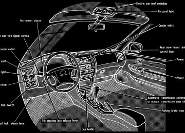
Tilt steering wheel
Outside rear view mirrors—
—Rear view mirror remote control
To change the steering wheel angle, pull up the lock release lever, tilt the steering wheel to the desired angle and release the lever.
CAUTION
(cid:1) Do not adjust the steering wheel
while the vehicle is moving.
(cid:1) After adjusting the steering wheel, try moving it up and down to make sure it is locked in position.
Adjust the mirror so you can see the side of your vehicle in the mirror. Be careful when judging the size or dis- tance of any object seen in the outside rear view mirror on the passenger’s side. It is a convex mirror with a curved surface. Any object seen in a convex mirror will look smaller and farther away than when seen in a flat mirror.
To adjust the rear view mirror, simply operate the control lever.
NOTICE
If ice should jam the mirror, do not operate the control or scrape the mirror face. Use a spray de-icer to free the mirror.
57
—Power rear view mirror control
—Folding rear view mirrors
Anti-glare inside rear view mirror
To fold the rear view mirror, push back- ward. The rear view mirrors can be folded back- ward for parking in restricted areas.
Pull the lever toward you to reduce glare from the headlights of the ve- hicle behind you during night driving. Before adjusting the mirror to the position with most clarity, push the day-night change lever away from you (daylight driving position). Remember that by reducing glare you also lose some rear view clarity.
To adjust a power rear view mirror, first push the master switch in “L” (left) or “R” (right) depending on which mirror needs adjusting, then push the con- trol switch in desired direction. If the engine is not running, the key must be in the “ACC” position. NOTICE
If ice should jam the mirror, do not operate the control or scrape the mirror face. Use a spray de-icer to free the mirror.
58
FIRST CLICKSTOP: Only the parking, tail, license plate, side marker and instru- ment panel lights turn on. SECOND CLICKSTOP: The headlights also turn on. If you remove the key with the headlights left on, a buzzer reminds you to turn the lights off when you open the driver’s door.
NOTICE
To prevent the battery from being discharged, do not leave the lights on for a long period when the engine is not running.
Part 1
OPERATION OF INSTRUMENTS AND CONTROLS—Chapter 1-4
Lights, Wipers and Defogger(cid:1) Headlights and turn signals (cid:1) Emergency flashers (cid:1) Instrument panel light control (cid:1) Interior light (cid:1) Personal light (cid:1) Luggage compartment light (cid:1) Windshield wipers and washer (cid:1) Rear window wiper and washer (cid:1) Rear window defogger
Headlights and turn signals
To turn the lights on, twist the knob on the end of the lever. Daytime running light system (Canada only)—The headlights turn on when the parking brake is released with the engine started, even with the light switch in the “OFF” position. They will not go off until the ignition switch is turned off. To turn on the other exterior lights and in- strument panel lights, twist the knob to the first clickstop. Under the daytime running light system, the headlights turn on at reduced intensi- ty. Twist the knob to the second clickstop to turn to full intensity for driving at night.
59
Emergency flashers
For high beam, push the lever away from you. Pull it toward you for low beam. For the headlight flasher, pull it further back. A blue light in the instrument panel indi- cates high beam is on. The headlight flasher works even when the headlight switch is off.
For signaling turns, move the lever up or down in the conventional manner. The key must be in the ”ON” position. The turn signal is self-cancelling after a turn, but after a lane change, you may have to cancel it by hand. You can also signal a lane change by moving the turn signal lever partway and holding it there. If the green light in the instrument panel flashes faster than normal, it indicates that the front or rear turn signal bulb has burned out.
To turn on the emergency flashers, push the switch. All the turn signal lights will flash. Turn on the emergency flashers to warn other drivers if your vehicle must be stopped where it might be a traffic hazard. Always pull as far off the road as possible. The turn signal light switch will not work when the emergency flashers are operat- ing.
NOTICE
To prevent the battery from being discharged, do not leave the switch on longer than necessary when the engine is not running.
60
Instrument panel light control
Interior light
Personal light
To adjust the brightness of the instru- ment panel lights, turn the dial.
To turn on the interior light, slide the switch. With the switch in the “DOOR” position, the light comes on when any of the side doors and back door are opened.
To turn on the personal light, push the switch. To turn it off, push the switch once again.
61
Luggage compartment light (wagon)
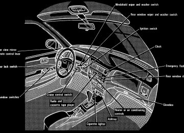
Windshield wipers and washer (intermittent type without interval adjuster)
NOTICE
Do not operate the wipers if the windshield is dry. It may scratch the glass.
To turn the luggage compartment light on, open the back door and push the switch. Closing the back door will turn the light off.
To turn the wipers on, move the lever. To make the washer squirt, push the button on the end of the lever. The key must be in the ”ON” position. The wipers will operate at intervals when the lever is in the ”INT” position. If the washer does not work, check to see whether the washer tank is empty. For in- formation on adding washer fluid, see “Adding washer fluid” in Chapter 7-3. In cold weather, warm the windshield with the defroster before using the washer. This will help prevent icing, which could block your vision.
62
Windshield wipers and washer (intermittent type with interval adjuster)
Windshield wipers and washer (mist type)
If the washer does not work, check to see whether the washer tank is empty. For in- formation on adding washer fluid, see “Adding washer fluid” in Chapter 7-3. In cold weather, warm the windshield with the defroster before using the washer. This will help prevent icing, which could block your vision.
NOTICE
Do not operate the wipers if the windshield is dry. It may scratch the glass.
To turn the wipers on, move the lever. To make the washer squirt, push the button on the end of the lever. The key must be in the “ON” position. The wipers will operate at intervals when the lever is in the “INT” position. With the lever in this position, the wipers can be ad- justed to operate at intervals of 3 to 10 se- conds depending on the interval adjuster setting between “S” and “F”. Also, the wipers will automatically operate a couple of times after the washer squirts even with the lever in the “OFF” position.
To turn the wipers on, move the lever. To make the washer squirt, push the button on the end of the lever. The key must be in the “ON” position. If a single wipe is desired in mist, push the lever to the “MIST” position and release it. If the washer does not work, check to see whether the washer tank is empty. For in- formation on adding washer fluid, see “Adding washer fluid” in Chapter 7-3. In cold weather, warm the windshield with the defroster before using the washer. This will help prevent icing, which could block your vision.
63
Rear window wiper and washer
Rear window defogger
NOTICE
Do not operate the wipers if the windshield is dry. It may scratch the glass.
To defog or defrost the rear window, push the switch. The key must be in the “ON” position. The thin heater wires on the inside of the rear window will quickly clear the sur- faces. An indicator light will illuminate to indicate the defogger is operating. Push the switch once again to turn the de- fogger off. With timer: The system will automatically shut off after the defogger has operated about 15 minutes.
To turn the rear wiper and washer on, twist the knob at the end of the lever. The key must be in the “ON” position. The wipers will operate at intervals when the lever is in the “INT” position. The washer squirts at the two marked knob positions. The knob will automatically re- turn from these positions when it is re- leased. If the washer does not work, check to see whether the washer tank is empty. For in- formation on adding washer fluid, see “Adding washer fluid” in Chapter 7-3.
NOTICE
Do not operate the rear wiper if the rear window is dry. It may scratch the glass.
64
Make sure you turn the defogger off when the window is clear. Leaving the defogger on for a long time could cause the battery to discharge, especially during stop-and- go driving. The defogger is not designed for drying rain water or for melting snow.
NOTICE
(cid:2)Without timer: To prevent the bat- tery from being discharged, turn the switch on when the engine is running.
(cid:2)When cleaning the inside of the rear window, be careful not to scratch or damage the heater wires.
65
66
Part 1
OPERATION OF INSTRUMENTS AND CONTROLS—Chapter 1-5
Gauges, Meters and Service reminder indicators(cid:1) Fuel gauge (cid:1) Engine coolant temperature
gauge
(cid:1) Tachometer (cid:1) Odometer and trip meter (cid:1) Service reminder indicators
and warning buzzers
Fuel gauge
The indicator lamp goes off after driving several times. If the indicator lamp does not go off, contact your Toyota dealer as soon as possible.
The gauge works when the ignition switch is on and indicates the approxi- mate quantity of fuel remaining in the tank. It is a good idea to keep the tank over 1/4
full. This fuel gauge has a non-return type needle which remains at the last indicated position when the ignition switch is turned off. If the fuel level approaches “E” or the low fuel level warning light comes on, fill the fuel tank as soon as possible. If the fuel tank is completely empty, the malfunction indicator lamp comes on. Fill the fuel tank immediately.67
Engine coolant temperature gauge
Tachometer
NOTICE
(cid:2)Do not remove the thermostat in the engine cooling system as this may cause the engine to overheat. The thermostat is designed to control the flow of coolant to keep the temperature of the engine within the specified operating range.
(cid:2)Do not continue driving with an overheated engine. See “If your vehicle overheats” in Part 4.
tachometer
The indicates engine speed in thousands of rpm (revolutions per minute). Use it while driving to se- lect correct shift points and to prevent engine lugging and overrevving. Driving with the engine running too fast causes excessive engine wear and poor fuel economy. Remember, in most cases the slower the engine speed, the greater the fuel economy.
NOTICE
Do not let the indicator needle get into the red zone. This may cause severe engine damage.
The gauge indicates the engine cool- ant temperature when the ignition switch is on. The engine operating temperature will vary with changes in weather and engine load. If the needle points to the red zone or high- er, stop your vehicle and allow the engine to cool. Your vehicle may overheat during severe operating conditions, such as: (cid:1) Driving up a long hill on a hot day. (cid:1) Reducing speed or stopping after high
speed driving. Idling for a long period with the air con- ditioning on in stop-and-go traffic.
(cid:1)
(cid:1) Towing a trailer.
68
Odometer and trip meter
Service reminder indicators and warning buzzers
The odometer records the total dis- tance the vehicle has been driven. The trip meter may be set to zero to record the distance on each trip. To reset the trip meter, press the trip meter reset knob. The black digits on white indicate tenths of kilometers or miles.
69
If the brake fluid level is correct... Have the warning system checked by your Toyota dealer. (b) Seat Belt Reminder Light and Buzzer Once the ignition key is turned to “ON” or “START”, the reminder light and buzzer come on if the driver’s seat belt is not fas- tened. Unless the driver fastens the belt, the light stays on and the buzzer stops af- ter about 4 to 8 seconds. (c) Discharge Warning Light This light warns that the battery is being discharged. If it comes on while you are driving, there is a problem somewhere in the charging system. The engine ignition will continue to operate, however, until the battery is discharged. Turn off the air conditioning, blower, radio, etc., and drive directly to the nearest Toyota dealer or repair shop.
NOTICE
Do not continue driving if the engine drive belt is broken or loose.
(d) Low Oil Pressure Warning Light This light warns that the engine oil pres- sure is too low. If it flickers or stays on while you are driv- ing, pull off the road to a safe place and stop the engine immediately. Call a Toyota dealer or qualified repair shop for assis- tance. The light may occasionally flicker when the engine is idling or it may come on brief- ly after a hard stop. There is no cause for concern if it then goes out when the en- gine is accelerated slightly. The light may come on when the oil level is extremely low. It is not designed to indi- cate low oil level, and the oil level must be checked using the level dipstick.
NOTICE
Do not drive the vehicle with the warning light on—even for one block. It may ruin the engine.
(e) Low Fuel Level Warning Light This light comes on when the fuel level in the tank becomes nearly empty. Fill up the tank as soon as possible.
(a) Brake System Warning Light This light has the following functions: Parking brake reminder If this light is on, make sure the parking brake is fully released. The light should go off. Low brake fluid level warning If this light comes on and stays on while you are driving, slow down and pull off the road. Then stop the vehicle carefully. There may be a problem somewhere in the brake system. Check the fluid level of the see-through reservoir. To make sure the parking brake has not caused the warning light to come on, check to see that the parking brake is fully released. If the brake fluid level is low... At a safe place, test your brakes by start- ing and stopping.
(cid:1)
(cid:1)
If you judge that the brakes still work adequately, drive cautiously to your nearest dealer or shop for repairs. If the brakes are not working, have the vehicle towed in for repairs. (For tow- ing information, see Part 4.)
CAUTION
It is dangerous to continue driving normally when the brake fluid level is low.
70
(f) “ABS” Warning Light This light warns that there is a problem somewhere in your anti-lock brake sys- tem. If the light comes on while you are driving, have your vehicle checked by your Toyota dealer as soon as possible. The light will come on when the ignition key is turned to the “ON” position. After about 3 seconds, the light will go off. When the “ABS” warning light is on (and the brake system warning light is off), the brake system operates conventionally but without anti-lock function. (g) Open Door Warning Light This light remains on until all the side doors and back door are completely closed. (h) SRS Airbag Warning Light This light will come on when the igni- tion key is turned to the “ACC” or “ON” position. After about 6 seconds, the light will go off. This means the airbag system is operating properly. The warning light system monitors the air- bag sensor assembly, inflators, warning light, interconnecting wiring and power sources.
If either of the following conditions occurs, this indicates a malfunction somewhere in the parts monitored by the warning light system. Contact your Toyota dealer as soon as possible to service the vehicle. (cid:1) The light does not come on when the ignition key is turned to the “ACC” or “ON” position or remains on.
(cid:1) The light comes on while driving. (i) Malfunction Indicator Lamp This lamp comes on in the following cases. a. The fuel tank is completely empty. (See “Fuel gauge” in Chapter 1-5 for in- structions.) b. There is a problem somewhere in your engine or automatic transmission electri- cal system. If it comes on while you are driving in case b, have your vehicle checked/repaired by your Toyota dealer as soon as possible. (j) Key Reminder Buzzer This buzzer reminds you to remove the key when you open the driver’s door with the ignition key in the “ACC” or “LOCK” position.
(k) Light Reminder Buzzer This buzzer will sound if the driver’s door is opened with the key removed from the ignition switch and the headlight switch left on. CHECKING SERVICE REMINDER INDI- CATORS (except the low fuel level warning light) 1. Apply the parking brake. 2. Open one of the side doors or back door. The open door warning light should come on. 3. Close the door. The open door warning light should go off. 4. Turn the ignition key to “ACC”. The SRS airbag warning light should come on. It goes off after about 6 sec- onds. 5. Turn the ignition key to “ON”, but do not start the engine. All the service reminder indicators except the open door warning light and SRS air- bag warning light should come on. The “ABS” warning light goes off after about 3
seconds. If any service reminder indicators or warn- ing buzzer do not function as described above, either the bulb is burned out or the circuit is in need of repair. Have it checked by your Toyota dealer as soon as pos- sible.71
72
Part 1
OPERATION OF INSTRUMENTS AND CONTROLS—Chapter 1-6
Ignition switch, Transmission and Parking brake(cid:1) Ignition switch with steering lock (cid:1) Automatic transmission (cid:1) Manual transmission (cid:1) Parking brake (cid:1) Cruise control
Ignition switch with steering lock
“Start”—Starter motor on. The key will return to the “ON” position when re- leased. For starting tips, see Part 3. “ON”—Engine on and all accessories on. This is the normal driving position. “ACC”—Accessories such as the radio operate, but the engine is off. If you leave the key in the “ACC” or “LOCK” position and open the driver’s door, a buzzer will remind you to remove the key.
“LOCK”—Engine is off and the steer- ing wheel is locked. The key can be re- moved only at this position. You must push in the key to turn the key from “ACC” to the “LOCK” position. On vehicles with an automatic transmission, the selector lever must be in the “P” posi- tion before pushing the key. When starting the engine, the key may seem stuck at the “LOCK” position. To free it, first be sure the key is pushed all the way in, and then rock the steering wheel slightly while turning the key gently.
CAUTION
For manual transmission:
Never remove the key when the ve- hicle is moving, as this will lock the steering wheel and result in loss of steering control.
NOTICE
Do not leave the key in the “ON” position if the engine is not running. The battery will discharge and the ignition could be damaged.
73
Automatic transmission (3-speed type)
Your automatic transmission has a shift lock system to minimize the possibility of incorrect operation. This means you can only shift out of “P” position when the brake pedal is depressed (with the ignition switch in “ON” position and the lock re- lease button depressed). (a) Normal Driving 1. Start the engine as instructed in “How to start the engine” in Part 3. The trans- mission must be in “P” or “N”. 2. With your foot holding down the brake pedal, shift the selector lever to “D”. In “D” position, the automatic transmis- sion system will select the most suitable gear for running conditions such as nor- mal cruising, hill climbing, hard towing, etc.
CAUTION
(b) Using engine braking To use engine braking, you can downshift the transmission as follows: (cid:1) Shift into the “2” position when the ve- hicle speed is lower than the maximum allowable speed for second gear. The transmission will downshift to the sec- ond gear and more engine braking will be obtained.
(cid:1) Shift into the “L” position when the ve- hicle speed is lower than the maximum allowable speed for “L” position. The transmission will downshift to the first gear and maximum engine braking will be applied.
MAXIMUM ALLOWABLE SPEEDS “2” “L”
. . . . . . . . . . . . . . . . . . . . . . . . .
112 km/h (70 mph) 62 km/h (38 mph)
Never put your foot on the accelera- tor pedal while shifting. 3. Release the parking brake and brake pedal. Depress the accelerator pedal slowly for smooth starting.
CAUTION
Be careful when downshifting on a slippery surface. Abrupt shifting could cause the vehicle to spin or skid.
74
Automatic transmission (4-speed type)
NOTICE
(cid:2)Be careful not to overrev the en- gine. Watch the tachometer to keep engine rpm from going into the red zone. The maximum allow- able speed (approximate) for each position is given above for your reference.
(cid:2)Do not continue hill climbing for a long time in the “2” or “L” position. This may cause severe automatic transmission damage from over- heating. To prevent such damage, use “D” position for hill climbing or hard towing.
(c) Backing up 1. Bring the vehicle to a complete stop. 2. With the brake pedal held down with your foot, shift the selector lever to the “R” position.
NOTICE
Never shift into reverse while the vehicle is moving.
(d) Parking 1. Bring the vehicle to a complete stop. 2. Pull the parking brake lever up fully to securely apply the parking brake. 3. With the brake pedal pressed down, shift the selector lever to the “P” position.
CAUTION
While the vehicle is moving, never attempt to move the selector lever into “P” position under any circum- stances. Serious mechanical dam- age and loss of vehicle control may result.
(e) Good driving practice
CAUTION
Always keep your foot on the brake pedal while stopped with the engine running. This prevents the vehicle from creeping.
NOTICE
Do not hold the vehicle on an upgrade with the accelerator pedal. It can cause the transmission to overheat. Always use the brake pedal or parking brake. (f) If you cannot shift the selector lever
out of “P” position
If you cannot shift the selector lever from “P” position even though the brake pedal is depressed, use the shift lock override button. For instructions, see “If you can- not shift automatic transmission selector lever” in Part 4.
75
Your automatic transmission has a shift lock system to minimize the possibility of incorrect operation. This means you can only shift out of “P” position when the brake pedal is depressed (with the ignition switch in “ON” position and the lock re- lease button depressed). (a) Normal Driving 1. Start the engine as instructed in “How to start the engine” in Part 3. The trans- mission must be in “P” or “N”. 2. With your foot holding down the brake pedal, shift the selector lever to “D”. In “D” position, the automatic transmis- sion system will select the most suitable gear for running conditions such as nor- mal cruising, hill climbing, hard towing, etc. Always turn the overdrive switch on for better fuel economy and quieter driving. If the engine coolant temperature is low, the transmission will not shift into the over- drive gear even with the overdrive switch on.
CAUTION
Never put your foot on the accelera- tor pedal while shifting.
3. Release the parking brake and brake pedal. Depress the accelerator pedal slowly for smooth starting.
76
(b) Using engine braking To use engine braking, you can downshift the transmission as follows: (cid:1) Turn off the overdrive switch. The “O/D OFF” indicator light will come on and the transmission will downshift to the third gear.
(cid:1) Shift into the “2” position. The trans- mission will downshift to the second gear when the vehicle speed drops down to or lower than the maximum al- lowable speed for second gear, and more powerful engine braking will be obtained.
(cid:1) Shift into the “L” position. The trans- mission will downshift to the first gear when the vehicle speed drops down to or lower than the maximum allowable speed for “L” position and maximum engine braking will be applied.
MAXIMUM ALLOWABLE SPEEDS “2” “L”
. . . . . . . . . . . . . . . . . . . . . . . . .
110 km/h (68 mph) 60 km/h (38 mph)
(d) Parking 1. Bring the vehicle to a complete stop. 2. Pull the parking brake lever up fully to securely apply the parking brake. 3. With the brake pedal pressed down, shift the selector lever to the “P” position.
CAUTION
While the vehicle is moving never attempt to move the selector lever into “P” position under any circum- stances. Serious mechanical da- mage and loss of vehicle control may result.
(e) Good driving practice
(cid:1)
If the transmission is repeatedly up- shifted and downshifted between third gear and overdrive when climbing a gentle slope, the overdrive switch should be turned off. Be sure to turn the switch on immediately afterward. (cid:1) When towing a trailer, in order to main- tain engine braking efficiency, do not use overdrive.
CAUTION
Always keep your foot on the brake pedal while stopped with the engine running. This prevents the vehicle from creeping.
NOTICE
Do not hold the vehicle on an upgrade with the accelerator pedal. It can cause the transmission to overheat. Always use the brake pedal or parking brake.
(f) If you cannot shift the selector lever
out of “P” position
If you cannot shift the selector lever from “P” position even though the brake pedal is depressed, use the shift lock override button. For instructions, see “If you can- not shift automatic transmission slelector lever” in Part 4.
CAUTION
Be careful when downshifting on a slippery surface. Abrupt shifting could cause the vehicle to spin or skid.
NOTICE
(cid:2)Be careful not to overrev the en- gine. Watch the tachometer to keep engine rpm from going into the red zone. The maximum allowable speed (approximate) for each posi- tion is given above for your refer- ence.
(cid:2)Do not continue hill climbing for a long time in the “2” or “L” position. This may cause severe automatic trasmission damage from over- heating. To prevent such damage, use “D” position for hill climbing or hard towing.
(c) Backing up 1. Bring the vehicle to a complete stop. 2. With the brake pedal held down with your foot, shift the selector lever to the “R” position.
NOTICE
Never shift into reverse while the vehicle is moving.
77
Manual transmission
For the best compromise between fuel economy and vehicle performance, you should upshift or downshift at the follow- ing speeds:
Low altitude —1219 m (4000 ft) or lower
km/h (mph)
24 (15) 37 (23)
gear
1 to 2 or 2 to 1
2 to 3 or 3 to 2
3 to 4 or 4 to 3
4 to 5 or 5 to 4*1: For
constant-speed
64/45*1 (40/28*1) 72/64*1 (45/40*1) cruise or constant-speed cruise after decel- eration. High altitude —Higher than 1219 m (4000 ft)
Upshifting
gear 1 to 2
2 to 3
3 to 4
4 to 5Downshifting
gear 2 to 1
3 to 2
4 to 3
5 to 4km/h (mph)
24 (15)
40/57*2
64/72*2
72/88*2(25/36*2) (40/45*2) (45/55*2)
km/h (mph)
24 (15) 40 (25) 64 (40) 72 (45)
*2: 4A-FE only—Applicable under heavy
acceleration conditions.
The shift pattern is conventional as shown above. Press the clutch pedal down fully while shifting, and then release it slowly. Do not rest your foot on the pedal while driving, because it will cause clutch trouble. And do not use the clutch to hold the vehicle when stopped on an uphill grade—use the parking brake. Recommended shifting speeds The transmission is fully synchronized and upshifting or downshifting is easy.
78
Upshifting too soon or downshifting too late will cause lugging, and possibly pinging. Regularly revving the engine to maximum speed in each gear will cause excessive engine wear and high fuel comsumption. Maximum allowable speeds To get on a highway or to pass slower traf- fic, maximum acceleration may be neces- sary. Make sure you observe the following maximum allowable speeds in each gear: 4A-FE engine
gear
7A-FE engine
gear
km/h (mph) 46 (29) 86 (54) 126 (78) 170 (106)
km/h (mph) 53 (33) 88 (55) 128 (80) 173 (108)
NOTICE
Do not downshift if you are going faster than the maximum allowable speed for the next lower gear.
Good driving practice
(cid:1)
If it difficult to shift into reverse, put the transmission in neutral, release the clutch pedal momentarily, and then try again.
(cid:1) When towing a trailer, in order to main- tain engine braking efficiency, do not use the fifth gear.
CAUTION
Be careful when downshifting on a slippery surface. Abrupt shifting could cause the vehicle to spin or skid.
NOTICE
Make sure the vehicle is completely stopped before shifting into reverse.
Parking brake
Cruise control
To set: Pull up the lever. To release: Pull up slightly, press the thumb button, and lower. Before leaving your vehicle, firmly apply the parking brake. For better holding pow- er, first depress the brake pedal and hold it while setting the parking brake.
CAUTION
Before driving, be sure the parking brake is fully released and the park- ing brake reminder light is off.
The cruise control allows you to cruise the vehicle at a desired speed over 40
km/h (25 mph) even with your foot off the accelerator pedal. Your cruising speed can be maintained up or down grades within the limits of engine performance, although a slight speed change may occur when driving up or down the grades. On steeper hills, a greater speed change will occur so it is better to drive without the cruise control.79
CAUTION
(cid:1) To help maintain maximum control of your vehicle, do not use the cruise control when driving in heavy or varying traffic, or on slip- pery (rainy, icy or snow-covered) or winding roads.
(cid:1) Avoid vehicle speed
increases when driving downhill. If the ve- hicle speed is too fast in relation to the cruise control set speed, can- cel the cruise control then down- shift the transmission to use en- gine braking to slow down.
TURNING ON THE SYSTEM To operate the cruise control, push the “CRUISE ON-OFF” switch. This turns the system on. The indicator light in the instru- ment panel shows that you can now set the vehicle at a desired cruising speed. Another push will turn the system com- pletely off.
CAUTION
To avoid accidental cruise control engagement, keep the “CRUISE ON- OFF” switch off when not using the cruise control.
80
If the vehicle speed falls below about 40
km/h (25 mph), the preset speed will auto- matically cancel out. If the vehicle speed drops 16 km/h (10
mph) below the preset speed, the preset speed will also automatically cancel out. If the preset speed automatically cancels out other than for the above cases, have your vehicle checked by your Toyota deal- er at the earliest opportunity. RESETTING AT A FASTER SPEED Press the control lever upward in the “RES/ACC” direction and hold it. Release the lever when the desired speed is at- tained. While the lever is held upward, the vehicle will gradually gain speed. However, a faster way to reset is to accel- erate the vehicle and then press the lever downward in the “SET/COAST” direction. RESETTING AT A SLOWER SPEED Push the control lever downward in the “SET/COAST” direction and hold it. Re- lease the lever when the desired speed is attained. While the lever is held down- ward, the vehicle speed will gradually de- crease.SETTING AT A DESIRED SPEED On vehicles with automatic transmission, the transmission must be in “D” before you set the cruise control speed. Bring your vehicle to the desired speed, press the “SET/COAST” direction and re- lease it. This sets the vehicle at that speed. Now you may take your foot off the accelerator pedal. If you need accelera- tion—for example, when passing—de- press the accelerator pedal enough for the vehicle to exceed the set speed. When you release it, the vehicle will return to the speed set prior to the acceleration.
CAUTION
For manual transmission:
While driving with the cruise control on, do not shift to neutral without depressing the clutch pedal, as this may cause engine racing or overrev- ing.
CANCELLING THE PRESET SPEED You can cancel the preset speed by: a. Pulling the control lever in the “CAN- CEL” direction and releasing it. b. Depressing the brake pedal. c. Depressing the clutch pedal (manual transmission).
However, a faster way to reset is to de- press the brake pedal and then press the control lever downward in the “SET/ COAST” direction. RESUMING THE PRESET SPEED If the preset speed is cancelled by pulling the control lever or by depressing the brake pedal or clutch pedal, pushing the lever up in the “RES/ACC” direction will restore the speed set prior to cancellation. However, once the vehicle speed falls be- low about 40 km/h (25 mph), the preset speed will not be resumed. CRUISE CONTROL FAILURE WARNING If the “CRUISE” indicator light in the in- strument cluster flashes when using the cruise control, there is some trouble in the cruise control system. Contact your Toyo- ta dealer and have your vehicle inspected.
81
82
Part 1
OPERATION OF INSTRUMENTS AND CONTROLS—Chapter 1-7
Car audio system and Air conditioning system(cid:2) Car audio system operating tips (cid:2) AM-FM radio with electronic
tuner
(cid:2) AM-FM radio with electronic
tuner and cassette tape player
(cid:2) Air conditioning controls (cid:2) Heater controls (cid:2) Side vents
Car audio system operating tips You can listen to the car audio system when the ignition key is at “ON” or “ACC”. However, if the engine is not running, the key must be in the “ACC” position. ILLUMINATION CONTROL LOGIC On some audio-units, when the instru- ment panel lights are on, the letters on op- erable buttons of the mode in current use light up together with the mode selection and eject buttons. RADIO FM reception tips Most of us are not aware that a vehicle is not an ideal place to listen to a radio. Be- cause it moves, reception conditions change continuously. Buildings, terrain, signal distance and noise from other ve- hicles are all working against good recep- tion. Some FM reception conditions may appear to be problems even though they are normal. The following characteristics are normal for a given reception area, and they do not indicate any problem with the radio itself. (cid:2) Fading and Drifting: On the average, the broadcast range of FM stations is limited to about 40 km (25 miles), ex- cept for some high power stations.
If a vehicle is moving away from the desired station’s transmitter, the signal will tend to fade and/or drift. This phe- nomenon is more noticeable with FM than with AM, and is accompanied by distortion. Fading and drifting can be minimized to a certain degree by fine tuning, or you should tune in to a stronger signal. (cid:2) Static and Fluttering: When the line- of-sight path between a transmitter and vehicle is blocked by large build- ings or the like, static or fluttering may occur because of the characteristic of FM. In a similar effect, a fluttering noise is sometimes heard when driv- ing along a tree-lined road. This static and fluttering can be re- duced by adjusting the tone control for greater bass response until the distur- bance has passed.
(cid:2) Multipath: Because of the reflection characteristics of FM, direct and re- flected signals may reach the antenna at the same time (a phenomenon called multipath reception) and cancel each other out. As a vehicle moves through these electronic dead spots, the listener may hear a momentary flutter or lose reception.
83
NOTICE
Do not oil any part of the player and do not insert anything other than cassette tapes into the slot, or the tape player may be damaged.
CASSETTE TAPE PLAYER Use only undamaged cassette tapes of good quality. Avoid using tapes with a total playing time longer than 90 min- utes. Using damaged tapes will cause trouble with the tape player. Longer tapes are not recommended because of their thinness. Before inserting a cassette, make sure the tape is not slack and that the label is firmly stuck on the shell. Wind the tape firmly by turning the hub with a pencil or the like. Be careful not to touch the exposed tape surface. When not in use, take the cassette out of the player, put it back into its case and store it away from dust, magnets and direct sunlight. Leaving cassettes on the dashboard in the sun could damage your tapes. Keep the playback head, capstan and pinch roller clean. Remove tape coating residue accumu- lated on the head, capstan and pinch roll- er once or twice a month. A cleaning tape is available on the market.
(cid:2) Station swapping: When two FM sta- tions are close to each other, and an electronic dead spot, such as is caused by static or multipath recep- tion, interrupts the original signal, sometimes the stronger second signal is picked up automatically until the original one returns. This swapping can also occur as you drive away from the selected station and approach another station with a stronger signal. On models with a power antenna, the an- tenna automatically extends to its full height when the radio and ignition are turned on. To lower the power antenna, turn off the audio system by pushing “PWR.VOL”, or turn the ignition key to “LOCK”. On some models, the power antenna au- tomatically retracts when the radio mode is switched off to turn on the cassette tape player. Before extending the power antenna, confirm that no one is close enough to get injured by it.
NOTICE
To prevent damage to the antenna, make sure it is retracted before driving your vehicle through an automatic car wash.
84
AM(cid:2)FM radio with electronic tuner (type A)
85
(a) Listening to the radio 1. Push the “PWR(cid:2)VOL” knob to turn the radio on. 2. Turn the “PWR(cid:2)VOL” knob to adjust the volume. 3. Tune in the desired station. (See “(b) Selecting a station” and “(c) Presetting a station”.) The radio will change automatically to ste- reo reception when an FM stereo broad- cast is being received. At the same time, “ST” will appear on the display. When the receiving signal gets weak, the channel separation will automatically be reduced for the lowest noise. If the signal becomes extremely weak, the radio will switch over to monaural reception. 4. Adjust the tone and sound balance. (See “(d) Adjusting the tone” and “(e) Ad- justing the sound balance”.) 5. To “PWR(cid:2)VOL” knob once again. (b) Selecting a station 1. Push the “AM(cid:2)FM” button to select ei- ther an AM or FM broadcast. “AM” or “FM” will appear on the display. 2. Tune in the desired station using one of the following methods. The frequency will appear on the display.
the radio off, push
turn
the
Each button can store one AM station and one FM station. To change the preset sta- tion to a different one, follow the same pro- cedure. The preset station will be cancelled when the power source is severed (battery dis- connected, burnt fuse, etc.). (d) Adjusting the tone Turn the “TONE” knob. (e) Adjusting the sound balance Turn the “BAL” knob.
Preset tuning: Use for tuning-in to a de- sired preset station. Push the station selector button which has been preset to the desired station. The radio will tune in to the station and the button number will appear on the display. (See “(c) Presetting a station”.) Seek tuning: Use for automatic station search and stop. Push either side of the “TUNE” button and hold it until a beep is heard. The radio will begin seeking up or down for a station of the nearest frequency and will stop on re- ception. Each time you push the button, stations will be sought out one after anoth- er. Manual tuning Push either side of the “TUNE” button for less than 0.5 second. Each time you push the button, the radio will step up or down to another frequency where stations could exist. (c) Presetting a station 1. Tune in the desired station. (See “(b) Selecting a station”.) 2. Push one of the station selector but- tons and hold it until a beep is heard. This sets the station to the button and the but- ton number will appear on the display.
86
AM(cid:2)FM radio with electronic tuner (type B)
87
(a) Listening to the radio 1. Push the “PWR(cid:2)VOL” knob to turn the radio on. 2. Turn the “PWR(cid:2)VOL” knob to adjust the volume. 3. Tune in the desired station. (See “(b) Selecting a station” and “(c) Presetting a station”.) The radio will change automatically to ste- reo reception when an FM stereo broad- cast is being received. At the same time, “ST” will appear on the display. When the receiving signal gets weak, the channel separation will automatically be reduced for the lowest noise. If the signal becomes extremely weak, the radio will switch over to monaural reception. 4. Adjust the tone and sound balance. (See tone” and “(e) Adjusting the sound balance”.) 5. To “PWR(cid:2)VOL” knob once again. (b) Selecting a station 1. Push the “AM(cid:2)FM” button to select ei- ther an AM or FM broadcast. “AM” or “FM” will appear on the display. 2. Tune in the desired station using one of the following methods. The frequency will appear on the display.
the radio off, push
“(d) Adjusting
turn
the
the
Preset tuning: Use for tuning-in to a de- sired preset station. Push the station selector button which has been preset to the desired station. The radio will tune in to the station and the button number will appear on the display. (See “(c) Presetting a station”.) Seek tuning: Use for automatic station search and stop. Push either side of the “TUNE” button and hold it until a beep is heard. The radio will begin seeking up or down for a station of the nearest frequency and will stop on re- ception. Each time you push the button, sta- tions will be sought out one after another. Scan tuning: Use for station-to-station scanning. Push the “SCAN” button. With “SCAN” on the display, the radio will automatically seek out a station of a higher frequency, hold it for 5 seconds and scan to the next. To continue listening to the broadcast of your choice, simply push the “SCAN” but- ton once again. Manual tuning Push either side of the “TUNE” button for less than 0.5 second. Each time you push the button, the radio will step up or down to another frequency where stations could exist.
(c) Presetting a station 1. Tune in the desired station. (See “(b) Selecting a station”.) 2. Push one of the station selector but- tons and hold it until a beep is heard. This sets the station to the button and the button number will appear on the display. Each button can store one AM station and one FM station. To change the preset sta- tion to a different one, follow the same pro- cedure. The preset station will be cancelled when the power source is severed (battery dis- connected, burnt fuse, etc.). (d) Adjusting the tone To adjust a low-pitched tone, push the “BASS TREB” knob (if pushed in) and turn it. To adjust a high-pitched tone, push the “BASS TREB” knob (if pushed in), pull it fully out and turn it. (e) Adjusting the sound balance To balance the sound between the right and left speakers, push the “BAL FADE” knob (if pushed in) and turn it. To balance the sound between the front and rear speakers, push the “BAL FADE” knob (if pushed in), pull it fully out and turn it.
88
AM(cid:2)FM radio with electronic tuner and cassette tape player
89
90
(a) Listening to the radio 1. Push the “AM(cid:2)FM” button to turn the radio on and select either an AM or FM broadcast. “AM” or “FM” will appear on the display. The radio can also be turned on by push- ing the “PWR VOL” knob if the radio was on when the system was turned off. 2. Turn the “PWR VOL” knob to adjust the volume. 3. Tune in the desired station. (See “(b) Selecting a station” and “(c) Presetting a station”.) The radio will change automatically to ste- reo reception when an FM stereo broad- cast is being received. At the same time, “ST” will appear on the display. When the receiving signal gets weak, the channel separation will automatically be reduced for the lowest noise. If the signal becomes extremely weak, the radio will switch over to monaural reception. 4. Adjust the tone and sound balance. (See “(d) Adjusting the tone” and “(e) Ad- justing the sound balance”.) 5. To turn the radio off, push the “PWR VOL” knob.
(b) Selecting a station Tune in the desired station using one of the following methods. The frequency will appear on the display. Preset tuning: Use for tuning-in to a de- sired preset station. (See “(c) Presetting a station”.) Push the station selector button which has been preset to the desired station. The radio will tune in to the station and the button number will appear on the display. Seek tuning: Use for automatic station search and stop. Push the “TUNE (REW FF)” button on ei- ther side and hold it until a beep is heard. The radio will begin seeking up or down for a station of the nearest frequency and will stop on reception. Each time you push the button, stations will be sought out one af- ter another. Scan tuning: Use for station-to-station scanning. Scanning for all frequencies—Push the “SCAN” button and hold it until a beep is heard. With “SCAN” on the display, the ra- dio will automatically seek out a station of a higher frequency, hold it for 5 seconds and scan to the next. To continue listening to the broadcast of your choice, simply push the “SCAN” button once again.
If the radio scans over all frequencies without stop because the signals are too weak or just because you leave it going, the radio will begin scanning again with sensitivity boosted for searching out weak stations. Scanning for preset stations—Push the “SCAN” button within 2 seconds. With “SCAN” on the display, the radio will auto- matically seek out a preset station, hold it for 5 seconds and scan to the next. To continue listening to the station of your choice, simply push the “SCAN” button once again. Manual tuning Push the “TUNE (REW FF)” button on ei- ther side for less than 0.5 second. Each time you push the button, the radio will step up or down to another frequency where stations could exist. (c) Presetting a station 1. Tune in the desired station. (See “(b) Selecting a station”.) 2. Push one of the station selector but- tons and hold it until a beep is heard. This sets the station to the button and the but- ton number will appear on the display. Each button can store one AM station and one FM station. To change the preset sta- tion to a different one, follow the same pro- cedure.
91
The preset station will be cancelled when the power source is severed (battery dis- connected, burnt fuse, etc.). (d) Adjusting the tone To adjust a low-pitched tone, push the “BASS TREB” knob (if pushed in) and turn it. To adjust a high-pitched tone, push the “BASS TREB” knob (if pushed in), pull it fully out and turn it. (e) Adjusting the sound balance To balance the sound between the right and left speakers, pull the “BAL” knob and turn it. To balance the sound between the front and rear speakers, turn the “FADE” knob. (f) Listening to the cassette tape 1. Put the cassette into the slot, with the tape side to the right and lightly push it in. The tape player will grab the cassette and slide it into place to play it. If the radio is on when inserting the cassette, the radio will automatically turn off. If the cassette is already in the slot, push the “TAPE” button. At this time, “PLAY” will appear on the dis- play.
The tape player can also be turned on by pushing the “PWR VOL” knob if the tape player was playing when the system was turned off by pushing the knob. 2. If using a tape recorded with Dolby(cid:1) NR*, push the button marked with the double-D symbol. The display will indi- cate that the Dolby noise reduction sys- tem is on. The Dolby NR mode reduces tape noise by about 10 dB. For best sound reproduc- tion, play your tapes with the Dolby(cid:1) NR* on or off according to the mode used for recording the tape. To play a tape recorded without Dolby(cid:1) NR*, push the button again to turn off the Dolby(cid:1) NR*. *: Dolby noise reduction manufactured under license from Dolby Laboratories Licensing Corporation. “DOLBY” and the double-D symbol are trademarks of Dolby Laboratories Licensing Corpo- ration.
3. Turn the “PWR VOL” knob to adjust the volume. 4. Select your program. (See “(g) Select- ing a program”.) 5. Adjust the tone and sound balance. (See “(d) Adjusting the tone” and “(e) Ad- justing the sound balance”.)
6. To turn the player off, push the “PWR VOL” knob. 7. To eject the cassette, push the EJECT button. As this is done, the player will turn off. If the radio was on when the cassette tape was inserted, it will automatically turn on again. You can eject the cassette only once after the system is turned off. (g) Selecting a program 1. Push the “PROG” button to select a side to play. The tape operation indicator display shows you which side is being played. The player will automatically reverse di- rections at the end of the tape to play the other side. 2. Push the “REW FF (TUNE)” button on either side to fast forward or rewind the tape. At this time, “FF” or “REW” will ap- pear on the display. To stop the tape while it is fast forwarding, push “FF” or “TAPE”; to stop the tape while it is rewinding, push “REW” or “TAPE”. The tape will immedi- ately begin to play.
92
Air conditioning controls
93
(a) Controls and functions The temperature control lever is used to adjust the temperature of the delivered air. Move the lever toward the HIGH position for higher temperature and toward the LOW position for lower temperature. The air intake control lever is used to se- lect intake air, either outside air or recircu- lated air. With the lever in the OUTSIDE AIR posi- tion, the system will take fresh outside air- into the unit. For recirculated air, move the lever to the RECIRCULATED AIR posi- tion. The air flow control lever is used to select the air flow outlets air is delivered from. See “(f) Air flow selection” for detailed in- formation. The fan speed control lever is used to turn on and off the fan and select the fan speed. The higher the fan speed setting is, the more air is delivered. Moving the lever to the “OFF” position turns off the fan. The air conditioning on-off button is used to turn on and off the air conditioning. With the button pressed in, the air condi- tioning turns on. Pressing the button once again will turn the air conditioning off.
94
If the indicator light flashes, contact your Toyota dealer as soon as possible. There may be a slippage of the drive belt or trouble in the compressor. If this happens, the air conditioning is automatically turned off to avoid damage to the drive belt. (b) Heating 1. Place the temperature control lever anywhere except the LOW position. When dehumidified heating is desired, place the lever between the HIGH and middle positions. If cooler air is desired at face level for bi- level operation, place the lever around the middle. 2. Move the air intake control lever to the OUTSIDE AIR position. If quick circulation of heated air is desired, move the lever to the RECIRCULATED AIR position. For normal use, it is best to keep the lever in the OUTSIDE AIR position. Otherwise the windows will fog up more easily. 3. Move the air flow control lever to the FLOOR position. If cooler air is desired at face level for bi- level operation, place the lever to the BI- LEVEL position.
If the windshield fogs up easily, move the lever to the FLOOR/WINDSHIELD posi- tion. For detailed information on air flow control including other settings, see “(f) Air flow selection”. 4. Move fan speed control lever any- where except the “OFF” position. 5. Leave the air conditioning on-off but- ton in the ”OFF” position. If dehumidifed heating is desired, press in the air conditioning on-off button. (c) Cooling 1. Place the temperature control lever anywhere between the middle and LOW positions. If warmer air is desired at floor level for bi- level operation, place the lever around the middle. 2. Move the air intake control lever to the OUTSIDE AIR position. If quick circulation of cooled air is desired, move the lever to the RECIRCULATED AIR position. For normal use, it is best to keep the lever in the OUTSIDE AIR position.
3. Move the air flow control lever to the FACE position. If warmer air is desired at floor level for bi- level operation, place the lever to the BI- LEVEL position. For detailed information on air flow control including other settings, see “(f) Air flow selection”. 4. Move the fan speed control lever any- where except the “OFF” position. 5. Press in the air conditioning on-off but- ton. (d) Ventilation 1. Place the temperature control lever at the LOW position. 2. Move the air intake control lever to the OUTSIDE AIR position. 3. Move the air flow control lever to the FACE position. For detailed information on air flow control including other settings, see “(f) Air flow selection”. 4. Move the fan speed control lever any- where except the “OFF” position. 5. Leave the air conditioning on-off but- ton in the “OFF” position.
95
(f) Air flow selection FACE position—This position directs the air flow to face level. BI-LEVEL—This position directs the air flow to face level and floor. Except in ven- tilation, the air to the floor is slightly warm- er than that to the face level. FLOOR position—This position directs the air flow mostly to the floor. FLOOR / WINDSHIELD position — This position directs the air flow to the wind- shield and front side windows as well as the floor. WINDSHIELD position—This position di- rects the air flow mostly to the windshield, front side windows. Do not use the WINDSHIELD position during cooling operation in extremely hu- mid weather. The difference between the temperature of the outside air and that of the windshield could cause the outer sur- face of the windshield to fog up blocking your vision. (g) Operating tips (cid:1) Be sure the air inlet grilles in front of the windshield are not blocked by leaves or other obstructions.
(cid:1)
If air flow control is not satisfactory, check the side vents. (See “Side vents” after “Heater controls”.)
(cid:1) To help cool down the interior after parking in the hot sun, drive for the first few minutes with the windows open. After the excess heat has blown away, close the windows.
(cid:1) When driving on dusty roads, close all windows. If dust thrown up by the ve- hicle is still drawn into the vehicle after closing the windows, it is recom- mended that the air intake control le- ver be set to the OUTSIDE AIR posi- tion and the fan speed control lever anywhere except the “OFF” position. If following another vehicle on a dusty road, or driving in windy and dusty con- ditions, it is recommened that the air intake control lever be temporarily set to the RECIRCULATED AIR position, which will close off the outside pas- sage and prevent outside air and dust from entering the vehicle interior.
(cid:1)
(e) Windshield defogging and defrost-
ing
To remove interior fog on the windshield: 1. Place the temperature control lever at any position. 2. Move the air intake control lever to the OUTSIDE AIR position. 3. Move the air flow control lever to the WINDSHIELD position. For detailed information on air flow con- trol, see “(f) Air flow selection”. 4. Move fan speed control lever any- where except the “OFF” position. 5. Press in the air conditioning on-off but- ton. To remove frost or exterior fog on the windshield: 1. Place the temperature control lever at the HIGH position. 2. Move the air intake control lever to the OUTSIDE AIR position. 3. Move the air flow control lever to the WINDSHIELD position. For detailed information on air flow con- trol, see “(f) Air flow selection”. 4. Move fan speed control lever to the “HI” position. 5. Leave the air conditioning on-off but- ton in the OFF position.
96
Heater controls
97
(a) Controls and functions The temperature control lever is used to turn on and off the heater and adjust the temperature of the heated air. Move the lever toward the FULL HEAT- ING position for higher temperature. Mov- ing the lever to the NO HEAT position turns off the heater. The air intake control lever is used to se- lect intake air, either outside air or recircu- lated air. With the lever in the OUTSIDE AIR posi- tion, the system will take fresh outside air- into the unit. For recirculated air, move the lever to the RECIRCULATED AIR posi- tion. The air flow control lever is used to select the air flow outlets air is delivered from. See “(e) Air flow selection” for detailed in- formation. The fan speed control lever is used to turn on and off the fan and select the fan speed. The higher the fan speed setting is, the more air is delivered. Moving the lever to the “OFF” position turns off the fan.
98
(b) Heating 1. Place the temperature control lever anywhere except the NO HEAT position. If cooler air is desired at face level for bi- level operation, place the lever around the middle. 2. Move the air intake control lever to the OUTSIDE AIR position. If quick circulation of heated air is desired, move the lever to the RECIRCULATED AIR position. For normal use, it is best to keep the lever in the OUTSIDE AIR position. Otherwise the windows will fog up more easily. 3. Move the air flow control lever to the FLOOR position. If cooler air is desired at face level for bi- level operation, move the lever to the BI- LEVEL position. If the windshield fogs up easily, move the lever to the FLOOR/WINDSHIELD posi- tion. For detailed information on air flow control including other settings, see “(e) Air flow selection”. 4. Move fan speed control lever any- where except the “OFF” position.
(c) Ventilation 1. Place the temperature control lever at the NO HEAT position. 2. Move the air intake control lever to the OUTSIDE AIR position. 3. Move the air flow control lever to the FACE position. For detailed information on air flow control including other settings, see “(e) Air flow selection”. 4. Move fan speed control lever any- where except the “OFF” position. (d) Windshield defogging and defrost-
ing
1. Place the temperature control lever at FULL HEATING position. 2. Move the air intake control lever to the OUTSIDE AIR position. 3. Move the air flow control lever to the WINDSHIELD position. For detailed information on air flow con- trol, see “(e) Air flow selection”. 4. Move fan speed control lever to the “HI” position. (e) Air flow selection FACE position—This position directs the air flow to face level.
BI-LEVEL position—This position directs the air flow to face level and floor. Except in ventilation, the air to the floor is slightly warmer than that to face level. FLOOR position—This position directs the air flow mostly to the floor. FLOOR / WINDSHIELD position — This position directs the air flow to the wind- shield and front side windows as well as the floor. WINDSHIELD position—This position di- rects the air flow mostly to the windshield,