- 2005 Nissan Quest Owners Manuals
- Nissan Quest Owners Manuals
- 2004 Nissan Quest Owners Manuals
- Nissan Quest Owners Manuals
- 1999 Nissan Quest Owners Manuals
- Nissan Quest Owners Manuals
- 1998 Nissan Quest Owners Manuals
- Nissan Quest Owners Manuals
- 2000 Nissan Quest Owners Manuals
- Nissan Quest Owners Manuals
- 2011 Nissan Quest Owners Manuals
- Nissan Quest Owners Manuals
- 1996 Nissan Quest Owners Manuals
- Nissan Quest Owners Manuals
- 2012 Nissan Quest Owners Manuals
- Nissan Quest Owners Manuals
- 2007 Nissan Quest Owners Manuals
- Nissan Quest Owners Manuals
- 2002 Nissan Quest Owners Manuals
- Nissan Quest Owners Manuals
- 2001 Nissan Quest Owners Manuals
- Nissan Quest Owners Manuals
- 2008 Nissan Quest Owners Manuals
- Nissan Quest Owners Manuals
- 2009 Nissan Quest Owners Manuals
- Nissan Quest Owners Manuals
- 1997 Nissan Quest Owners Manuals
- Nissan Quest Owners Manuals
- 2006 Nissan Quest Owners Manuals
- Nissan Quest Owners Manuals
- Download PDF Manual
-
When the automatic door unlock system is deactivated, the doors do not unlock when the ignition switch is placed in the OFF position. To unlock the door manually, use the inside lock knob or the power door lock switch (driver’s or front passenger’s side). SLIDING DOORS
GUID-228AE8B5-A7E0-49ED-947A-1B1C48ABE4B7
CAUTION
. Always use the door handle to open or close the sliding door. Do not attempt to open or close the door by merely placing your hand on the door edge or door slide roller as this may cause injury.
. When opening the door on a slope, be sure to fully open the door until it locks.
[ Edit: 2011/ 10/ 27 Model: E52-D ]
Pre-driving checks and adjustments 3-7
Black plate (148,1)
SPA2387
SPA2104
SPA2701
GUID-FC494258-FABD-44EA-80AF-C733F5CFBFBA the fully
Opening/Closing the sliding door The sliding door will be latched at opened/closed position. To open/close the sliding door manually, pull the door handle or the inside door handle.
CAUTION
CAUTION
Do not put your hands or feet on the harness *A or the bracket *B . This may cause damage to the vehicle or personal injury.
Before closing the sliding door, make sure that no objects are placed on the door step. Otherwise, the harness *A could be damaged.
SLIDING DOOR AUTO CLOSURE FUNCTION (if so equipped) GUID-6E027578-AA50-4728-8225-CA26C067E216
The auto closure function will operate when the sliding door is not fully closed.3-8 Pre-driving checks and adjustments
[ Edit: 2011/ 10/ 27 Model: E52-D ]
WARNING
When the auto closure function is operating, keep hands and feet away from the sliding door to prevent inju- ries.
Black plate (149,1)
POWER SLIDING DOOR (if so equipped)
GUID-9E3F92C8-4A48-4535-BB96-D700D32D1DE2
The power sliding door system will allow you to open or close the sliding doors automatically using the door handles, the sliding door switch, the Intelligent Key or sliding door one-touch switch.WARNING
There are some small distances imme- diately before the closed position which cannot be detected. Make sure that all passengers have their hands, etc., in- side the vehicle before closing the door.
CAUTION
. Operate the power sliding door when the vehicle is completely stopped.
. Before operating the power sliding door, be sure to ensure safety around the door.
. Do not operate the power sliding door when the vehicle is inclined considerably.
. Do not insert your hand into the sliding door rail. If you touch the
Pre-driving checks and adjustments 3-9
SPA2819
CHILD SAFETY SLIDING DOOR LOCK GUID-C42DAE91-70F7-4B6A-BB9C-10166975A265
The child safety sliding door locks help prevent sliding doors from being opened accidentally, especially when small children are in the vehicle. When the levers are in the lock position *1 , the child safety sliding door locks engage and the sliding doors can only be opened by the outside door handles. To disengage, move the levers to the unlock position *2 .[ Edit: 2011/ 10/ 27 Model: E52-D ]
Black plate (150,1)
cable at the rail, the door could operate automatically.
PRECAUTIONS ON POWER SLIDING DOOR OPERATION GUID-1DBA582B-9B7E-4AD0-A68B-762BDAC084D5
. Do not perform the power sliding door operation frequently when the engine is stopped. This could cause a dis- charged battery.. Do not start
the engine while the sliding door is in an power operation. The door may not operate properly.
. Make sure that the sliding doors are closed
before starting the vehicle.
. Under the following cases, turn the power
door main switch off: — When the sliding door is malfunctioning. — When operating the sliding door manu-
ally.
— When you need to keep the sliding door
open for a period of time.
— When washing the vehicle or performing
any maintenance work.
SPA2071
. Be careful not to damage the sensor *1 ofthe sliding door.
When reconnecting the battery cable with the sliding door open (in case of a discharged battery, etc.), be sure to fully close the sliding door manually once before performing the power operation. Otherwise, the power open or close function may not operate properly.
SPA2547
Power door main switch
SWITCHING SLIDING DOOR OPERA- TION GUID-5E25AD8C-1056-4BE2-BD55-2EB289AF2E2F Using the power door main switch located on the instrument panel, you can switch the sliding door between power and manual operation. To turn on the power operating mode, push the switch to the ON position. To turn off the power operation, push the switch to the OFF position, and then the sliding door can be manually operated. When the power door main switch is pushed to the “OFF” position, the power operation is not available by the sliding door switch on the pillar, sliding door one-touch switch and power assist.
3-10 Pre-driving checks and adjustments
[ Edit: 2011/ 10/ 27 Model: E52-D ]
Black plate (151,1)
SPA2846
SPA2857
Door pillar
OPERATING SLIDING DOOR SWITCH GUID-EE7E773F-5BC9-4FC4-BFE3-DDC092853705
To operate the sliding doors with the sliding door switches, turn on the power door main switch. . When the sliding door is fully closed, push and hold the sliding door switch for about 1
second. The sliding door will automatically open to the fully opened position.. When the sliding door is fully opened, push and hold the sliding door switch for about 1
second. The sliding door will automatically close to the fully closed position. If the sliding door switch is pushed while the sliding door is being operated automatically,Pre-driving checks and adjustments 3-11
The vehicle is stopped.
The power sliding door system can be operated when all of following conditions are satisfied. . Battery voltage is normal.
The sliding door is unlocked. The fuel-filler door is closed (for driver’s side only).
When the ignition switch is in the “ON” position, the system can be operated in the above and one of the following conditions. . Selector position.
in the “P” (Park)
is set
lever
. Brake pedal is depressed. . Parking brake is applied. If the conditions are interrupted when the power sliding door is being operated, the operation could be stopped. the conditions above and the power sliding door operation will return to normal. You can also switch the power lift gate between power and manual operation using the power door main switch. (See “Lift gate” (P.3-26).)
In this case, meet
Instrument panel
*A Driver’s side sliding door switch *B
Passenger’s side sliding door switch
[ Edit: 2011/ 10/ 27 Model: E52-D ]
Black plate (152,1)
OPERATING SLIDING DOOR BY POWER ASSIST GUID-FD94DF64-8ED4-43CE-8353-FF9CDB47F70C the inside or outside door To operate, pull handle until you hear the buzzer, the door will automatically open or close. If the door handle is operated while the sliding door is moving, the door will reverse directions and stop at either the full open or closed position. SLIDING DOOR AUTO REVERSE FUNCTION GUID-3187603A-46AE-40CE-97BD-3601230ED6EB If an obstacle is detected while the power sliding door is being operated, the door will reverse directions and return to the full open or full closed position. If you touch the sensor of the sliding door while the sliding door is closing automatically, the door will start moving in the reverse direction and stop at the fully opened position.
the door will start moving in the reverse direction and stop at the fully opened or closed position.
. When the child safety sliding door lock is in the lock position, the sliding door cannot be opened by the sliding door switch on the door pillar. The sliding doors can be opened by the instrument panel switch *A or *B even if the sliding door is locked or the power door main switch is in the OFF position.
OPERATING THE POWER SLIDING DOOR WITH THE INTELLIGENT KEY (if so equipped) GUID-89E54C18-A308-4127-853C-8487439FBBAC The sliding doors can also be opened and closed by pushing the button on the Intelligent Key. (See “Intelligent Key system” (P.3-13).)
Sliding door one-touch unlock/open function (if so equipped) GUID-0F5030A9-0AB2-4D70-A34F-9846AF95FC6F The sliding doors can be unlocked and opened with a one-touch unlock/open operation. When closed, the sliding door will not lock automati- cally. To lock the sliding doors, manually lock the inside knob before closing the sliding door or push the LOCK button on the Intelligent Key after the door is closed. See “Remote keyless entry system” (P.3-21).
3-12 Pre-driving checks and adjustments
[ Edit: 2011/ 10/ 27 Model: E52-D ]
Black plate (153,1)
INTELLIGENT KEY SYSTEM
GUID-7C39F98D-38C6-4523-BF51-8634B2D72D58
WARNING
CAUTION
. Radio waves could adversely affect electric medical equipment. Those who use a pacemaker should con- tact the electric medical equipment manufacturer for the possible influ- ences before use.
The Intelligent Key transmits radio waves when the buttons are pushed. The FAA advises that radio waves may affect aircraft navigation and communication systems. Do not operate the Intelligent Key while on an airplane. Make sure the buttons are not operated unintentionally when the unit is stored for a flight.
The Intelligent Key system can operate all the door locks (including the lift gate) using the remote keyless function or pushing the request switch on the vehicle without taking the key out from a pocket or purse. The operating environ- ment and/or conditions may affect the Intelligent Key system operation. Be sure to read the following before using the Intelligent Key system.
. Be sure to carry the Intelligent Key with you when operating the vehi- cle.
. Never leave the Intelligent Key in the vehicle when you leave the vehicle.
The Intelligent Key is always communicating with the vehicle as it receives radio waves. The Intelligent Key system transmits weak radio signals. Environmental conditions may interfere with the operation of the Intelligent Key system under the following operating conditions. . When operating near a location where strong radio signals are transmitted, such as a TV tower, power station and broad- casting station.
. When in possession of wireless equipment, transceiver,
such as a cellular telephone, and CB radio.
. When the Intelligent Key is in contact with or
covered by metallic materials.
. When any type of radio wave remote control
is used nearby.
. When the Intelligent Key is placed near an electric appliance such as a personal
computer.
. When the vehicle is parked near a parking
meter.
If
In such cases, correct the operating conditions before using the Intelligent Key function or use the mechanical key. Although the life of the battery varies depending on the operating conditions, the battery’s life is approximately 2 years. the battery is dis- charged, replace it with a new one. Since the Intelligent Key is continuously receiv- ing radio signals, if the key is left near equipment which transmits strong radio signals such as from a TV and personal computer, the battery life may become shorter. For information regarding replacement of a battery, see “Intelligent Key battery replacement” (P.8-22). As many as 4 Intelligent Keys can be registered and used with one vehicle. For information about the purchase and use of additional Intelligent Keys, contact a NISSAN dealer.
CAUTION
. Do not allow the Intelligent Key, which contains electrical compo- nents, to come into contact with
Pre-driving checks and adjustments 3-13
[ Edit: 2011/ 10/ 27 Model: E52-D ]
Black plate (154,1)
If an Intelligent Key is lost or stolen, NISSAN recommends erasing the ID code of that Intelligent Key from the vehicle. This may prevent the unauthorized use of the Intelligent Key to operate the vehicle. For information regarding the erasing procedure, contact a NISSAN deal- er. The Intelligent Key function can be disabled. For information about disabling the Intelligent Key function, contact a NISSAN dealer.
[ Edit: 2011/ 10/ 27 Model: E52-D ]
water or salt water. This could affect the system function.
. Do not drop the Intelligent Key. . Do not strike the Intelligent Key
sharply against another object.
. Do not change or modify the Intel-
ligent Key.
. Wetting may damage the Intelligent Key. If the Intelligent Key gets wet, immediately wipe until it is comple- tely dry.
If the outside temperature is below 148F (−108C), the battery of the Intelligent Key may not function properly.
. Do not place the Intelligent Key for an extended period in an area where temperatures exceed 1408F (608C).
. Do not attach the Intelligent Key with a key holder that contains a magnet.
. Do not place the Intelligent Key near equipment that produces a mag- netic field, such as a TV, audio equipment, personal computer or cellular phone.
3-14 Pre-driving checks and adjustments
Black plate (155,1)
SPA2074
SPA2407
switches may not function. When the Intelligent Key is within the operating range, it is possible for anyone who does not carry the Intelligent Key to push the request switch to lock/unlock the doors including the lift gate.
INTELLIGENT KEY OPERATING RANGE GUID-EB00A817-8ACC-4863-8EEC-223C39C428AB The Intelligent Key functions can only be used when the Intelligent Key is within the specified operating range from the request switch *1 . When the Intelligent Key battery is discharged or strong radio signals are present near the operating location, the Intelligent Key system’s operating range becomes narrower, and the Intelligent Key may not function properly. The operating range is within 31.50 in (80 cm) from each request switch *1 . If the Intelligent Key is too close to the door glass, handle or the request
rear bumper
DOOR LOCKS/UNLOCKS PRECAU- TION GUID-47E25C7A-09D5-48C9-BB76-31D156A2F7DD . Do not push the door handle request switch with the Intelligent Key held in your hand as illustrated. The close distance to the door handle will cause the Intelligent Key system to have difficulty recognizing that the In- telligent Key is outside the vehicle.
. After locking with the door handle request switch, verify the doors are securely locked by testing them. To prevent the Intelligent Key from being left inside the vehicle, make sure you carry the key with you and then lock the doors.
Pre-driving checks and adjustments 3-15
[ Edit: 2011/ 10/ 27 Model: E52-D ]
Black plate (156,1)
. Do not pull the door handle before pushing the door handle request switch. The door will be unlocked but will not open. Release the door handle once and pull it again to open the door.
. Models with center multi-function control
panel: The Intelligent Key system (opening/closing doors with the door handle request switch) can be set to remain inactive. (See “Vehicle information and settings (models with center multi-function control panel)” (P.4-9).)
SPA2408
SPA2848
INTELLIGENT KEY OPERATION GUID-649D0B38-3819-45DC-805D-EEBFDE9A32DD You can lock or unlock the doors without taking the key out from your pocket or bag.
3-16 Pre-driving checks and adjustments
[ Edit: 2011/ 10/ 27 Model: E52-D ]
SPA2545-C
Black plate (157,1)
or
When you carry the Intelligent Key with you, you can lock or unlock all doors by pushing the door handle request switch *A the lift gate request switch *B within the range of opera- tion. When you lock or unlock the doors or the lift gate, the hazard indicator will flash and the horn (or the outside chime) will sound as a confirma- tion. For details, see “Setting hazard indicator and horn mode” (P.3-23).
Locking doors 1. Move the selector lever
GUID-E8A9C126-B811-450E-A4D0-CA501410BB1D to the P (Park) position, push the ignition switch to the OFF position and make sure you carry the Intelligent Key with you.*1
2. Close all the doors and the lift gate.*2
3. Push the door handle request switch *A or lift gate request switch *B while carrying the Intelligent Key with you.*34. All the doors and the lift gate will lock. 5. The hazard indicator flashes twice and the
outside chime sounds twice.
*1: Doors will lock with the Intelligent Key while the
ignition switch is in the ACC or ON position.
*2: Doors will not lock with the Intelligent Key while
any door (including the lift gate) is open.
*3: Doors will not lock by pushing the door handle request switch with the Intelligent Key inside the
vehicle. However, when an Intelligent Key is inside the vehicle, doors can be locked with another registered Intelligent Key.
CAUTION
. After locking the doors using the request switch, make sure that the doors have been securely locked by operating the door handles.
. When locking the doors using the request switch, make sure to have the Intelligent Key in your posses- sion before operating the request switch to prevent the Intelligent Key from being left in the vehicle.
The request switch is operational only when the Intelligent Key has been detected by the Intelligent Key system.
Lockout protection: GUID-D73A39BF-43C8-459F-9C24-47B7F579C407
the Intelligent Key from being To prevent accidentally locked in the vehicle, lockout protection is equipped with the Intelligent Key system. When the driver’s side door is open, the doors are locked, and then the Intelligent Key is putinside the vehicle and all the doors are closed; the lock will automatically unlock and the door buzzer sounds. NOTE:
The doors may not lock when the Intelli- gent Key is in the same hand that is operating the request switch to lock the door. Put the intelligent key in a purse, pocket or your other hand.
CAUTION
The lockout protection may not function under the following conditions: . When the Intelligent Key is placed
on top of the instrument panel.
. When the Intelligent Key is placed inside the glove box or a storage bin.
. When the Intelligent Key is placed
inside the door pockets.
. When the Intelligent Key is placed
inside or near metallic materials.
Pre-driving checks and adjustments 3-17
[ Edit: 2011/ 10/ 27 Model: E52-D ]
Black plate (158,1)
GUID-0AD85630-67BA-410A-8F6D-058E6C7FF33D
Power lift gate open (if so equipped) 1. Carry the Intelligent Key. 2. Push the power lift gate opener switch *C . 3. The lift gate will unlock and automatically
open.
4. The hazard indicator flashes 4 times and the
outside chime sounds.
To close the lift gate, push the power lift gate button on the key, or power lift gate switch on the instrument panel or lower part of the lift gate. (See “Lift gate” (P.3-26).)
GUID-E0784C1F-3F92-45B3-8CCB-5859D02EE2CA
Unlocking doors 1. Push the door handle request switch *A or the lift gate request switch *B once while carrying the Intelligent Key with you.
2. The hazard indicator flashes once and the outside chime sounds once. The corre- sponding door or the lift gate will unlock.
3. Push the request switch again within 1
minute.
4. The hazard indicator flashes once and the outside chime sounds once again. All the doors and the lift gate will unlock.
Automatic relock: GUID-D73A39BF-43C8-459F-9C24-47B7F579C407
All doors will be locked automatically unless one of the following operations is performed within 1
minute after pushing the request switch while the doors are locked. If during this 1-minute time period, the request switch is pushed, all doors will be locked automatically after another 1
minute. . Opening any door (including the lift gate) . Pushing the ignition switch3-18 Pre-driving checks and adjustments
[ Edit: 2011/ 10/ 27 Model: E52-D ]
SPA2856
GUID-3B30B16A-493D-4226-BD09-AA7023DAD235
Sliding door one-touch unlock/open function (if so equipped) When the sliding door one-touch switch *D is pushed once while the Intelligent Key is carried, the sliding door will be unlocked and will fully open automatically. All other doors, if already locked, will remain locked. If the sliding door is already unlocked, the sliding door will open automatically. To close the sliding door, push the sliding door one-touch switch *D once. When the sliding door is closed, it will remain unlock so be sure to lock the vehicle. When closed, the sliding door will not lock automatically. To lock the sliding door, manually lock the inside knob before closing the sliding door or push the
Black plate (159,1)
is closed.
LOCK button on the Intelligent Key after the door (See “Remote keyless entry system” (P.3-21).) BATTERY SAVER SYSTEM GUID-C1D357C4-6EA5-44C6-BA8C-7BD470E55E6C When all the following conditions are met for 60
minutes, the battery saver system will cut off the power supply to prevent battery discharge.The ignition switch is in the ACC position, and
The selector lever is in the P (Park) position.
. All doors are closed, and WARNING SIGNALS GUID-0862654C-B964-4C0A-8B51-4615EF5B78D4
the vehicle from moving To help prevent unexpectedly by erroneous operation of the Intelligent Key listed on the following chart or to help prevent the vehicle from being stolen, chime or beep sounds inside and outside the vehicle and a warning displays in the dot matrix liquid crystal display. When a chime or beep sounds or the warning displays, be sure to check the vehicle and Intelligent Key. See “Troubleshooting guide” (P.3-20) and “Dot matrix liquid crystal display” (P.2-18).[ Edit: 2011/ 10/ 27 Model: E52-D ]
Pre-driving checks and adjustments 3-19
Black plate (160,1)
Possible cause
Action to take
The selector lever is not in the P (Park) position.
Shift the selector lever to the P (Park) position.
The ignition switch is in the ACC or ON position. The ignition switch is in the ACC position.
Push the ignition switch to the OFF posi- tion. Push the ignition switch to the OFF posi- tion.
The ignition switch is in the ACC or ON position.
Push the ignition switch to the OFF posi- tion.
The ignition switch is in the ACC or OFF position and the selector lever is not in the P (Park) position. The Intelligent Key is inside the vehicle or cargo area. The Intelligent Key is inside the vehicle or cargo area. A door is not closed securely.
Move the selector lever to the P (Park) position and push the ignition switch to the OFF position.
Carry the Intelligent Key with you.
Carry the Intelligent Key with you.
Close the door securely. Replace the battery with a new one. (See “Intelligent Key battery replacement” (P.8- 22).)
The Intelligent Key battery indicator appears on the display.
The battery charge is low.
The NO KEY warning appears on the display and the inside warning chime sounds for a few seconds. The Intelligent Key system warning light in the meter illuminates in yellow.
The Intelligent Key is not in the vehicle. Carry the Intelligent Key with you.
It warns of a malfunction with the Intelligent Key system.
Contact a NISSAN dealer.
TROUBLESHOOTING GUIDE
GUID-E5644696-3086-4358-A85E-26AB11D34774
When pushing the ignition switch to stop the engine
When shifting the selector lever to the P (Park) position. When opening the driver’s door to get out of the vehicle
When closing the door after get- ting out of the vehicle
Symptom The SHIFT P warning appears on the display and the inside warning chime sounds con- tinuously.
The inside warning chime sounds continuously.
The inside warning chime sounds continuously.
The NO KEY warning appears on the display, the outside chime sounds 3 times and the inside warning chime sounds for a few seconds.
The SHIFT P warning appears on the display and the outside chime sounds continuously.
When closing the door with the inside lock knob turned to LOCK
The outside chime sounds for a few seconds and all the doors unlock.
The outside chime sounds for a few seconds.
When pushing the request switch or the LOCK button on the Intelligent Key to lock the door
When pushing the ignition switch to start the engine
When pushing the ignition switch
3-20 Pre-driving checks and adjustments
[ Edit: 2011/ 10/ 27 Model: E52-D ]
REMOTE KEYLESS ENTRY SYSTEM
GUID-50562980-B6C3-4CD3-8E21-47AEFBFA68AB
WARNING
The Intelligent Key transmits radio waves when the buttons are pushed. The FAA advises that radio waves may affect aircraft navigation and commu- nication systems. Do not operate the Intelligent Key while on an airplane. Make sure the buttons are not operated unintentionally when the unit is stored for a flight.
It is possible to lock/unlock all doors and the lift gate, activate the panic alarm and operate the sliding doors/lift gate (if so equipped) by pushing the buttons on the Intelligent Key from outside the vehicle. Before locking the doors, make sure the Intelligent Key is not left in the vehicle. The LOCK/UNLOCK button on the Intelligent Key can operate at a distance of approximately 33 ft (10 m) from the vehicle. (The effective distance depends upon the conditions around the vehicle.) As many as 4 Intelligent Keys can be used with one vehicle. For information concerning the purchase and use of additional Intelligent Keys, contact a NISSAN dealer. The lock and unlock buttons will not operate
when:
the distance between the Intelligent Key and the vehicle is over 33 ft (10 m). the Intelligent Key battery is discharged.
After locking with the remote keyless entry function, pull the door handle to make sure the doors are securely locked. The LOCK/UNLOCK operating range varies depending on the environment. To securely operate the lock and unlock buttons, approach the vehicle to about 3 ft (1 m) from the door.
Black plate (161,1)
SPA2252-D
Type A
SPA2849
Type B
Pre-driving checks and adjustments 3-21
[ Edit: 2011/ 10/ 27 Model: E52-D ]
Black plate (162,1)
4. The hazard indicator flashes once again. All
the doors and the lift gate will unlock.
All doors will be locked automatically unless one of the following operations is performed within 1
minute after pushing the UNLOCK button *2 while the doors are locked. If during this 1- button *2
minute time period, the UNLOCK is pushed, all doors will be locked automatically after another 1 minute. . Opening any door (including the lift gate) . Pushing the ignition switchbutton *2
Opening windows (if so equipped) GUID-259C4BD1-D660-4E7F-AEFC-84605281EF0A The UNLOCK operation also allows you to open the window that is equipped with the automatic open/close function. (See “Power windows” (P.2-51)). To open the windows, push the door UNLOCK for about 3 seconds after the
button *2
door is unlocked. To stop opening, release the UNLOCK button *2 . Windows cannot be closed using the button on the Intelligent Key. If the window open operation is stopped in mid- operation while pushing the UNLOCK button *2 ,release and push the UNLOCK again until the window opens
button *2
HOW TO USE REMOTE KEYLESS ENTRY SYSTEM GUID-3809334F-125E-440B-81E0-2BEBD9F10A82
When you lock or unlock the doors or the lift gate, the hazard indicator will flash and the horn (or the outside chime) will sound as a confirma- tion. For details, see “Setting hazard indicator and horn mode” (P.3-23).Locking doors 1. Move the selector lever
GUID-DF3BC97B-BE00-4EF1-A375-36A56B9B4292
to the P (Park) position and push the ignition switch to the OFF position. Make sure you carry the Intelligent Key with you.*2. Close all the doors and lift gate. button *1 . 3. Push the LOCK 4. All the doors and the lift gate will lock. 5. The hazard indicator flashes twice and the
horn chirps once.
*:
Doors will lock while the ignition switch is in the ACC or ON position.
Unlocking doors 1. Push the UNLOCK 2. The hazard indicator
GUID-1B984F71-FC14-47AA-BC7E-FEE2D6A2D99D
button *2 once. flashes once. The
driver’s door will unlock.
3. Push the UNLOCK
within 1 minute.
button *2
again
SPA2850
*1
*2
*3
*4
*5
*6
*:Type C
LOCK button UNLOCK button Power sliding door button (passenger’s side)
Power sliding door button (driver’s side) Power lift gate button PANIC button if so equipped
3-22 Pre-driving checks and adjustments
completely.
[ Edit: 2011/ 10/ 27 Model: E52-D ]
The door windows can be opened or closed by turning the mechanical key in a door lock. (See “Doors” (P.3-5).)
Opening/closing power sliding door (if so equipped) GUID-791AAA17-5FCB-48A2-BF09-553492EED7FD To open/close the sliding door, push the power sliding door button *3 or *4 on the Intelligent Key for about 1 second. The power sliding door will automatically open/close. If the power sliding door button *3 or *4
is pushed while the sliding door is being opened or closed, the sliding door will reverse.Opening/closing lift gate (if so equipped) GUID-4AC35534-FF11-469F-934D-2B48E1D73110
To open/close the lift gate, push the power lift button *5 on the Intelligent Key for gate more than 1 second. The lift gate will automatically open/close. The hazard indicator flashes 4 times and the outside chime sounds for approximately 3
seconds. If the power lift gate is pushed while the lift gate is being opened or closed, the lift gate will reverse.button *5
Black plate (163,1)
*2
the horn operates.is pushed, neither the hazard indicator nor
Using panic alarm GUID-691A03A5-9642-4317-BC90-102EB8B429FC If you are near your vehicle and feel threatened, you can activate the alarm according to the following procedure to call attention. button *6
1. Push the PANIC than 1 second.for more
2. The theft warning alarm will sound and the
headlights will flash for 25 seconds.
3. The panic alarm stops under either of the
following conditions. . Any of the buttons is pushed. (Note: the should be
It has run for 25 seconds, or button *6
PANIC pushed for more than 1 second.)
button *1
Setting hazard indicator and horn mode GUID-D1672363-16AC-4048-B47E-A869E15A2AC0
This vehicle is set in hazard indicator and horn mode when you first receive the vehicle. In hazard indicator and horn mode, when the LOCK is pushed, the hazard indicator flashes twice and the horn chirps once. button *2
When the UNLOCK is pushed, the hazard indicator flashes once. If horns are not necessary, the system can be switched to the hazard indicator mode. In hazard indicator mode, when the LOCK button *1
flashes twice. When the UNLOCKthe hazard indicator button
is pushed,
[ Edit: 2011/ 10/ 27 Model: E52-D ]
Pre-driving checks and adjustments 3-23
Black plate (164,1)
GUID-D73A39BF-43C8-459F-9C24-47B7F579C407
Switching procedure: and UNLOCK *2
Push the LOCK *1
buttons simultaneously for more than 2 seconds to switch the mode from one to the other. When pushing the buttons to set the hazard indicator mode, the hazard indicator flashes 3
times. When pushing the buttons to set the hazard indicator and horn mode, the hazard indicator flashes once and the horn chirps once.NOS1695
Hazard indicator and horn mode:
GUID-D73A39BF-43C8-459F-9C24-47B7F579C407
Intelligent Key system
(Using door handle or lift gate request
switch)
Remote keyless entry system
(Using
or
button)
DOOR LOCK
DOOR UNLOCK
HAZARD - twice OUTSIDE CHIME - twice
HAZARD - once OUTSIDE CHIME - once
HAZARD - twice HORN - once
HAZARD - once HORN - none
Hazard indicator mode:
GUID-D73A39BF-43C8-459F-9C24-47B7F579C407
Intelligent Key system
(Using door handle or lift gate request
switch)
Remote keyless entry system
(Using
or
button)
DOOR LOCK
DOOR UNLOCK
HAZARD - twice OUTSIDE CHIME - none
HAZARD - none OUTSIDE CHIME - none
HAZARD - twice HORN - none
HAZARD - none HORN - none
3-24 Pre-driving checks and adjustments
[ Edit: 2011/ 10/ 27 Model: E52-D ]
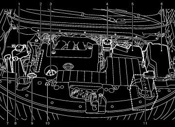
HOOD
GUID-630E41D7-1110-41BE-B348-7C70A778EED1
Black plate (165,1)
If you see steam or smoke coming from the engine compartment, to avoid injury do not open the hood.
SPA2858
been stopped. When closing the hood: 1. Reset the support rod to its original position. 2. Slowly move the hood down to latch the lock. Push the hood down to lock the hood securely into place.
and insert it
WARNING
When opening the hood: 1. Pull
the hood lock release handle *1
thelocated below the instrument panel; hood will then spring up slightly.
2. Locate the lever *2
in between the hood and grille and push the lever sideways with your fingertips.
3. Raise the hood *3 . 4. Remove the support rod *4
into the slot *5 .
Hold the coated part *A when removing or resetting the support rod. Avoid direct contact with the metal parts, as they may be hot immediately after the engine has
. Make sure the hood is completely closed and latched before driving. Failure to do so could cause the hood to fly open and result in an accident.
[ Edit: 2011/ 10/ 27 Model: E52-D ]
Pre-driving checks and adjustments 3-25
Black plate (166,1)
inserting the mechanical key into the driver’s door key cylinder and turning it to the rear of the vehicle twice.
The vehicle is stopped.
To close the lift gate, pull down until it securely locks. OPERATING POWER LIFT GATE (if so equipped) GUID-7F38D666-2E55-40AB-BCD1-B6181959F569
The power lift gate system can be operated when all of following conditions are satisfied. . Battery voltage is normal. The lift gate is unlocked. The selector lever is in the P (Park) position. If the conditions are interrupted when the power lift gate is being operated, the operation may stop. In this case, if the conditions above are met the power return to normal.lift gate operation will
LIFT GATE
GUID-3372BFB2-9331-43AE-B8D3-9873A4D9A889
WARNING
. Always be sure the lift gate has been closed securely to prevent it from opening while driving.
. Do not drive with the lift gate open. This could allow dangerous exhaust gases to be drawn into the vehicle. See “Exhaust gas (carbon monox- ide)” (P.5-2) of this manual.
. Do not leave children unattended inside the vehicle. They could un- knowingly activate switches or con- trols. Unattended children could become involved in serious acci- dents.
. Always be sure that hands and feet are clear of the gate frame to avoid injury while closing the lift gate.
SPA2881
OPERATING MANUAL LIFT GATE GUID-6547F12E-679C-4C90-A7BE-728052F910EE To open the lift gate, unlock it and push the lift gate opener switch *A . Pull up the lift gate to open. The lift gate can be unlocked by: pushing the unlock button Intelligent Key twice. pushing the lift gate request switch while carrying the Intelligent Key. pushing the door handle request switch twice while carrying the Intelligent Key. pushing the power door lock switch to the unlock position.
on the
3-26 Pre-driving checks and adjustments
[ Edit: 2011/ 10/ 27 Model: E52-D ]
Black plate (167,1)
SPA2547
SPA2860
SPA2851
Power lift gate switch — Instrument panel
Intelligent Key
Power door main switch GUID-F1B8F4A6-248F-4B7B-BB22-BACD6A2596FA The power lift gate operation can be turned on or off by the power door main switch on the instrument panel. When the power door main switch is pushed to the OFF position, the power operation is not available by the power lift gate switch on the lift gate and lift gate opener switch.
Lift gate opener switch
Power lift gate switch — Lift gate
SPA2859
SPA2852
Pre-driving checks and adjustments 3-27
[ Edit: 2011/ 10/ 27 Model: E52-D ]
Black plate (168,1)
NOTE:
If the pinch sensor is damaged or removed, the power close function will not operate.
WARNING
There is a small distance immediately before the closed position that cannot be detected. Make sure that all passen- gers keep their hands, etc., clear from the lift gate opening before closing the lift gate.
Manual mode GUID-FB81CA50-B914-43D8-8C60-3691116C5C60
If power operation is not available, the lift gate can be operated manually. Power operation may not be available if multiple obstacles have been detected in a single power cycle or if the battery voltage is low. When the power door main switch is in the OFF position, the lift gate can be opened manually by pushing the lift gate opener switch. If the power lift gate opener switch is pushed during power open or close, the power operation will be canceled and the lift gate can be operated manually.Reverse function GUID-F21D810B-0D64-4693-9BD3-ECC224DEB669
The power lift gate will reverse immediately if one of the following actions is performed during power open or power close.pushing the power lift gate switch *A on the instrument panel pushing the lift gate switch *D on the lower part of the lift gate pushing the lift gate button the Intelligent Key.
*C on
The outside chime sounds when the lift gate starts to reverse.
Auto reverse function GUID-EA666371-C5BC-46BB-87EE-855747261984
The auto-reverse function enables the lift gate to automatically reverse when something is caught in the lift gate as it is opening or closing. When the control unit detects an obstacle, the lift gate will reverse and return to the full open or full close position. If a second obstacle is detected, the lift gate motion will stop and the drive motor will disengage. The lift gate will enter the manual mode. A pinch sensor is mounted on each side of the lift gate. If an object is detected by the pinch sensor during power close, the lift gate will reverse and return to the full open position immediately.[ Edit: 2011/ 10/ 27 Model: E52-D ]
Power open GUID-E520941D-2FFA-475E-A192-DF411DDFD2D0
When the lift gate is fully closed, the lift gate will fully open automatically by:pushing the power lift gate switch *A on the instrument panel for more than 1 second pushing the lift gate opener switch *B pushing the power lift gate button *C on the Intelligent Key for more than 1 second
The hazard flashes 4 times and the outside chime sounds when the lift gate starts opening. NOTE:
The lift gate can be opened by the power lift gate switch *A or the lift gate button *C even if the lift gate is locked or the power door main switch is in the OFF position. The lift gate will unlock and open. Power close GUID-F581054C-64D4-4DCE-902F-9479C5B32588
When the lift gate is fully opened, the lift gate will fully close automatically by:pushing the power lift gate switch *A on the instrument panel for more than 1 second pushing the power lift gate switch *D on the lower part of the lift gate pushing the lift gate button *C Intelligent Key for more than 1 second
on the
The hazard flashes 4 times and the outside chime sounds when the lift gate starts closing.
3-28 Pre-driving checks and adjustments
Black plate (169,1)
CAUTION
CAUTION
The lift gate will automatically close from a partly open position. To avoid pinching, keep hands and fingers away from lift gate opening.
. Do not let children operate the lift
gate.
If the power lift gate does not stay open or if the lift gate unexpectedly closes at any time, do not operate the lift gate. There may be a pres- sure loss in one or both of the lift gate gas stays. Have the lift gate inspected by a NISSAN dealer.
. Do not activate the power lift gate if one or both of the lift gate gas stays are removed. Damage to the lift gate or power lift gate mechanisms may occur.
AUTO CLOSURE GUID-3B1D39A3-3EF9-45F3-A29F-CC3127C34A67
If the lift gate is pulled down to a partly open position, the lift gate will pull itself to the closed position. Do not apply excessive force when the auto closure is operating. Excessive force applied may cause the mechanism to malfunction.SPA2853
Safe Mode If the gas stays of the lift gate *1
GUID-BF0F4989-00E7-46EF-8DE8-14185CAF7708
lose pressure, the power lift gate safe mode is activated. When the safe mode is activated, the lift gate intermittently closes. Then the lift gate will be pulled to the closed and latched position by a motor. The power lift gate cannot be opened using the switches at any time in the safe mode. Do not operate the lift gate again until checked by a NISSAN dealer.it is
[ Edit: 2011/ 10/ 27 Model: E52-D ]
Pre-driving checks and adjustments 3-29
Black plate (170,1)
FUEL-FILLER DOOR
GUID-C38D74A3-B5E4-45F1-B8DD-D64040636D5B
FUEL-FILLER CAP
GUID-44612B06-98FA-409F-B78B-77A787FE5AFE
WARNING
. Gasoline is extremely flammable and highly explosive under certain conditions. You could be burned or seriously injured if it is misused or mishandled. Always stop engine and do not smoke or allow open flames or sparks near the vehicle when refueling.
. Do not attempt to top off the fuel tank after the fuel pump nozzle shuts off automatically. Continued refueling may cause fuel overflow, resulting in fuel spray and possibly a fire.
. Use only an original equipment type fuel-filler cap as a replacement. It has a built-in safety valve needed for proper operation of the fuel system and emission control sys- tem. An incorrect cap can result in a serious malfunction and possible injury. It could also cause the mal- function indicator light to come on.
SPA2824
SPA2861
GUID-E4CC93EC-80CA-424A-908E-2CCB6B10AC83
the lift gate cannot be opened due to aLIFT GATE RELEASE If discharged battery, follow these steps. 1. Remove the cover *1
inside of the lift gate
OPENING FUEL-FILLER DOOR GUID-E9391A06-17F2-4C74-A1CF-382481649761
To open the fuel-filler door, pull the fuel-filler door opener handle *1 .with a suitable tool.
2. Move the lever *2 as illustrated to open the
lift gate.
Have the vehicle checked by a NISSAN dealer.
3-30 Pre-driving checks and adjustments
[ Edit: 2011/ 10/ 27 Model: E52-D ]
Black plate (171,1)
JVP0067X
To remove the fuel-filler cap: 1. Turn the fuel-filler cap counterclockwise *1
to remove.
2. Hang the tether of the cap on the hook *3
while refueling.
To install the fuel-filler cap: 1.
Insert the fuel-filler cap straight into the fuel- filler tube.
2. Turn the fuel-filler cap clockwise *2 until a
single click is heard.
Pre-driving checks and adjustments 3-31
. Never pour fuel
into the throttle body to attempt to start your vehi- cle.
. Close the sliding door before open-
ing the fuel-filler door.
. Do not fill a portable fuel container in the vehicle or trailer. Static elec- tricity can cause an explosion of flammable liquid, vapor or gas in any vehicle or trailer. To reduce the risk of serious injury or death when filling portable fuel containers:
— Always place the container on
the ground when filling.
— Do not use electronic devices
when filling.
— Keep the pump nozzle in contact with the container while you are filling it.
— Use only approved portable fuel containers for flammable liquid.
CAUTION
If fuel is spilled on the vehicle body, flush it away with water to avoid
paint damage.
Insert the cap straight into the fuel- filler tube, then tighten until the fuel-filler cap clicks. Failure to tight- en the fuel-filler cap properly may cause the malfunction indicator light (MIL) to illuminate. If the light illuminates because the fuel- filler cap is loose or missing, tighten or install the cap and continue to drive the vehicle. The light should turn off after a few driving trips. If the light does not turn off after a few driving trips, have the vehicle inspected by a NISSAN deal- er.
information, see For additional “Malfunction Indicator Light (MIL)” (P.2-17).
The LOOSE FUEL CAP warning will appear if the fuel-filler cap is not properly tightened. It may take a few driving trips for the message to be displayed. Failure to tighten the fuel-filler cap properly after the LOOSE FUEL CAP warning appears may cause the Malfunction Indicator Light (MIL) to illuminate.
[ Edit: 2011/ 10/ 27 Model: E52-D ]
Black plate (172,1)
SPA2854
GUID-BD604F52-3900-4557-8124-CE7156DB8A68
TILT OR TELESCOPIC OPERATION While pulling the lock lever down *1 , adjust the steering wheel up, down, forward or rearward *2 until the desired position is achieved. Push the lock lever up *3
steering wheel in place.firmly to lock the
TILT/TELESCOPIC STEERING
GUID-069AD6A7-46A9-4905-AAAB-02A7C1D8C33D
WARNING
. Do not adjust the steering wheel while driving. You could lose control of your vehicle and cause an acci- dent.
. Do not adjust the steering wheel any closer to you than is necessary for proper steering operation and comfort. The driver’s air bag inflates with great force. If you are unrest- rained, leaning forward, sitting side- ways or out of position in any way, you are at greater risk of injury or death in a crash. You may also receive serious or fatal injuries from the air bag if you are up against it when it inflates. Always sit back against the seatback and as far away as practical from the steering wheel. Always use the seat belts.
[ Edit: 2011/ 10/ 27 Model: E52-D ]
SPA2833
LOOSE FUEL CAP warning GUID-D54C2F61-6C72-4B15-9740-B6A0DD544BCF The LOOSE FUEL CAP warning appears on the dot matrix liquid crystal display when the fuel- tightened correctly after the filler cap is not vehicle has been refueled. It may take a few driving trips for the message to be displayed. To turn off the warning, perform the following steps: 1. Remove and install the fuel-filler cap as soon as possible. (See “Fuel-filler cap” (P.3-30).)
2. Tighten the fuel-filler cap until it clicks. 3. Push the reset switch *A on the right side of the combination meter for about 1 second to turn off the LOOSE FUEL CAP warning after tightening the fuel cap.
3-32 Pre-driving checks and adjustments
Black plate (173,1)
SUN VISORS
MIRRORS
GUID-4CFDB9D2-58AF-4A8C-90ED-BCCDAEB2429B
GUID-64DBF7D1-4713-4227-96C7-5B25E941248E
CAUTION
. Do not store the main sun visor before storing the extension sun visor.
. Do not pull the extension sun visor
forcedly downward.
1. To block out glare from the front, swing
down the main sun visor *1 .
2. To block glare from the side, remove the main sun visor from the center mount and swing it to the side *2 .
3. Draw out the extension sun visor *3
from the main sun visor to block from further glare.
SPA2447
INSIDE MIRROR GUID-A519B782-D726-414C-B567-ECBC5D961F3E Adjust the height and the angle of the inside mirror to the desired position.
SIC3451
Pre-driving checks and adjustments 3-33
[ Edit: 2011/ 10/ 27 Model: E52-D ]
Black plate (174,1)
is designed so that
Automatic anti-glare type GUID-1BF23A99-F7FF-4C78-BE01-4E0480FD45F8
The inside mirror it automatically changes reflection according to the intensity of the headlights of the following vehicle. The anti-glare system will be automatically turned on when the ignition switch is pushed to the ON position. When the anti-glare system is turned on, the indicator light *A will illuminate and excessive glare from the headlights of the vehicle behind you will be reduced. switch *B to make the Type A: Push the inside rearview mirror operate normally and the indicator light will turn off. Push the switch again to turn the system on. Type B: Push the “*” switch *C to make the inside rearview mirror operate normally. The indicator light will turn off. Push the “I” switch *D to turn the system on. Do not allow any object to cover the sensors *E or apply glass cleaner on them. Doing so will reduce the sensitivity of the sensor, resulting in improper opera- tion. For the compass (if so equipped) operation, see “Compass” (P.2-8). For the HomeLink® Universal Transceiver opera-SPA2143
SPA2422A
GUID-1D65C108-5B16-4D9F-964E-FAEC8D474701
Manual anti-glare type The night position *1 will reduce glare from the headlights of vehicles behind you at night. Use the day position *2 when driving in daylight hours.
WARNING
Use the night position only when ne- cessary, because it reduces rear view clarity.
3-34 Pre-driving checks and adjustments
Type A
SPA2450
Type B
[ Edit: 2011/ 10/ 27 Model: E52-D ]
tion, see “HomeLink® Universal Transceiver” (P.2-59). OUTSIDE MIRRORS
GUID-453562C8-408F-49F2-AD9F-C932B1E3BE8B
WARNING
Objects viewed in the outside mirror on the passenger side are closer than they appear. Be careful when moving to the right. Using only this mirror could cause an accident. Use the inside mirror or glance over your shoulder to properly judge distances to other objects.
Black plate (175,1)
Defrosting outside mirrors (if so equipped) GUID-5C48E210-5008-4308-866B-AB2FFF2BB8A7
The outside mirrors will be heated when the rear window defroster switch is operated.Reverse tilt-down feature (if so equipped) GUID-A189001C-CDA4-4A60-B7F7-80745BCD7DA2
When backing up the vehicle, the right and left outside mirrors will turn downward automatically to provide better rear visibility. 1. Push the ignition switch to the ON position. 2. Move the selector lever to the R (Reverse)SPA2319
position.
Adjusting outside mirrors GUID-3DE81B55-145D-473A-8597-17FABDD1E16A The outside mirror control switch is located on the armrest. The outside mirror will operate only when the ignition switch is in the ACC or ON position. Turn the switch right or left to select the right or left side mirror *1 , then adjust using the control switch *2 .
3. Choose the right or left outside mirror by operating the outside mirror control switch. 4. The outside mirror surfaces move down-
ward.
When one of the following conditions has occurred, the outside mirror surfaces will return to their original positions.
The selector lever is moved to any position other than R (Reverse). The outside mirror control switch is set to the center position. The ignition switch is pushed to the OFF position.
[ Edit: 2011/ 10/ 27 Model: E52-D ]
Pre-driving checks and adjustments 3-35
Black plate (176,1)
SPA1829
SIC4448
SPA2830
Foldable outside mirrors GUID-C1C0EE4F-25B0-44D4-AE32-5F77B5E3E29F Fold the outside mirror by pushing it toward the rear of the vehicle.
VANITY MIRROR GUID-C84F4FB4-8EE7-48D6-B741-CC07C946F427
To use the front vanity mirror, pull down the sun visor and pull up the cover.COMMUNICATION MIRROR (if so equipped) GUID-B811515D-3E5A-4885-B966-B002ED367C00
The communication mirror can be used to view the second or third row seat inside the vehicle. To use the communication mirror, push the lid. To store the mirror, push it in until it latches.3-36 Pre-driving checks and adjustments
[ Edit: 2011/ 10/ 27 Model: E52-D ]
AUTOMATIC DRIVE POSITIONER (if so equipped)
GUID-D7276E5F-FB84-463B-BDF9-A346295A447B The automatic drive positioner system has two features: . Entry/exit function . Memory storage ENTRY/EXIT FUNCTION GUID-5F29AE45-A8DA-42BF-A7C8-04256D167074
This system is designed so that the driver’s seat will automatically move when the selector lever is in the P (Park) position. This allows the driver to get into and out of the driver’s seat more easily. The driver’s seat will slide backward when the driver’s door is opened with the ignition switch in the LOCK position. The driver’s seat will return to the previous positions when the ignition switch is pushed to the ACC position. The driver’s seat will not return to the previous positions if the seat adjusting switch is operated when the seat is at the exit position.Cancel or activate entry/exit function GUID-97B13C13-98B1-43DA-BF4E-6CC11E5EE734
The selector lever must be in the P (Park) position with the ignition switch in the OFF position. The entry/exit function can be activated or canceled by pressing and holding the SET switch for more than 10 seconds. The indicator lights on the memory switches (1and 2) will blink once when the function is canceled, and the indicator lights will blink twice when the function is activated. Note that the indicator lights may illuminate after 5 seconds while holding the SET switch. This indicates readiness for linking the Intelligent Key to a stored memory position. Keep the SET switch pressed for more than 10 seconds to turn on or off the entry/exit function. The entry/exit function can also be activated or canceled if the “Slide Driver Seat Back on Exit” key is turned to ON or OFF in the “Comfort” settings. (See “Vehicle information and settings (models with center multi-function control pa- nel)” (P.4-9).)
the entry/exit
Initialize entry/exit function GUID-E526DD89-2FEC-4DC6-8386-CED70B431AFF If the battery cable is disconnected, or if the fuse opens, function will not work though this function was set on before. In such a case, after connecting the battery or replacing with a new fuse, open and close the driver’s door more than two times after the ignition switch is placed in the LOCK position from the ON position. The entry/exit function will be activated.
[ Edit: 2011/ 10/ 27 Model: E52-D ]
Black plate (177,1)
SPA2855
MEMORY STORAGE GUID-BEDCA7A8-8409-4EC2-8EAE-7F30A20C2AA8
Two positions for the driver’s seat and outside mirrors can be stored in the automatic drive positioner memory. Follow this procedure to use the memory system. 1. Move the selector leverto the P (Park)
position.
2. Push the ignition switch to the ON position. 3. Adjust the driver’s seat and outside mirrors to the desired positions by manually operat- ing each adjusting switch. For additional information, see “Seats” (P.1-2) and “Out- side mirrors” (P.3-35).
Pre-driving checks and adjustments 3-37
Black plate (178,1)
. Within 45 seconds of opening the driver’s door, push the memory switch (1 or 2).
The driver’s seat and outside mirrors will move to the memorized position with the indicator light flashing, and then the light will stay on for approximately 5 seconds.
SYSTEM OPERATION GUID-B0CC6635-8934-4D55-BA9A-D54FF3D35461
The automatic drive positioner system will not work or will stop operating under the following conditions: . When the vehicle speed is above 4 MPH (7km/h) (entry/exit function).
. When the vehicle is driven (memory sto-
rage).
. When the adjusting switch for the driver’s seat is turned on while the automatic drive positioner is operating.
. When the driver’s seat and outside mirrors have already been moved to the memorized position.
. When no position is stored in the memory
switch.
. When the engine is started while moving the
automatic drive positioner.
. When the selector lever is moved from the P (Park) position to any other position. (How- ever, it will not be canceled while the driver’s
4. Push the SET switch and, within 5 seconds,
push the memory switch (1 or 2). The indicator light for the pushed memory switch will stay on for approximately 5
seconds after pushing the switch. If memory is stored in the same memory switch, the previous memory will be deleted.Linking Intelligent Key to a stored mem- ory position GUID-04712762-5C07-46C9-89DF-7F2803A498EB The Intelligent Key can be linked to a stored memory position with the following procedure. 1. Follow one of the steps for storing a memory
position.
. While the indicator light
for the memory switch being set is illuminated for 5 sec- onds, push the button on the Intelligent Key.
. Push the ignition switch to the OFF position,
and then push the SET switch. Push the button while pushing the memory button while the indicator light stays on for approxi- mately 5 seconds.
If the indicator light blinks, the Intelligent Key is linked to that memory setting. Push the ignition switch to the OFF position, and then push the button on the Intelligent Key. The driver’s seat and outside mirrors will move to the memorized position. 3-38 Pre-driving checks and adjustments
If
Confirming memory storage GUID-C7D22E67-E6D7-436F-A7E9-FBD8970F3E83
. Push the ignition switch to the ON position the main and push the SET switch. memory has not been stored, the indicator light will come on for approximately 0.5
second. When the memory has stored in position, the indicator light will stay on for approximately 5 seconds. If the battery cable is disconnected, or if the fuse opens, the memory will be canceled. In this case, reset the desired position using the previous procedure. If optional keys are added to your vehicle, the memory storage procedure to switch 1
or 2 and linking Intelligent Key procedure to a stored memory position should be per- formed again for each Intelligent Key. For additional Intelligent Key information, see “Keys” (P.3-3).Selecting the memorized position 1. Move the selector lever
GUID-66874194-881E-4A22-96FF-EE790B2F0E22
to the P (Park)position.
2. Use one of the following methods to move
the driver’s seat and outside mirrors. . Push the ignition switch to the ON position and push the memory switch (1
or 2).[ Edit: 2011/ 10/ 27 Model: E52-D ]
Black plate (179,1)
seat is returning to the previous positions (entry/exit function).)
. When the driver’s door remains open for more than 45 seconds and the ignition switch is not in the ON position.
[ Edit: 2011/ 10/ 27 Model: E52-D ]
Pre-driving checks and adjustments 3-39
Black plate (180,1)
MEMO
3-40 Pre-driving checks and adjustments
[ Edit: 2011/ 10/ 27 Model: E52-D ]
Black plate (181,1)
4 Monitor, heater, air conditioner, audio, phone
and voice recognition systems
Safety note ... Center multi-function control panel (if so equipped)
.................................................................................. 4-3
... ...... 4-4
.............................. 4-6How to use multi-function controller ... How to use touch screen (models with navigation system) Menu options (models with navigation system) How to select menus on the screen ...
.............................................................. 4-6
... .......... 4-8
.............................. 4-9...
Vehicle information and settings (models with center multi-function control panel)
... .................................................. 4-9
............................................. 4-9................................................................... 4-9
................................................ 4-10How to use STATUS button ... How to use brightness control and display ON/OFF button ... How to use DISP button ... How to use ECON button (models without navigation system) How to use INFO button ... How to use SETTING button ...
........................................................... 4-10
... ............................................... 4-10
....................................... 4-14
... .................................... 4-24
How to read the displayed lines ... .................................. 4-24
How to park with predicted course lines (if so equipped) Difference between predicted and actual distances ... Predictive course line settings (if so equipped) How to adjust the screen ... Operating tips ................................................................... 4-26
... ...... 4-29