- 2009 Nissan Altima Owners Manuals
- Nissan Altima Owners Manuals
- 2002 Nissan Altima Owners Manuals
- Nissan Altima Owners Manuals
- 1999 Nissan Altima Owners Manuals
- Nissan Altima Owners Manuals
- 2004 Nissan Altima Owners Manuals
- Nissan Altima Owners Manuals
- 2003 Nissan Altima Owners Manuals
- Nissan Altima Owners Manuals
- 1997 Nissan Altima Owners Manuals
- Nissan Altima Owners Manuals
- 2010 Nissan Altima Owners Manuals
- Nissan Altima Owners Manuals
- 1996 Nissan Altima Owners Manuals
- Nissan Altima Owners Manuals
- 2005 Nissan Altima Owners Manuals
- Nissan Altima Owners Manuals
- 1998 Nissan Altima Owners Manuals
- Nissan Altima Owners Manuals
- 2008 Nissan Altima Owners Manuals
- Nissan Altima Owners Manuals
- 2007 Nissan Altima Owners Manuals
- Nissan Altima Owners Manuals
- 2001 Nissan Altima Owners Manuals
- Nissan Altima Owners Manuals
- 2000 Nissan Altima Owners Manuals
- Nissan Altima Owners Manuals
- 2011 Nissan Altima Owners Manuals
- Nissan Altima Owners Manuals
- 2012 Nissan Altima Owners Manuals
- Nissan Altima Owners Manuals
- 2006 Nissan Altima Owners Manuals
- Nissan Altima Owners Manuals
- Download PDF Manual
-
WRS0380
4. Allow the seat belt to retract slightly. Pull up on the shoulder belt to remove any slack in the belt.
5. Before placing the child in the child restraint, use force to tilt the child restraint from side to side, and tug it forward to make sure that it is securely held in place. It should not move more than 1 inch.
6. Check that the retractor is in the automatic locking mode by trying to pull more seat belt out of the retractor. If you cannot pull any more belt webbing out of the retractor, the retractor is in the automatic locking mode.
Safety(cid:151)Seats, seat belts and supplemental air bags 1-41
Z REVIEW COPY:—2004 Altima (l30) Owners Manual (owners)—USA English (nna) 10/10/03—tbrooks X
2 Instruments and controls
Instrument panel. . . . . . . . . . . . . . . . . . . . . . . . . . . . . . . . . . . 2-2
Meters and gauges . . . . . . . . . . . . . . . . . . . . . . . . . . . . . . . . 2-3
Speedometer and odometer . . . . . . . . . . . . . . . . . . . . . 2-4
Trip computer (if so equipped) . . . . . . . . . . . . . . . . . . . 2-5
Tachometer . . . . . . . . . . . . . . . . . . . . . . . . . . . . . . . . . . . . 2-6
Engine coolant temperature gauge . . . . . . . . . . . . . . . 2-7
Fuel gauge . . . . . . . . . . . . . . . . . . . . . . . . . . . . . . . . . . . . 2-8
Warning/indicator lights and audible reminders . . . . . . . 2-9
Checking bulbs . . . . . . . . . . . . . . . . . . . . . . . . . . . . . . . . 2-9
Warning lights . . . . . . . . . . . . . . . . . . . . . . . . . . . . . . . . . 2-9
Indicator lights . . . . . . . . . . . . . . . . . . . . . . . . . . . . . . . . 2-11
Audible reminders . . . . . . . . . . . . . . . . . . . . . . . . . . . . . 2-13
Security systems . . . . . . . . . . . . . . . . . . . . . . . . . . . . . . . . . 2-13
Vehicle security system (if so equipped). . . . . . . . . . 2-13
Nissan vehicle immobilizer system (NVIS) . . . . . . . . 2-15
Windshield wiper and washer switch . . . . . . . . . . . . . . . 2-16
Switch operation . . . . . . . . . . . . . . . . . . . . . . . . . . . . . . 2-16Rear window and outside mirror (if so equipped) defroster switch . . . . . . . . . . . . . . . . . . . . . . . . . . . . . . . . . . 2-17
Headlight and turn signal switch. . . . . . . . . . . . . . . . . . . . 2-18
Xenon headlights (if so equipped) . . . . . . . . . . . . . . . 2-18
Headlight control switch. . . . . . . . . . . . . . . . . . . . . . . . 2-19
Daytime running light system (Canada only) . . . . . . 2-21Instrument brightness control . . . . . . . . . . . . . . . . . . . 2-21
Turn signal switch . . . . . . . . . . . . . . . . . . . . . . . . . . . . . 2-22
Fog light switch (if so equipped) . . . . . . . . . . . . . . . . 2-22
Hazard warning flasher switch . . . . . . . . . . . . . . . . . . . . . 2-23
Horn . . . . . . . . . . . . . . . . . . . . . . . . . . . . . . . . . . . . . . . . . . . .2-24
Heated seat (if so equipped). . . . . . . . . . . . . . . . . . . . . . . 2-24
Traction control system (TCS) off switch (if so equipped) . . . . . . . . . . . . . . . . . . . . . . . . . . . . . . . . . . 2-25
Power outlet . . . . . . . . . . . . . . . . . . . . . . . . . . . . . . . . . . . . . 2-26
Storage . . . . . . . . . . . . . . . . . . . . . . . . . . . . . . . . . . . . . . . . .2-27
Map pockets . . . . . . . . . . . . . . . . . . . . . . . . . . . . . . . . . . 2-27
Seatback pockets (if so equipped) . . . . . . . . . . . . . . 2-27
Sunglasses holder . . . . . . . . . . . . . . . . . . . . . . . . . . . . . 2-27
Cup holders . . . . . . . . . . . . . . . . . . . . . . . . . . . . . . . . . . 2-28
Glove box . . . . . . . . . . . . . . . . . . . . . . . . . . . . . . . . . . . . 2-29
Console box . . . . . . . . . . . . . . . . . . . . . . . . . . . . . . . . . . 2-29
Covered storage box. . . . . . . . . . . . . . . . . . . . . . . . . . . 2-31
Cargo net (if so equipped). . . . . . . . . . . . . . . . . . . . . . 2-32
Windows . . . . . . . . . . . . . . . . . . . . . . . . . . . . . . . . . . . . . . . .2-32
Power windows . . . . . . . . . . . . . . . . . . . . . . . . . . . . . . . 2-32
Sunroof (if so equipped). . . . . . . . . . . . . . . . . . . . . . . . . . . 2-34
Automatic sunroof . . . . . . . . . . . . . . . . . . . . . . . . . . . . . 2-34
Interior light . . . . . . . . . . . . . . . . . . . . . . . . . . . . . . . . . . . . . . 2-36Z REVIEW COPY:—2004 Altima (l30) Owners Manual (owners)—USA English (nna) 10/13/03—tbrooks X
Map lights . . . . . . . . . . . . . . . . . . . . . . . . . . . . . . . . . . . . . . . 2-37
Trunk light . . . . . . . . . . . . . . . . . . . . . . . . . . . . . . . . . . . . . . . 2-38
HomelinkT universal transceiver (if so equipped) . . . . . 2-38
Programming HomeLinkT. . . . . . . . . . . . . . . . . . . . . . . 2-39
Programming HomeLinkT for Canadian customers . . . . . . . . . . . . . . . . . . . . . . . . . . . . . . . . . . . . 2-40
Operating the HomeLinkT universal transceiver. . . . . . . . . . . . . . . . . . . . . . . . . . . . . . . . . . . . 2-40Programming trouble-diagnosis . . . . . . . . . . . . . . . . . 2-40
Clearing the programmed information . . . . . . . . . . . . 2-40
Rolling code programming. . . . . . . . . . . . . . . . . . . . . . 2-40
Reprogramming a single HomeLinkT button . . . . . . 2-41
If your vehicle is stolen . . . . . . . . . . . . . . . . . . . . . . . . . 2-41Z REVIEW COPY:—2004 Altima (l30) Owners Manual (owners)—USA English (nna) 10/13/03—tbrooks X
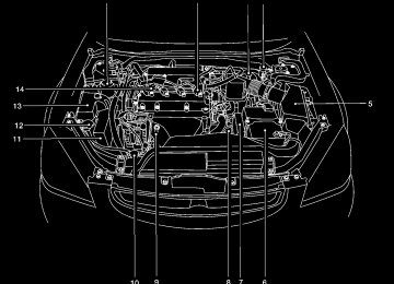
INSTRUMENT PANEL
2-2 Instruments and controls
1.
Headlight and turn signal switch (P. 2-18)
2. Meters and gauges (P. 2-3) 3. Windshield wiper/washer switch
4. 5.
6.
(P. 2-16) Center ventilator (P. 4-2) Audio system controls (if so equipped) (P. 4-14) Front passenger supplemental air bag (P. 1-8)
7. Glove box (P. 2-29) 8.
Heater and air conditioner (manual) (P. 4-3) Hazard warning flasher switch (P. 2-23)
9.
10. Power outlet (P. 2-26) 11. Rear window defroster switch (manual)
(P. 2-17)
12. Cruise control main/set switch (if so
equipped) (P. 5-12)
13. Driver supplemental air bag (P. 1-8) 14. Steering wheel switch for audio control
(if so equipped) (P. 4-29)
15. Tilt/telescopic steering wheel controls
(P. 3-14)
16. Traction control system (TCS) off switch (if so equipped) (P. 2-25)
WIC0605
Z REVIEW COPY:—2004 Altima (l30) Owners Manual (owners)—USA English (nna) 10/13/03—tbrooks X
METERS AND GAUGES
Instrument brightness control (P. 2-21) 17. 18. Outside mirror remote control (P. 3-17) 19. Front defroster switch (automatic)
(P. 4-10)
20. Heater and air conditioner (automatic)
(P. 4-10)
21. Rear window defroster switch (auto-
matic) (P. 2-17)
Tachometer
1. 2. Warning/indicator lights 3. 4.
Speedometer Automatic transmission position indica- tor lights (if so equipped) Engine coolant temperature gauge
5.
Fuel gauge
6. 7. Odometer/trip odometer
LIC0606
Instruments and controls 2-3
Z REVIEW COPY:—2004 Altima (l30) Owners Manual (owners)—USA English (nna) 10/13/03—tbrooks X
Odometer/Twin trip odometer (if so equipped) The odometer/twin trip odometer (if so equipped) is displayed when the ignition key is in the ON position. The odometer records the total distance the ve- hicle has been driven. The twin trip odometer (if so equipped) records the distance of individual trips.
WIC0600
Speedometer
1. 2. Odometer/twin trip display 3. Change button SPEEDOMETER AND ODOMETER Speedometer The speedometer indicates vehicle speed in miles per hour (MPH) and kilometers per hour (km/h).
2-4 Instruments and controls
WIC0601
! Trip
Changing the display: Pushing the change button changes the display as follows: ! Outside temperature Trip ! Distance to Empty ! Average economy ! Average speed ! Elapsed time ! Trip Resetting the trip odometer: Pushing the change button for more than 1 sec- ond resets the trip odometer to zero.
Z REVIEW COPY:—2004 Altima (l30) Owners Manual (owners)—USA English (nna) 10/10/03—tbrooks X
TRIP COMPUTER (if so equipped) The display of the trip computer is situated in the speedometer display. When the ignition is turned to ON, the display scrolls all the modes of the trip computer and then shows the mode chosen be- fore the ignition switch is turned OFF. If the battery terminal is disconnected, push the trip computer mode switch more than 1 second to activate the computer.
before the warning occurred. The ICY indicator will continue blinking as long as the temperature remains below 39(cid:176)F (4(cid:176)C).
The ambient temperature sensor is located in front of the radiator. The sensor may be affected by road or engine heat, wind directions and other driving conditions. The display may differ from the actual ambient temperature or the temperature displayed on various signs or billboards. Distance to empty (dte(cid:151)mile or km) The distance to empty (dte) mode provides you with an estimation of the distance that can be driven before refueling. The dte is constantly be- ing calculated, based on the amount of fuel in the fuel tank and the actual fuel consumption.
The display is updated every 30 seconds.
The dte mode includes a low range warning feature: when the fuel level is low, the dte mode is automatically selected and the digits blink in or- der to draw the driver(cid:146)s attention. Press the mode switch if you wish to return to the mode that was selected before the warning occurred. The dte mark (dte) will remain blinking until the vehicle is refueled.
When the fuel display will change to (----).
level drops even lower, the dte
Instruments and controls 2-5
WIC0267
When the ignition switch is turned to ON, modes of the trip computer can be selected by pushing the trip mode switch on the steering wheel switch for audio controls or by the trip computer change button. The following modes can be selected: Outside air temperature (ICY-(cid:176)F or (cid:176)C) The outside air temperature is displayed in (cid:176)F or (cid:176)C. The outside air temperature mode includes a low temperature warning feature: below 37(cid:176)F (3(cid:176)C), the outside air temperature mode is automatically selected and ICY will illuminate in order to draw the driver(cid:146)s attention. Press the mode switch if you wish to return to the mode that was selectedZ REVIEW COPY:—2004 Altima (l30) Owners Manual (owners)—USA English (nna) 10/10/03—tbrooks X
Journey time The journey time mode shows the time since the last reset. The displayed time can be reset by pressing the mode switch for more than approxi- mately 1 second.
NOTE: If a low temperature warning and low range warning occur simultaneously, other dis- play modes switch automatically to the outside temperature display. When the mode switch is pushed, the dis- play switches to the mode chosen before the warning display, and the outside air temperature indicator marked ICY will blink.
NOTE: c If the amount of fuel added while the ignition switch is OFF is small, the dis- play just before the ignition switch is turned OFF may continue to be dis- played.
c When driving uphill or rounding curves, the fuel in the tank shifts, which may momentarily change the display. Average fuel consumption (mpg or l/100km) The average fuel consumption mode shows the average fuel consumption since the last reset. Resetting is done by pressing the mode switch for more than approximately 1 second. The dis- play is updated every 30 seconds. At about the first 1/3 miles (500 m) after a reset, the display shows (----). Average speed (mph or km/h) The average speed mode shows the average vehicle speed since last reset. Resetting is done by pressing the mode switch for more than ap- proximately 1 second. The display is updated every 30 seconds. The first 30 seconds after a reset, the display shows (----).
2-6 Instruments and controls
Type A
WIC0268
TACHOMETER The tachometer indicates engine speed in revo- lutions per minute (r/min). Do not rev engine into the red zone s1 .
CAUTION
When engine speed approaches the red zone, shift to a higher gear. Operating the engine in the red zone may cause serious engine damage.
Z REVIEW COPY:—2004 Altima (l30) Owners Manual (owners)—USA English (nna) 10/10/03—tbrooks X
CAUTION
If the gauge indicates engine coolant tem- perature over the normal range, stop the vehicle as soon as safely possible. If the engine is overheated, continued opera- tion of the vehicle may seriously damage the engine. See (cid:147)If your vehicle over- heats(cid:148) in the (cid:147)In case of emergency(cid:148) sec- tion for immediate action required.
WIC0269
Type B
WIC0607
ENGINE COOLANT TEMPERATURE GAUGE The gauge indicates the engine coolant tempera- ture. The engine coolant temperature is within the normal range s1 when the gauge needle points within the zone shown in the illustration.The engine coolant temperature varies with the outside air temperature and driving conditions.
Instruments and controls 2-7
Z REVIEW COPY:—2004 Altima (l30) Owners Manual (owners)—USA English (nna) 10/10/03—tbrooks X
The located on the driver(cid:146)s side of the vehicle.
indicates that the fuel filler lid is
CAUTION
c If
the vehicle runs out of
fuel, malfunction indicator lamp the (MIL) may come on. Refuel as soon as possible. After a few driving trips, the lamp should turn off. If the lamp remains on after a few driving trips, have the vehicle inspected by a NISSAN dealer.
c For additional information, see (cid:147)Mal- function indicator lamp (MIL)(cid:148) later in this section.
WIC0608
FUEL GAUGE The gauge indicates the approximate fuel level in the tank.
The gauge may move slightly during braking, turning, acceleration, or going up or down hills.
The gauge needle returns to E (Empty) after the ignition key is turned to OFF.
The low fuel warning light comes on when the amount of fuel in the tank is getting low. Refill the fuel tank before the gauge regis- ters E (Empty).
2-8 Instruments and controls
Z REVIEW COPY:—2004 Altima (l30) Owners Manual (owners)—USA English (nna) 10/10/03—tbrooks X
WARNING/INDICATOR LIGHTS AND AUDIBLE REMINDERS
or
or
Anti-lock brake warning light (if so equipped)
Low windshield washer fluid warning light
Brake warning light
Seat belt warning light and chime
Cruise SET switch indicator light (if so equipped)
High beam indicator light (Blue)
Charge warning light
Supplemental air bag warning light
Malfunction indicator lamp (MIL)
Door open warning light
Trunk lid open warning light
Slip indicator light (if so equipped)
Engine oil pressure warning light
Low fuel warning light
Automatic transmission position indicator light (A/T models)
Traction control system off indicator light (if so equipped)
CRUISE main switch indicator light (if so equipped)
Turn signal/hazard indicator lights
CHECKING BULBS With all doors closed, apply the parking brake and turn the ignition key to the ON position without starting the engine. The following lights will come on:
If any light fails to come on, it may indicate a burned-out bulb or an open circuit in the electrical system. Have the system repaired promptly. WARNING LIGHTS
or
or
The following lights come on briefly and then go off:
or
Anti-lock brake warning light (if so equipped)
If the light comes on while the engine is running, it may indicate the anti-lock brake system is not functioning properly. Have the system checked by a NISSAN dealer.
Turn off the engine, and start it again by slowly turning the ignition key (quickly do- ing so may cause the ABS light to stay on when there is nothing wrong). If the light stays on, have the system checked by a NISSAN dealer.
If an abnormality occurs in the system, the anti- lock function ceases, but the regular braking system continues to operate. If the light comes on while you are driving, contact a NISSAN dealer for repair.
Instruments and controls 2-9
Z REVIEW COPY:—2004 Altima (l30) Owners Manual (owners)—USA English (nna) 10/10/03—tbrooks X
or
Brake warning light
This light functions for both the parking brake and the foot brake systems.
When the ignition key is in the ON position, the light comes on when the parking brake is applied, and also warns of a low brake fluid level. If the light comes on while the engine is running with the parking brake not applied, stop the vehicle and perform the following:
1. Check the brake fluid level. Add brake fluid as necessary. See (cid:147)Brake and clutch fluid(cid:148) in the (cid:147)Maintenance and do-it-yourself(cid:148) sec- tion of this manual.
2.
If the brake fluid level is correct, have the brake system checked by a NISSAN dealer.
WARNING
c Your brake system may not be working properly if the warning light is on. Driv- ing could be dangerous. If you judge it to be safe, drive carefully to the nearest service station for repairs. Otherwise, have your vehicle towed because driv- ing it could be dangerous.
2-10 Instruments and controls
c Pressing the brake pedal with the en- gine stopped and/or a low brake fluid level may increase your stopping dis- tance and braking will require greater pedal effort as well as pedal travel.
c If the brake fluid level
is below the MINIMUM or MIN mark on the brake fluid reservoir, do not drive until the brake system has been checked at a NISSAN dealer.
Charge warning light
If this light comes on while the engine is running, it may indicate the charging system is not func- tioning properly. Turn the engine off and check the generator belt. If the belt is loose, broken, missing, or if the light remains on, see a NISSAN dealer immediately.
CAUTION
Do not continue driving if the generator belt is loose, broken or missing.
Door open warning light
This light comes on when any of the doors are not closed securely while the ignition key is in the ON position.
Engine oil pressure warning light
This light warns of low engine oil pressure. If the light flickers or comes on during normal driving, pull off the road in a safe area, stop the engine immediately and call a NISSAN dealer or other authorized repair shop. The engine oil pressure warning light is not designed to indicate a low oil level. Use the dipstick to check the oil level. See (cid:147)Engine oil(cid:148) in the (cid:147)Maintenance and do-it-yourself(cid:148) section of this manual.
CAUTION
Running the engine with the engine oil pressure warning light on could cause se- rious damage to the engine almost imme- diately. Such damage is not covered by warranty. Turn off the engine as soon as it is safe to do so.
Low fuel warning light
This light comes on when the fuel level in the fuel tank is getting low. Refuel as soon as it is conve- nient, preferably before the fuel gauge reaches E (Empty). There will be a small reserve of fuel in the tank when the fuel gauge needle reaches E (Empty).
Z REVIEW COPY:—2004 Altima (l30) Owners Manual (owners)—USA English (nna) 10/10/03—tbrooks X
Low windshield washer fluid warning light
This light comes on when the windshield washer fluid is at a low level. Add windshield washer fluid as necessary. See the (cid:147)Maintenance and do-it- yourself(cid:148) section of this manual.
Seat belt warning light and chime
The light and chime remind you to fasten your seat belts. The light illuminates whenever the ignition key is turned to the ON or START position and remains illuminated until the driver(cid:146)s seat belt is fastened. At the same time, the chime sounds for about 7 seconds unless the driver(cid:146)s seat belt is securely fastened. Refer to (cid:147)Seat belts(cid:148) in the (cid:147)Safety(cid:151)Seats, seat belts and supplemental air bags(cid:148) section for pre- cautions on seat belt usage.
Supplemental air bag warning light
When the ignition key is in the ON or START position, the supplemental air bag warning light illuminates for about 7 seconds and then turns off. This means the system is operational. If any of the supplemental front air bag, supplemental side air
the following conditions occur,
bag (if so equipped), curtain side-impact air bags (if so equipped), and pre-tensioner seat belt sys- tems need servicing and your vehicle must be taken to a NISSAN dealer: c The supplemental air bag warning light re-
mains on after approximately 7 seconds.
c The supplemental air bag warning light
flashes intermittently.
c The supplemental air bag warning light does
not come on at all.
Unless checked and repaired, the supplemental restraint system (air bag system) and/or the pre- tensioner seat belts may not function properly. For additional details see (cid:147)Supplemental restraint system(cid:148) in the (cid:147)Seats, restraints and supplemen- tal air bag systems(cid:148) section of this manual.
WARNING
If the supplemental air bag warning light is on, it could mean that the supplemental front air bag, supplemental side air bag, curtain side-impact air bag systems (if so equipped) and/or pre-tensioner seat belt systems will not operate in an accident.
Trunk lid open warning light
This light comes on when the trunk lid is not securely closed while the ignition key is in the ON position. INDICATOR LIGHTS
Automatic transmission posi- tion indicator light (A/T mod- els)
When the ignition key is turned to the ON posi- tion, this indicator light shows the automatic transmission selector lever position. See (cid:147)Driving the vehicle(cid:148) in the (cid:147)Starting and driving(cid:148) section of this manual.
Cruise main switch indicator light (if so equipped)
The light comes on when the cruise control main switch is pushed. The light goes out when the main switch is pushed again. When the cruise main switch indicator light comes on, the cruise control system is operational.
Cruise set switch indicator light (if so equipped)
The light comes on while the vehicle speed is controlled by the cruise control system. If the light blinks while the engine is running, it may indicate Instruments and controls 2-11
Z REVIEW COPY:—2004 Altima (l30) Owners Manual (owners)—USA English (nna) 10/10/03—tbrooks X
the cruise control system is not functioning prop- erly. Have the system checked by a NISSAN dealer.
High beam indicator light (Blue)
This blue light comes on when the headlight high beams are on and goes out when the low beams are selected.
The high beam indicator light also comes on when the passing signal is activated.
Malfunction indicator lamp (MIL)
If this indicator lamp comes on steady or blinks while the engine is running, it may indicate a potential emission control malfunction.
The malfunction indicator lamp may also come on steady if the fuel filler cap is loose or missing, or if the vehicle runs out of fuel. Check to make sure the fuel filler cap is installed and closed tightly, and that the vehicle has at least 3 gallons of fuel in the fuel tank.
After a few driving trips, the lamp should turn off if no other potential emission control system malfunction exists.
2-12 Instruments and controls
Operation
The malfunction indicator lamp will come on in one of two ways: c Malfunction indicator lamp on steady (cid:151) An emission control system malfunction has been detected. Check the fuel filler cap. If the fuel filler cap is loose or missing, tighten or install the cap and continue to drive the lamp should turn off after vehicle. The a few driving trips. If the lamp does not turn off after a few driving trips, have the vehicle inspected by a NISSAN dealer. You do not need to have your vehicle towed to the dealer.
c Malfunction indicator lamp blinking (cid:151) An engine misfire has been detected which may damage the emission control system. To re- duce or avoid emission control system dam- age: (cid:150) do not drive at speeds above 45 MPH
(72 km/h).
(cid:150) avoid hard acceleration or deceleration. (cid:150) avoid steep uphill grades. (cid:150) if possible, reduce the amount of cargo
being hauled or towed.
The malfunction indicator lamp may stop blinking and come on steady. Have the vehicle inspected by
a NISSAN dealer. You do not need to have your vehicle towed to the dealer.
CAUTION
Continued vehicle operation without hav- ing the emission control system checked and repaired as necessary could lead to poor driveability, reduced fuel economy, and possible damage to the emission con- trol system.
Slip indicator light (if so equipped)
This indicator light will blink when the traction control system is limiting wheel spin. Slippery road conditions may exist if the slip indicator blinks on. If this happens, adjust your driving accordingly.
The slip indicator light also comes on when you turn the ignition key to the ON position. The light will turn off after about 2 seconds if the system is operational. If the light does not come on or go off, have the traction control system checked by a NISSAN dealer.
The system operates in all transmission shift lever positions, but the system can upshift the trans- mission only as high as the indicated shift lever position.
Z REVIEW COPY:—2004 Altima (l30) Owners Manual (owners)—USA English (nna) 10/10/03—tbrooks X
AUDIBLE REMINDERS Brake pad wear warning The disc brake pads have audible wear warnings. When a brake pad requires replacement, it makes a high pitched scraping sound when the vehicle is in motion, whether or not the brake pedal is depressed. Have the brakes checked as soon as possible if the warning sound is heard. Key reminder chime A chime sounds if the driver(cid:146)s door is opened while the key is left in the ignition switch. Remove the key and take it with you when leaving the vehicle. Light reminder chime With the ignition switch in the OFF position, a chime sounds when the driver(cid:146)s door is opened if the headlights or parking lights are on. Turn the headlight control switch off before leav- ing the vehicle.
Traction control system off indicator light (if so equipped) This indicator light comes on when the traction control off switch is pushed to OFF. This indi- cates the traction control system is not operating.
Push the traction control off switch again or re- start the engine and the system will operate nor- mally. See (cid:147)Traction control system (TCS)(cid:148) in the (cid:147)Starting and driving(cid:148) section of this manual.
The traction control light also comes on when you turn the ignition key to the ON position. The light will turn off after about 2 seconds if the traction control system (TCS) is operational. If the light stays on or comes on along with the SLIP indica- tor light while you are driving, have the traction control system checked by a NISSAN dealer.
While the traction control system is operating, you might feel slight vibration or hear the system working when starting the vehicle or accelerat- ing, but this is normal.
Turn signal/hazard indicator lights
The appropriate light flashes when the turn signal switch is activated. Both lights flash when the hazard switch is turned on.
SECURITY SYSTEMS
LIC0301
Your vehicle has two types of security systems: c Vehicle security system (if so equipped) c NISSAN Vehicle Immobilizer System(cid:151)NVIS VEHICLE SECURITY SYSTEM (if so equipped) The vehicle security system provides visual and audio alarm signals if parts of the vehicle are disturbed. How to arm the vehicle security sys- tem 1. Close all windows. (The system can be armed even if the windows are open.) Instruments and controls 2-13Z REVIEW COPY:—2004 Altima (l30) Owners Manual (owners)—USA English (nna) 10/10/03—tbrooks X
2. Remove the key from the ignition switch.
3. Close the trunk lid and all doors. Lock all doors. The doors can be locked with the key, power door is opened, locked, and then closed) or with the keyfob.
lock switch (if
the door
Keyfob operation: c Push the
button on the keyfob. All doors lock. The hazard lights flash twice and the horn beeps once to indicate all doors are locked.
c When the
button is pushed with all doors locked, the hazard lights flash twice and the horn beeps once as a re- minder that the doors are already locked.
The horn may or may not beep. Refer to (cid:147)Silencing the horn beep feature(cid:148) later in this section.
2-14 Instruments and controls
4. Confirm that the SECURITY indicator light comes on. The SECURITY light stays on for about 30 seconds. The vehicle security sys- tem is now pre-armed. After about 30 sec- onds the vehicle security system automati- cally shifts into the armed phase. The SECURITY light begins to flash once every 3
seconds. If, during the 30-second pre-arm time period, the door is unlocked by the key or the keyfob, or the ignition key is turned to ACC or ON, the system will not arm.c If the key is turned slowly when locking the door, the system may not arm. Fur- thermore, if the key is turned beyond the vertical position toward the unlock position to remove the key, the system may be disarmed when the key is re- moved. If the indicator light fails to glow for 30 seconds, unlock the door once and lock it again.
c Even when the driver and/or passen- gers are in the vehicle, the system will arm with all doors and trunk lid closed and locked with the ignition key in the OFF position.
Vehicle security system activation The vehicle security system will give the following alarm: c The headlights blink and the horn sounds
intermittently.
c The alarm automatically turns off after ap- proximately 45 seconds. However, the alarm reactivates if the vehicle is tampered with again. The alarm can be shut off by unlocking a door or trunk lid with the key, or by pressing the
button on the keyfob.
The alarm is activated by: c opening the door or trunk lid without using the key or keyfob (even if the door is un- locked by releasing the door inside lock switch).
How to stop an activated alarm The alarm stops only by unlocking a door or the trunk lid with the key, or by pressing the button on the keyfob.
Z REVIEW COPY:—2004 Altima (l30) Owners Manual (owners)—USA English (nna) 10/10/03—tbrooks X
WIC0271
Silencing the horn beep feature If desired, the horn beep feature can be deacti- vated using the keyfob. To deactivate: Press and hold both the and 2 seconds.
buttons at the same time for at least
The hazard lights will quickly flash 3 times to confirm that the horn beep feature has been deactivated. To activate: Press and hold both the and 2 seconds once more.
buttons at the same time for at least
The hazard lights will quickly flash once and the horn will sound once to confirm that the horn beep feature has been reactivated.
Deactivating the horn feature does not silence the horn if the alarm is triggered. If the system does not operate as described above, have it checked by a NISSAN dealer. NISSAN VEHICLE IMMOBILIZER SYSTEM (NVIS) The NISSAN Vehicle Immobilizer System (NVIS) will not allow the engine to start without the use of a registered NVIS key. If the engine fails to start using a registered NVIS key (for example, when interference is caused by another NVIS key, an automated toll road device or automatic payment device on the key ring), restart the engine using the following proce- dures: 1. Leave the ignition switch in the ON position
for approximately 5 seconds.
2. Turn the ignition switch to the OFF or LOCK position, and wait approximately 5 seconds.
3. Repeat steps 1 and 2. 4. Restart the engine while holding the device (which may have caused the interference) separate from the registered NVIS key.
If the no start condition re-occurs, NISSAN rec- ommends placing the registered NVIS key on a separate key ring to avoid interference from other devices. Statement related to Section 15 of FCC Rules for NISSAN Vehicle Immobilizer Sys- tem (CONT ASSY (cid:151) IMMOBILIZER, ANT ASSY (cid:151) IMMOBILIZER) This device complies with part 15 of the FCC Rules and RSS-210 of Industry Canada. Operation is subject to the follow- ing two conditions; (1) This device may not cause harmful in- terference, and (2) this device must accept any interference received, including inter- ference that may cause undesired opera- tion of the device. CHANGES OR MODIFICATIONS NOT EX- PRESSLY APPROVED BY THE MANUFAC- TURER FOR COMPLIANCE COULD VOID THE USER(cid:146)S AUTHORITY TO OPERATE THE EQUIPMENT.
Instruments and controls 2-15
Z REVIEW COPY:—2004 Altima (l30) Owners Manual (owners)—USA English (nna) 10/10/03—tbrooks X
WINDSHIELD WIPER AND WASHER SWITCH
If the light still remains on and/or the en- gine will not start, see a NISSAN dealer for NVIS service as soon as possible. Please bring all NVIS keys that you have when visiting your NISSAN dealer for service.
WIC0270
Security indicator light (NISSAN Ve- hicle Immobilizer System) The security indicator light s1 is located on the instrument panel near the windshield. The security indicator light blinks every 3 sec- onds whenever the ignition switch is in the LOCK, OFF or ACC position. This function indi- cates the NISSAN Vehicle Immobilizer System (NVIS) is operational. If the NVIS is malfunctioning, the light will remain on while the ignition key is in the ON position.
2-16 Instruments and controls
WIC0613
SWITCH OPERATION The windshield wiper and washer switch oper- ates when the ignition key is in the ON position.
Push the lever down to operate the wiper at the following speed: s1
Intermittent (cid:151) intermittent operation can be adjusted by turning the knob toward sA (Slower) or sB (Faster). s2
Low (cid:151) continuous low speed operation s3 High (cid:151) continuous high speed operation Push the lever up s4 to have one sweep opera- tion of the wiper.Z REVIEW COPY:—2004 Altima (l30) Owners Manual (owners)—USA English (nna) 10/10/03—tbrooks X
Pull the lever toward you s5
to operate the washer. The wiper will also operate several times.WARNING
In freezing temperatures the washer solu- tion may freeze on the windshield and obscure your vision which may lead to an accident. Warm the windshield with the defroster before you wash the windshield.
CAUTION
c Do not operate the washer continu-
ously for more than 30 seconds.
c Do not operate the washer if the reser-
voir tank is empty.
c Do not fill the window washer reservoir tank with washer fluid concentrates at full strength. Some methyl alcohol based washer fluid concentrates may perma- nently stain the grille if spilled while fill- ing the window washer reservoir tank.
c Pre-mix washer fluid concentrates with water to the manufacturer(cid:146)s recom- mended levels before pouring the fluid into the window washer reservoir tank. Do not use the window washer reservoir tank to mix the washer fluid concen- trate and water.
REAR WINDOW AND OUTSIDE MIRROR (if so equipped) DEFROSTER SWITCH
WIC0272
LIC0317
Type A
To defrost the rear window glass and outside mirrors (if so equipped), start the engine and push the rear window defroster switch on. The rear window defroster light on the switch comes on. Push the switch again to turn the defroster off. The rear window defroster automatically turns off after approximately 15 minutes.
indicator
Type B
CAUTION
When cleaning the inner side of the rear window, be careful not to scratch or dam- age the rear window defroster.
NOTE: The top few rows of wires on the rear win- dow are not part of the rear window de- froster system. These wires make up the antenna for the audio system.
Instruments and controls 2-17
Z REVIEW COPY:—2004 Altima (l30) Owners Manual (owners)—USA English (nna) 10/10/03—tbrooks X
(for example, when the vehicle stops at a traffic signal). Even when the daytime running lights are active (Canada only), the xenon headlights do not turn on. This way the life of the xenon head- lights is not reduced.
c If the xenon headlight bulb is close to burning out, the brightness will drasti- cally decrease, the light will start blink- ing, or the color of the light will be- come reddish. If one or more of the above signs appear, contact a NISSAN dealer.
HEADLIGHT AND TURN SIGNAL SWITCH
XENON HEADLIGHTS (if so equipped)
WARNING
cHIGH VOLTAGE
c When xenon headlights are on, they produce a high voltage. To prevent an electric shock, never attempt to modify or disassemble. Always have your xe- non headlights replaced at a NISSAN dealer.
c Xenon headlights provide considerably more light than conventional head- lights. If they are not correctly aimed, they might temporarily blind an oncom- ing driver or the driver ahead of you and cause a serious accident. If headlights are not aimed correctly, immediately take your vehicle to a NISSAN dealer and have the headlights adjusted correctly.
When the xenon headlight is initially turned on, its brightness or color varies slightly. However, the color and brightness will soon stabilize. c The life of xenon headlights will be shortened by frequent on-off opera- tion. It is generally desirable not to turn off the headlights for short intervals
Type C
LIC0637
2-18 Instruments and controls
Z REVIEW COPY:—2004 Altima (l30) Owners Manual (owners)—USA English (nna) 10/10/03—tbrooks X
Type A
Type B
Type C
WIC0312
WIC0313
WIC0314
HEADLIGHT CONTROL SWITCH Lighting s1 When turning the switch to the
posi- tion, the front parking, tail, license plate and instrument panel lights come on. s2 When turning the switch to the
posi- tion, the headlights come on and all the other lights remain on.
Instruments and controls 2-19
Z REVIEW COPY:—2004 Altima (l30) Owners Manual (owners)—USA English (nna) 10/10/03—tbrooks X
WIC0597
Autolight system (if so equipped) The autolight system allows the headlights to be set so they turn on and off automatically. The autolight system can: c Turn on the headlights automatically when it
is dark. See your NISSAN dealer to have the autolight activation sensitivity setting adjusted.
c Turn off the headlights when it is light. c Keep the headlights on for up to 180 sec- onds after you turn the key to OFF, open and
2-20 Instruments and controls
close the driver(cid:146)s or passenger(cid:146)s door, and then close all doors. The default time delay for autolight shutoff is 45 seconds. See your NISSAN dealer to have the time delay setting adjusted.
If the ignition switch is turned OFF and one of the doors is opened, the headlights remain ON for 5
minutes. To set the autolight system: 1. Make sure the headlight switch is in theAUTO position s1 .
2. Turn the ignition key to ON. 3. The autolight system automatically turns the
headlights on and off.
, or
position.
To turn the autolight system off, turn the switch to the OFF, Be sure you do not put anything on top of the autolight sensor located in the top driver side of the instrument panel. The autolight sensor controls the autolight; if it is covered, the autolight sensor reacts as if it is dark out and the headlights will illumi- nate. If this occurs while parked with the engine off and the key in the ON position, your vehicle(cid:146)s battery could become dis- charged.
LIC0318
Headlight beam select s1 To select the high beam function, push the lever forward. The high beam lights come on and the
light illuminates.
s2 Pull the lever back to select the low beam. s3 Pulling and releasing the lever flashes the
headlight high beams on and off.
Battery saver system If the ignition switch is turned OFF while the headlight switch is in the posi- tion, the headlights will turn off after 5 minutes.
or
Z REVIEW COPY:—2004 Altima (l30) Owners Manual (owners)—USA English (nna) 10/10/03—tbrooks X
CAUTION
WARNING
c Be sure to turn the light switch to the OFF position when you leave the ve- hicle for extended periods of time, oth- erwise the battery will go dead.
c Never leave the light switch on when the engine is not running for extended periods of time even if the headlights turn off automatically.
DAYTIME RUNNING LIGHT SYSTEM (Canada only) The headlights automatically illuminate at a re- duced intensity when the engine is started with the parking brake released. The daytime running lights operate with the headlight switch in the OFF position or in the position. Turn the headlight switch to the position for full illumination when driving at night.
If the parking brake is applied before the engine is started, the daytime running lights do not illumi- nate. The daytime running lights illuminate when the parking brake is released. The daytime run- ning lights will remain on until the ignition switch is turned off.
When the daytime running light system is active, tail lights on your vehicle are not on. It is necessary at dusk to turn on your headlights. Failure to do so could cause an accident injuring yourself and others.
WIC0273
INSTRUMENT BRIGHTNESS CONTROL The instrument cluster illuminates when the igni- tion switch is in ON position. The instrument brightness control operates when the the AUTO, Turn the control to adjust the brightness of instru- ment panel lights when driving at night. The instrument brightness control will not adjust the brightness when the headlights or parking lights are off.
headlight or
position.
control
switch
in
is
Instruments and controls 2-21
Z REVIEW COPY:—2004 Altima (l30) Owners Manual (owners)—USA English (nna) 10/10/03—tbrooks X
were left ON. The fog lights will be turned OFF by the Battery Saver function approxi- mately 5 minutes after is closed.
the last door
c If the ignition switch is turned to the ON position after the fog lights were turned OFF by the Battery Saver function, the fog lights will immediately come back ON.
Headlight switch in the AUTO position; nighttime operation c Fog lights, marker and taillights come ON. c Headlights come ON.
The lights can be adjusted to turn ON in brighter or dimmer environments. See your NISSAN dealer to have the sensi- tivity setting adjusted.
c Dash readouts dim unless the dimmer
switch is on full bright.
c If the ignition switch is in the OFF position with the fog lights turned ON, the fog lights will be turned OFF by the Twilight Sentinel function approximately 45 seconds after the last door is closed. The default setting is 45 seconds. See your NISSAN dealer to have this time adjusted up to 180 seconds.
LIC0319
TURN SIGNAL SWITCH Turn signal s1 Move the lever up or down to signal the turning direction. When the turn is com- pleted, the turn signals cancel automatically.
Lane change signal s2 To signal a lane change, move the lever up or down to the point where the indicator light begins to flash, but the lever does not latch.
2-22 Instruments and controls
WIC0320
FOG LIGHT SWITCH (if so equipped) Normal operation of the fog lights in the ON position: Headlight switch in the AUTO position; day- time operation c Fog lights, marker and taillights come ON. c Headlights do not come ON. c Dash readouts dim unless the dimmerswitch is on full bright.
c If the ignition switch is in the OFF position with the fog lights turned ON, a warning chime will sound indicating the fog lights
Z REVIEW COPY:—2004 Altima (l30) Owners Manual (owners)—USA English (nna) 10/10/03—tbrooks X
c If any door is opened when the ignition switch is in the OFF position, the Twilight Sentinel function operates for approximately 5 minutes. After approximately 5 minutes, the lights will turn OFF due to the Battery Saver function.
c If the ignition switch is turned to the ON position after the fog lights were turned OFF by the Twilight Sentinel function, the fog lights and the headlights will come ON to- gether when the Auto Light Sensor deter- mines it is dark enough. The fog lights will now operate independently of the headlights only if the headlight switch is turned OFF.
c When the high beams are turned ON, the fog lights will turn OFF. The fog lights will come back ON when the high beams are turned OFF.
Headlights turned ON and OFF by the driver (no AUTO headlight function); day or nighttime operation c Same operation as (cid:147)Headlight switch in the AUTO position; daytime operation(cid:148) de- scribed above.
Some of the Battery Saver and Twilight Sentinel functions can be turned ON and OFF or adjusted. Please see your NISSAN dealer if you have any questions.
HAZARD WARNING FLASHER SWITCH
To turn the fog lights OFF, turn the switch to the OFF position. The fog lights automatically turn off whenever the high beam headlight function is selected.
WIC0275
Push the switch on to warn other drivers when you must stop or park under emergency condi- tions. All turn signal lights flash.
WARNING
c If stopping for an emergency, be sure to
move the vehicle well off the road.
c Do not use the hazard warning flashers while moving on the highway unless unusual circumstances force you to drive so slowly that your vehicle might become a hazard to other traffic.
Instruments and controls 2-23
Z REVIEW COPY:—2004 Altima (l30) Owners Manual (owners)—USA English (nna) 10/10/03—tbrooks X
c Turn signals do not work when the haz-
ard warning flasher lights are on.
The flashers will operate with the ignition switch in any position. Some state laws may prohibit the use of the hazard warning flasher switch while driving.
2-24 Instruments and controls
HORN
HEATED SEAT (if so equipped)
WIC0249
LIC0136
To sound the horn, push the center pad area of the steering wheel.
WARNING
Do not disassemble the horn. Doing so could affect proper operation of the supplemental front air bag system. Tam- pering with the supplemental front air bag system may result in serious personal injury.
The front seats are warmed by built-in heaters (if so equipped). The switches are located on the center console.
1. Start the engine.
2. Push the low or high position of the switch, as desired, depending on the temperature. The indicator light in the switch will illumi- nate.
The heater is controlled by a thermostat, automatically turning the heater on and off. The indicator light will remain on as long as the switch is on.
Z REVIEW COPY:—2004 Altima (l30) Owners Manual (owners)—USA English (nna) 10/10/03—tbrooks X
3. When the seat is warmed or before you leave the vehicle, be sure to turn the switch off.
c The battery could run down if the seat heater is operated while the engine is not running.
TRACTION CONTROL SYSTEM (TCS) OFF SWITCH (if so equipped)
CAUTION
c Do not use the seat heater for extended periods or when no one is using the seat.
c Do not put anything on the seat which insulates heat, such as a blanket, cush- ion, seat cover, etc. Otherwise, the seat may become overheated.
c Do not place anything hard or heavy on the seat or pierce it with a pin or similar object. This may result in damage to the heater.
c Any liquid spilled on the heated seat should be removed immediately with a dry cloth.
c When cleaning the seat, never use gasoline, benzine, thinner, or any simi- lar materials.
c If any abnormalities are found or the heated seat does not operate, turn the switch off and have the system checked by your NISSAN dealer.
LIC0134
The vehicle should be driven with the Traction Con- trol System (TCS) on for most driving conditions. When the vehicle is stuck in mud or snow, the TCS reduces the engine output to reduce wheel spin. The engine speed will be reduced even if the accelerator is depressed to the floor. If maxi- mum engine power is needed to free a stuck vehicle, turn the TCS off. To turn off the TCS, push the TCS OFF switch. The Push the (cid:147)TCS OFF(cid:148) switch again or restart the engine and the system will operate normally. See (cid:147)Traction control system (TCS)(cid:148) in the (cid:147)Starting and driving(cid:148) section.indicator will come on.
Instruments and controls 2-25
Z REVIEW COPY:—2004 Altima (l30) Owners Manual (owners)—USA English (nna) 10/10/03—tbrooks X
POWER OUTLET
c Push the plug in as far as it will go. If good contact is not made, the plug may overheat or the internal temperature fuse may blow.
c When not in use, be sure to close the cap. Do not allow water to contact the outlet.
Instrument panel
Console
WIC0276
WIC0277
The power outlets are for powering electrical accessories such as cellular telephones. They are rated at 12 volt, 120W (10A) maximum.
CAUTION
c The outlet and plug may be hot during
or immediately after use.
c This power outlet is not designed for
use with a cigarette lighter unit.
c Do not use with accessories that ex- ceed a 12 volt, 120W (10A) power draw. Do not use double adapters or more than one electrical accessory.
2-26 Instruments and controls
c Use this power outlet with the engine running. (If the engine is stopped, this could result in a discharged battery.)
c Avoid using when the air conditioner, headlights or rear window defroster is on.
c Before inserting or disconnecting a plug, be sure the electrical accessory being used is turned OFF.
Z REVIEW COPY:—2004 Altima (l30) Owners Manual (owners)—USA English (nna) 10/10/03—tbrooks X
STORAGE
MAP POCKETS
LIC0614
LIC0016
WIC0609
SEATBACK POCKETS (if so equipped) The seatback pockets are located on the back of the driver(cid:146)s and passenger(cid:146)s seats. The pockets can be used to store maps.
SUNGLASSES HOLDER To open the sunglasses holder, push and release.
WARNING
The sunglasses case should not be used while driving so full attention may be given to vehicle operation.
Instruments and controls 2-27
Z REVIEW COPY:—2004 Altima (l30) Owners Manual (owners)—USA English (nna) 10/10/03—tbrooks X
CAUTION
c Do not use for anything other than
sunglasses.
c Do not leave sunglasses in the sun- glasses holder while parking in direct sunlight. The heat may damage the sunglasses.
2-28 Instruments and controls
WIC0278
WRS0167
Front
CUP HOLDERS To open the front cup holders, lift the lid. To close, lower the lid. The cup holder insert can be used for holding smaller cups and has a different size on each end. With the desired size facing up, push the cup holder insert down into the cup holder to secure it tightly before use. The rubber inserts may be removed for cleaning. The rear cup holders are located in the fold-down armrest in the rear seat back.
Rear
WARNING
The cup holder should not be used while driving so full attention may be given to vehicle operation.
CAUTION
c Avoid abrupt starting and braking when the cup holder is being used to prevent spilling the drink. If the liquid is hot, it can scald you or your passenger.
c Use only soft cups in the cup holder. Hard
objects can injure you in an accident.
Z REVIEW COPY:—2004 Altima (l30) Owners Manual (owners)—USA English (nna) 10/10/03—tbrooks X
CONSOLE BOX
WARNING
The center console box should not be used while driving so full attention may be given to vehicle operation.
CAUTION
c This power outlet is not designed for
use with a cigarette lighter unit.
c Do not use accessories that exceed 12
volt, 120W (10A) power draw. Do not use double adapters or more than one elec- trical accessory.WIC0283
Armrest Push the button to elevate the armrest. To return armrest to regular position, push armrest rear- ward until locked.
WIC0374
GLOVE BOX Open the glove box by pulling the handle. Use the master key when locking s1 or unlocking s2 the glove box. The valet key cannot be used to lock or unlock the glove box.
WARNING
Keep glove box lid closed while driving to help prevent injury in an accident or a sudden stop.
Instruments and controls 2-29
Z REVIEW COPY:—2004 Altima (l30) Owners Manual (owners)—USA English (nna) 10/10/03—tbrooks X
To route a phone cord to the power outlet: 1. Open the upper half of the console box. 2. Remove the felt mat, and then remove the
cutout area from the mat.
3. Remove the access hole cover. 4. 5. Route the phone cord through the access
Install the felt mat.
hole and plug into the power outlet.
WIC0281
Upper half Pull up on the lever to open the upper half of the console box. The felt mat may be removed for cleaning. The upper half of the console box may be used for storage of cellular phones. An access hole is provided at the bottom of the upper half of the console box for phone cord routing to the power outlet.
2-30 Instruments and controls
WIC0282
Lower half Pull up on the lever to open the lower half of the console box. A power outlet is located inside the console box and there is storage for compact discs.
Z REVIEW COPY:—2004 Altima (l30) Owners Manual (owners)—USA English (nna) 10/10/03—tbrooks X
COVERED STORAGE BOX Push the bottom center of the lid to open.
WIC0284
WIC0610
Instruments and controls 2-31
Z REVIEW COPY:—2004 Altima (l30) Owners Manual (owners)—USA English (nna) 10/10/03—tbrooks X
CARGO NET (if so equipped) The cargo net helps keep packages in the cargo area from moving around while the vehicle is in motion. To install the cargo net, attach the hooks to the retainers. To remove the cargo net, detach the hooks from the cargo net retainers.
WARNING
c Properly secure all cargo with ropes or straps to help prevent it from sliding or shifting. In a sudden stop or collision, unsecured cargo could cause personal injury.
c Be sure to secure all four hooks into the retainers. The cargo restrained in the net must not exceed 30 lbs. (13.6 kg) or the net may not stay secured.
2-32 Instruments and controls
WINDOWS
POWER WINDOWS
WARNING
c Make sure that all passengers have their hands, etc. inside the vehicle while it is in motion and before closing the windows. Use the window lock switch to prevent unexpected use of the power windows.
c Do not leave children unattended inside the vehicle. They could unknowingly ac- tivate switches or controls and become trapped in a window. Unattended chil- dren could become involved in serious accidents.
WIC0285
Door lock/unlock button
1. 2. Window lock button 3.
Front passenger side (automatic switch, if so equipped) Right rear passenger side Left rear passenger side Driver side automatic switch
4. 5. 6. Driver(cid:146)s side power window switch The driver(cid:146)s side control panel is equipped with switches to open or close all of the windows.
The power windows operate when the ignition switch is in the ON position, or for about 45
seconds after the ignition switch is turned to theZ REVIEW COPY:—2004 Altima (l30) Owners Manual (owners)—USA English (nna) 10/10/03—tbrooks X
OFF position. If the driver(cid:146)s or passenger(cid:146)s door is opened during this period of about 45 sec- onds, power to the windows is canceled. To open a window, push the switch and hold it down. To close a window, pull the switch up. To stop the opening or closing function at any time, simply release the switch.
WIC0286
Front passenger power window switch The passenger window switch operates only the corresponding passenger window. To open the window, push the switch and hold it down s1 . To close the window, pull the switch up s2 .LIC0321
Rear power window switch The rear passenger window switches open or close only the corresponding passenger window. To open the window, push the switch and hold it down s1 . To close the window, pull the switch up s2 . Locking passengers(cid:146) windows When the window lock button is depressed, only the driver side window can be opened or closed. Push it again to cancel the window lock function.
Instruments and controls 2-33
Z REVIEW COPY:—2004 Altima (l30) Owners Manual (owners)—USA English (nna) 10/10/03—tbrooks X
Auto-reverse function If the control unit detects something caught in the window as it is closing, the window will be imme- diately lowered. The auto-reverse function can be activated when the window is closed by automatic operation when the ignition key is in the ON position or for 45 seconds after the ignition key is turned to the OFF position. Depending on the environment or driving conditions, the auto-reverse function may be activated if an impact or load similar to something being caught in the window oc- curs.
WARNING
There are some small distances immedi- ately before the closed position which cannot be detected. Make sure that all passengers have their hands, etc., inside the vehicle before closing the window.
SUNROOF (if so equipped)
Type A
WIC0611
AUTOMATIC SUNROOF The sunroof will only operate when the ignition key is in the ON position. The automatic sunroof is operational for about 45 seconds, even if the ignition key is turned to the ACC or OFF position. If the driver(cid:146)s door or the front passenger(cid:146)s door is opened during this period of about 45 sec- onds, power to the sunroof is canceled.
Z REVIEW COPY:—2004 Altima (l30) Owners Manual (owners)—USA English (nna) 10/10/03—tbrooks X
WIC0288
Automatic operation To fully open a window equipped with automatic operation, press the window switch down (only driver(cid:146)s side shown) to the second detent and release it; it need not be held. The window auto- matically opens all the way. To stop the window, lift the switch up while the window is opening.
To fully close a window equipped with automatic operation, pull the switch up to the second detent and release it; it need not be held.
2-34 Instruments and controls
position s2 .
To fully close the sunroof, push and hold the switch toward the Tilting the sunroof Type A To tilt the sunroof up, first close the sunroof by pushing the switch toward UP/CLOSE. Release the switch, then push the switch toward UP/CLOSE. The sunroof will tilt up. To tilt the sunroof down, push the switch toward DOWN/OPEN. Type B To tilt the sunroof up, push the tilt switch toward the To tilt the sunroof down, push and hold the tilt switch toward the
position s3 .
position s4 .
LIC0679
Type B
Sliding the sunroof Type A
To open the sunroof, push and hold the switch toward DOWN/OPEN. Release the switch when the sunroof is in the desired position.
To close the sunroof, push and hold the switch toward UP/CLOSE until is fully closed.
the sunroof
Type B
To fully open the sunroof, push the switch toward the
position s1 .
WARNING
c In an accident you could be thrown from the vehicle through an open sunroof. Always use seat belts and child restraints.
c Do not allow anyone to stand up or extend any portion of their body out of the sunroof opening while the vehicle is in motion or while the sunroof is closing.
CAUTION
c Remove water drops, snow, ice or sand
from the sunroof before opening.
c Do not place heavy objects on the sun-
roof or surrounding area.
Restarting the sunroof sliding switch The sliding switch will become inoperable after the battery terminal is disconnected, the electri- cal supply interrupted and/or some abnormality detected. Use the following reset procedure to return sunroof operation to normal.
Type A
1. From any sunroof position (full open, partially open, closed, partially vented or vented), push and hold the button in the forward position until the sunroof vents in the full-up position. The sunroof should now operate normally.
Type B 1. From any sunroof position (full open, partially open, closed, partially vented or vented), push and hold the tilt switch toward position s3 until the sunroof vents the in the full-up position. The sunroof should now operate normally.
Instruments and controls 2-35
Z REVIEW COPY:—2004 Altima (l30) Owners Manual (owners)—USA English (nna) 10/10/03—tbrooks X
INTERIOR LIGHT
Sun shade Open and close the sun shade by sliding it for- ward or backward.
WIC0264
The interior light has a three-position switch and operates regardless of ignition switch position. When the switch is in the ON position s1 , the interior lights illuminate, regardless of door posi- tion. The lights will go off after about 30 minutes unless the ignition key is in the ACC or ON position.
When the switch is in the center O position, the interior lights will stay on for about 30 seconds when: c The doors are unlocked by the keyfob, a key or the power door lock switch while all doors
2-36 Instruments and controls
are closed and the ignition switch is in the OFF position.
c The driver(cid:146)s door is opened and then closed while the key is removed from the ignition switch.
c The key is removed from the ignition switch
while all doors are closed.
The lights will turn off while the 30 second timer is activated when: c The driver(cid:146)s door is locked by the keyfob, a
key, or the power door lock switch.
c The ignition switch is turned ON. When the switch is in the OFF position s2 , the interior lights do not illuminate, regardless of door position.
The lights will turn off automatically after 30 min- utes while doors are open to prevent the battery from becoming discharged.
Z REVIEW COPY:—2004 Altima (l30) Owners Manual (owners)—USA English (nna) 10/10/03—tbrooks X
MAP LIGHTS
NOTE: The door step lights illuminate when the driver and passenger doors are open re- gardless of the interior light switch posi- tion. These lights will turn off automatically after about 30 minutes while doors are open to prevent the battery from becoming discharged.
CAUTION
Do not use for extended periods of time with the engine stopped. This could result in a discharged battery.
Models without sunroof
Models with sunroof (cid:151) Type A
WIC0289
WIC0290
To turn the map lights on, press the switches. To turn them off, press the switches again.
CAUTION
Do not use for extended periods of time with the engine stopped. This could result in a discharged battery.
Instruments and controls 2-37
Z REVIEW COPY:—2004 Altima (l30) Owners Manual (owners)—USA English (nna) 10/10/03—tbrooks X
TRUNK LIGHT
The light illuminates when the trunk lid is opened. When the trunk lid is closed, the light goes off. For bulb replacement procedures, refer to (cid:147)Bulb replacement(cid:148) in the (cid:147)Maintenance and do-it- yourself(cid:148) section of this manual.
HOMELINKT UNIVERSAL TRANSCEIVER (if so equipped)
The HomeLinkT Universal Transceiver provides a convenient way to consolidate the functions of up to three individual hand-held transmitters into one built-in device. HomeLinkT Universal Transceiver: c Will operate most Radio Frequency (RF) devices such as garage doors, gates, home and office lighting, entry door locks and se- curity systems.
c Is powered by your vehicle(cid:146)s battery. No separate batteries are required. If the vehi- cle(cid:146)s battery is discharged or is discon- nected, HomeLinkT will retain all program- ming.
Once the HomeLinkT Universal Transceiver is programmed, retain the original trans- mitter for future programming procedures (i.e., new vehicle purchases). Upon sale of the vehicle, the programmed HomeLinkT Universal Transceiver buttons should be erased for security purposes. For addi- tional information refer to (cid:147)Programming HomeLinkT(cid:148) later in this section.
Z REVIEW COPY:—2004 Altima (l30) Owners Manual (owners)—USA English (nna) 10/10/03—tbrooks X
Models with sunroof (cid:151) Type B
LIC0696
2-38 Instruments and controls
WARNING
c Do not use the HomeLinkT Universal Transceiver with any garage door opener that lacks safety stop and re- verse features as required by federal safety standards. (These standards be- came effective for opener models manufactured after April 1, 1982). A ga- rage door opener which cannot detect an object in the path of a closing garage door and then automatically stop and reverse, does not meet current federal safety standards. Using a garage door opener without these features in- creases the risk of serious injury or death.
c During the programming procedure your garage door or security gate will open and close (if the transmitter is within range). Make sure that people or objects are clear of the garage door, gate, etc. that you are programming.
c Your vehicle(cid:146)s engine should be turned off while programming the HomeLinkT Universal Transceiver.
WIC0291
PROGRAMMING HOMELINKT 1. With the ignition key in the OFF position, press and hold the two outside buttons, and release when the indicator light begins to flash (approximately 20 seconds). This pro- cedure erases the factory set default codes and does not have to be followed when programming additional hand-held transmit- ters.
2. Hold the end of the hand-held transmitter (from the device you wish to train) approxi- mately 2 - 5 inches (50 - 127 mm) away from the surface of HomeLinkT keeping the indi- cator light in view.
3. Using both hands, simultaneously push the hand-held transmitter button and the de- sired HomeLinkT button. Do not release the buttons until step 4 has been completed.
NOTE: Some garage door openers may require the procedures noted under (cid:147)Canadian Pro- gramming.(cid:148) 4. The HomeLinkT indicator will
first slowly and then rapidly. When the indicator light flashes rapidly, both buttons may be released. The rapid flashing light indicates the HomeLinkT Universal Transceiver has been successfully programmed.
flash,
To program the remaining two buttons, follow steps 2 through 4. If , after repeated attempts, you do not success- fully program the HomeLinkT Universal Trans- ceiver to learn the signal of the hand-held trans- mitter, refer to (cid:147)Rolling Code Programming(cid:148) later in this section.
Instruments and controls 2-39