- 2009 Nissan Altima Owners Manuals
- Nissan Altima Owners Manuals
- 2002 Nissan Altima Owners Manuals
- Nissan Altima Owners Manuals
- 1999 Nissan Altima Owners Manuals
- Nissan Altima Owners Manuals
- 2004 Nissan Altima Owners Manuals
- Nissan Altima Owners Manuals
- 2003 Nissan Altima Owners Manuals
- Nissan Altima Owners Manuals
- 1997 Nissan Altima Owners Manuals
- Nissan Altima Owners Manuals
- 2010 Nissan Altima Owners Manuals
- Nissan Altima Owners Manuals
- 1996 Nissan Altima Owners Manuals
- Nissan Altima Owners Manuals
- 2005 Nissan Altima Owners Manuals
- Nissan Altima Owners Manuals
- 1998 Nissan Altima Owners Manuals
- Nissan Altima Owners Manuals
- 2008 Nissan Altima Owners Manuals
- Nissan Altima Owners Manuals
- 2007 Nissan Altima Owners Manuals
- Nissan Altima Owners Manuals
- 2001 Nissan Altima Owners Manuals
- Nissan Altima Owners Manuals
- 2000 Nissan Altima Owners Manuals
- Nissan Altima Owners Manuals
- 2011 Nissan Altima Owners Manuals
- Nissan Altima Owners Manuals
- 2012 Nissan Altima Owners Manuals
- Nissan Altima Owners Manuals
- 2006 Nissan Altima Owners Manuals
- Nissan Altima Owners Manuals
- Download PDF Manual
-
11. Rear window defogger switch 12. Cruise control main/set switch 13. Driver supplemental air bag 14. Steering wheel switch for audio control 15. Tilt/telescopic steering wheel lever 16. Traction control system (TLS) cancel
switch
17. Instrument brightness control 18. Outside mirror remote control
LIC0161
Z X
METERS AND GAUGES
The odometer records the total distance the vehicle has been driven. The twin trip odometer records the distance of individual trips.
LIC0162
SPEEDOMETER AND ODOMETER Speedometer The speedometer indicates vehicle speed in miles per hour (MP/H) and kilometers per hour (km/h). Odometer/Twin trip odometer The odometer/twin trip odometer are dis- played when the igntion key is in the ON position.
WIC0182
Changing the display: Pushing the change button changes the display as follows: TRIP A ! TRIP B ! Outside temperature ! Distance to Empty ! Average economy ! Average speed ! Elapsed time ! Trip A Resetting the trip odometer: Pushing the change button for more than 1
second resets the trip odometer to zero. TRIP COMPUTER The display of the trip computer is situated Instruments and controls 2-3Z X
in the speedometer display. When the igni- tion is turned to ON, the display scrolls all the modes of the trip computer and then shows the mode chosen before the ignition switch is turned OFF. If the battery terminal is disconnected, push the trip computer mode switch more than 1 second to activate the com- puter.
WIC0159
When the ignition switch is turned to ON, modes of the trip computer can be selected by pushing the trip mode switch on the steering wheel switch for audio controls or by the trip computer change button. The following modes can be selected: Outside air temperature (ICY–°F or °C) The outside air temperature is displayed in °F or °C. The outside air temperature mode includes a low temperature warning feature: below 37°F (3°C), temperature
the outside air
2-4 Instruments and controls
mode is automatically selected and ICY will illuminate in order to draw the driver’s atten- tion. Press the mode switch if you wish to return to the mode that was selected before the warning occurred. The ICY indicator will continue blinking as long as the tempera- ture remains below 39°F (4°C). The ambient temperature sensor is located in front of the radiator. The sensor may be affected by road or engine heat, wind direc- tions and other driving conditions. The dis- play may differ from the actual ambient temperature or the temperature displayed on various signs or billboards. Distance to empty (dte–mile or km) The distance to empty (dte) mode provides you with an estimation of the distance that can be driven before refueling. The dte is constantly being calculated, based on the amount of fuel in the fuel tank and the actual fuel consumption. The display is updated every 30 seconds. The dte mode inlcudes a low range warning feature: when the fuel level is low, the dte mode is automatically selected and the dig- its blink in order to draw the driver’s atten- tion. Press the mode switch if you wish to
Z X
return to the mode that was selected before the warning occurred. The dte mark (dte) will remain blinking until the vehicle is refu- elled. When the fuel level drops even lower, the dte display will change to (----). NOTE: c If the amount of fuel added while the ignition switch is OFF is small, the display just before the ignition switch is turned OFF may continue to be displayed.
c When driving uphill or
rounding curves, the fuel in the tank shifts, which may momentairly change the display.
Average fuel consumption (Mpg or l/100km) The Average fuel consumption mode shows the average fuel consumption since the last reset. Resetting is done by pressing the mode switch for more than approximately 1
second. The display is updated every 30
seconds. At about the first 1/3 miles (500 m) after a reset, the display shows (----).Average speed (MPH or km/h) The average speed mode shows the aver- age vehicle speed since last reset. Reset- ting is done by pressing the mode switch for more than approximately 1 minute. The display is updated every 30 seconds. The first 30 seconds after a reset, the display shows (----). Journey time The journey time mode shows the time since the last reset. The displayed time can be reset by pressing the mode switch for more than approximately 1 second. NOTE: If a low temperature warning and low range warning occur simultaneously, other display modes switch automati- cally to the outside temperature display. When the mode switch is pushed, the display switches to the mode chosen before the warning display, and the out- side air temperature indicator marked ICY will blink.
WIC0187
Instruments and controls 2-5
Z X
CAUTION
If the gauge indicates engine coolant temperature over the normal range, stop the vehicle as soon as safely pos- sible. If the engine is overheated, con- tinued operation of the vehicle may seriously damage the engine. See the ‘‘In case of emergency’’ section for immediate action required.
WIC0188
LIC0165
TACHOMETER The tachometer indicates engine speed in revolutions per minute (r/min).
CAUTION
When engine speed approaches the red zone, shift to a higher gear. Oper- ating the engine in the red zone may cause serious engine damage.
ENGINE COOLANT TEMPERA- TURE GAUGE The gauge indicates the engine coolant temperature. The engine coolant temperature varies with the outside air temperature and driving con- ditions.
2-6 Instruments and controls
Z X
indicates that the fuel filler lid is The located on the driver’s side of the vehicle.
CAUTION
malfunction indicator
c If the vehicle runs out of fuel, the lamp (MIL) may come on. Refuel as soon as possible. After a few driving trips, the lamp should turn off. If the lamp remains on after a few driving trips, have the vehicle inspected by an authorized NISSAN dealer.
c For additional information, see the ‘‘Malfunction indicator lamp (MIL)’’ later in this section.
LIC0166
FUEL GAUGE The gauge indicates the approximate fuel level in the tank. The gauge may move slightly during brak- ing, turning, acceleration, or going up or down hills. The gauge needle returns to empty (E) after the ignition key is turned to OFF. The warning indicator light comes on when the amount of fuel in the tank is getting low. Refill the fuel tank before the gauge registers E (Empty).
Instruments and controls 2-7
Z X
WARNING/INDICATOR LIGHTS AND AUDIBLE REMINDERS
or
Brake warning light
Low washer fluid warning light
Supplemental air bag warning light
Turn signal/hazard indicator lights
or
Anti-lock brake warning light
Low fuel warning light
High beam indicator light
Malfunction indicator lamp (emission system)
Trunk open warning light
Charge warning light
Engine oil pressure warning light
Traction control off indicator light
Door open warning light
CRUISE main switch indicator light (if so equipped)
Slip indicator light
Seat belt warning light and chime
Cruise SET switch indicator light (if so equipped)
CHECKING BULBS With all doors closed, apply the parking brake and turn the ignition key to the ON position without starting the engine. The following lights come on:
If any light fails to come on, it may indicate a burned-out bulb or an open circuit in the electrical system. Have the system repaired promptly. WARNING LIGHTS
or
The following lights come on briefly and then go off:
or
Engine oil pressure warning light
This light warns of low engine oil pressure. If the light flickers or comes on during normal driving, pull off the road in a safe area, stop
2-8 Instruments and controls
the engine immediately and call an autho- rized NISSAN dealer. The engine oil pressure warning light is not designed to indicate a low oil level. Use the dipstick to check the oil level. See ‘‘Engine oil’’ in the ‘‘Maintenance and do-it-yourself’’ section.
Z X
CAUTION
Running the engine with the engine oil pressure warning light on could cause serious damage to the engine almost immediately. Such damage is not cov- ered by warranty. Turn off the engine as soon as it is safe to do so.
Charge warning light
If this light comes on while the engine is running, it may indicate the charging system is not functioning properly. Turn the engine off and check the generator belt. is loose, broken, missing, or if the light remains on, see an authorized NISSAN dealer immedi- ately.
the belt
If
CAUTION
Do not continue driving if the belt is loose, broken or missing.
Door open warning light
This light comes on when any of the doors are not closed securely while the ignition key is ON.
Trunk open warning light
This light comes on when the trunk lid is not securely closed while the ignition key is ON. Seat belt warning light and chime
The light and chime remind you to fasten your seat belts. The light illuminates when- ever the ignition key is turned to ON, and remains illuminated until the driver’s seat belt is fastened. At the same time, the chime sounds for about seven seconds unless the driver’s seat belt is securely fastened. in the ‘‘Seats, re- Refer to ‘‘Seat belts’’ straints and supplemental air bag systems’’ section for precautions on seat belt usage.
Supplemental air bag warning light
When the ignition key is in the ON or START position, the supplemental air bag warning light illuminates for about 7 seconds and then turns off. This means the system is operational. If any of the following conditions occur, the supplemental front air bag, supplemental side air bag (if so equipped) and pre-tensioner seat
belt systems need servicing and your vehicle must be taken to an authorized NISSAN dealer: c The supplemental air bag warning light re-
mains on after approximately 7 seconds.
c The supplemental air bag warning light
flashes intermittently.
c The supplemental air bag warning light
does not come on at all.
Unless checked and repaired, the supple- mental restraint system (air bag system) and/or the pre-tensioner seat belts may not function properly. For additional details, see ‘‘Supplemental in the ‘‘Seats, restraints and supplemental air bag systems’’ section.
restraint system’’
WARNING
is on,
it could mean that
If the supplemental air bag warning light the supplemental air bag or supplemental side air bag system (if so equipped) or pre-tensioner seat belt system will not operate in an accident.
Instruments and controls 2-9
Z X
Low washer light
fluid warning
This light comes on when the washer fluid is at a low level. Add washer fluid as neces- sary. See the ‘‘Maintenance and Do-it- yourself’’ section.
or
Brake warning light
functions for both the parking
This light brake and the foot brake systems. When the ignition key is in the ON position, the light comes on when the parking brake is applied, and also warns of a low brake fluid level. If the light comes on while the engine is running with the parking brake not applied, stop the vehicle and perform the following: 1. Check the brake fluid level. Add brake fluid as necessary. See ‘‘Brake and clutch fluid’’ in the ‘‘Maintenance and do-it- yourself’’ section of this Owner’s Manual. 2. If the brake fluid level is correct, have the brake system checked by an authorized NISSAN dealer.
2-10 Instruments and controls
WARNING
c Your brake system may not be work- ing properly if the warning light is on. Driving could be dangerous. If you judge it to be safe, drive carefully to the nearest service station for repairs. Otherwise, have your vehicle towed because driving it could be danger- ous.
c Pressing the brake pedal with the engine stopped and/or a low brake fluid level may increase your stop- ping distance and braking will re- quire greater pedal effort as well as pedal travel.
c If the brake fluid level is below the MINIMUM or MIN mark on the brake fluid reservoir, do not drive until the brake system has been checked at a NISSAN dealer.
or
Anti-lock brake warning light (if so equipped)
If the light comes on while the engine is running, it may indicate the anti-lock portion of the brake system is not functioning prop-
erly. Have the system checked by an autho- rized NISSAN dealer. Turn off the engine, and start it again by slowly turning the ignition key (quickly doing so may cause the ABS light to stay on when there is nothing wrong). If the light stays on, have the system checked by an authorized NISSAN dealer. If an abnormality occurs in the system, the anti-lock function ceases, but the regular braking system continues to operate. If the light comes on while you are driving, contact an authorized NISSAN dealer for repair.
Low fuel warning light
This light comes on when the fuel level in the fuel tank is getting low. Refuel as soon as it is convenient, preferably before the fuel gauge reaches E (Empty). There will be a small reserve of fuel in the tank when the fuel gauge needle reaches E (Empty).
Z X
INDICATOR LIGHTS
Turn signal/hazard indicator lights
The appropriate light flashes when the turn signal switch is activated. Both lights flash when the hazard switch is turned on.
High beam indicator (Blue)
light
This light comes on when the headlight high beam is on and goes out when the low beam is selected. The high beam indicator light also comes on when the passing signal is activated.
Cruise main switch indicator light (if so equipped)
The light comes on when the cruise control main switch is pushed. The light goes out when the main switch is pushed again. While the cruise main switch indicator light comes on, the cruise control system is operational.
Cruise set switch indicator light (if so equipped)
The light comes on while the vehicle speed is controlled by the cruise control system. If the light blinks while the engine is running, it may indicate the cruise control system is not functioning properly. Have the system checked by your NISSAN dealer.
Malfunction indicator lamp (MIL)
If this indicator lamp comes on steady or blinks while the engine is running, it may indicate a potential emission control mal- function. The malfunction indicator lamp may also come on steady if the fuel filler cap is loose or missing, or if the vehicle runs out of fuel. Check to make sure the fuel filler cap is installed and closed tightly, and that the vehicle has at least three gallons of fuel in the fuel tank. lamp After a few driving trips, should turn off if no other potential emission control system malfunction exists.
the
Operation The malfunction indicator lamp will come on in one of two ways: c Malfunction indicator lamp on steady - An emission control system malfunction has been detected. Check the fuel filler cap. If the fuel filler cap is loose or missing, tighten or install the cap and continue to lamp should drive the vehicle. The turn off after a few driving trips. If the lamp does not turn off after a few driving trips, have the vehicle inspected by an authorized NISSAN dealer. You do not need to have your vehicle towed to the dealer.
c Malfunction indicator lamp blinking - An engine misfire has been detected which may damage the emission control sys- tem. To reduce or avoid emission control system damage: a) do not drive at speeds above 45 MPH
(72 km/h).
tion.
b) avoid hard acceleration or decelera-
c) avoid steep uphill grades. d) if possible,
reduce the amount of
cargo being hauled or towed.
Instruments and controls 2-11
Z X
The malfunction indicator lamp may stop blinking and come on steady. Have the vehicle inspected by an authorized NISSAN dealer. You do not need to have your ve- hicle towed to the dealer.
CAUTION
Continued vehicle operation without having the emission control system checked and repaired as necessary could lead to poor driveability, reduced fuel economy, and possible damage to the emission control system.
Traction control off indicator light
After turning the ignition key to the ON position, the light will illuminate. The light will turn off after about 2 seconds if the traction control system (TCS) is operational. If the light stays on or comes on when you are driving, it may indicate the traction con- trol system is not functioning properly. Have the system checked by your NISSAN dealer.
2-12 Instruments and controls
The light comes on when the traction control off switch is pushed to OFF. This indicates the traction control system is not operating. Push the traction control off switch again or restart the engine and the system will oper- ate normally. See “Traction control” in the “5. Starting and driving” section.
Slip indicator light
This indicator will blink when the traction control system is limiting wheelspin. Slip- pery road conditions may exist if the slip indicator blinks on. If this happens, adjust your driving accordingly. The slip indicator light also comes on when you turn the ignition key to ON. The light will turn off after about 2 seconds if the system is operational. If the light does not come on or go off, have the traction control system checked by your NISSAN dealer. The sys- tem operates in all transmission shift lever positions. But the system can upshift the transmission only as high as the indicated shift lever position.
AUDIBLE REMINDERS Brake pad wear warning The disc brake pads have audible wear warnings. When a brake pad requires re- placement, it makes a high pitched scraping sound when the vehicle is in motion, whether or not the brake pedal is depressed. Have the brakes checked as soon as pos- sible if the warning sound is heard. Key reminder chime A chime sounds if is opened while the key is left in the ignition switch. Remove the key and take it with you when leaving the vehicle. Light reminder chime With the ignition switch in the OFF position, a chime sounds when the driver’s door is opened with the headlight switch on. Turn the headlight switch OFF when leaving the vehicle.
the driver’s door
Z X
SECURITY SYSTEMS
IC0005
Your vehicle has two types of security sys- tems: c Nissan Vehicle Immobilizer System-
NVIS
c Vehicle security system (if so equipped)
NISSAN VEHICLE IMMOBILIZER SYSTEM (NVIS) The Nissan Vehicle Immobilizer System (NVIS) will not allow the engine to start without the use of a registered NVIS key. If the engine fails to start using a registered NVIS key (for example, when interference is caused by another NVIS key, an automated toll road device or automated payment device on the key ring), restart the engine using the following procedures: 1. Leave the ignition switch in the ON posi-
tion for approximately 5 seconds.
2. Turn the ignition switch to the OFF or LOCK position, and wait approximately 5
seconds.3. Repeat steps 1 and 2. 4. Restart the engine while holding the de- vice (which may have caused the inter- ference) separate from the registered NVIS key.
If the no start condition re-occurs, Nissan recommends placing the registered NVIS key on a separate key ring to avoid interfer- ence from other devices.
Statement related to section 15 of FCC rules for Nissan Vehicle Immobilizer System (CONT ASSY - IMMOBILIZER, ANT ASSY - IMMOBILIZER) This device complies with part 15 of the FCC Rules and RSS-210 of Industry Canada. Operation is subject to the fol- lowing two conditions; (1) This device may not cause harmful interference, and (2) this device must accept any interference received, includ- ing interference that may cause undes- ired operation of the device. CHANGES OR MODIFICATIONS NOT EX- PRESSLY APPROVED BY THE MANU- FACTURER FOR COMPLIANCE COULD VOID THE USER’S AUTHORITY TO OP- ERATE THE EQUIPMENT.
Instruments and controls 2-13
Z X
sible. Please bring all NVIS keys that you have when visiting your NISSAN dealer for service. VEHICLE SECURITY SYSTEM (if so equipped) The vehicle security system provides visual and audio alarm signals if parts of the vehicle are disturbed.
LIC0167
Security indicator light (Nissan Ve- hicle Immobilizer System) The security indicator light blinks every 3
seconds whenever the ignition switch is in the LOCK, OFF or ACC position. This func- tion indicates the Nissan Vehicle Immobi- lizer System (NVIS) is operational. If the NVIS is malfunctioning, the light will remain on while the ignition key is in the ON position. If the light still remains on and/or the engine will not start, see your Nissan dealer for NVIS service as soon as pos- 2-14 Instruments and controlsLIC0167
Security indicator light (Vehicle se- curity system) The security indicator light shows the status of the vehicle security system. The light operates whenever the ignition switch is in the LOCK, OFF, or ACC posi- tion. The vehicle security system has four phases. For each phase the operation of the security indicator light is different.
Z X
How to arm the vehicle security system 1. Close all windows. (The system can be armed even if the windows are open). 2. Remove the key from the ignition switch. 3. Close the hood, trunk lid and all doors. Lock all doors. The doors can be locked with the key, power door lock switch or with the keyfob. Keyfob operation: c Push the
button on the keyfob. All doors lock. The hazard lights flash twice and the horn beeps once to indicate all doors are locked.
c When the
button is pushed with all doors locked, the hazard lights flash twice and the horn beeps once as a reminder that the doors are already locked. The horn may or may not beep once. Refer to ‘‘Silencing the horn beep fea- ture’’ later in this section for details.
4. Confirm that the SECURITY indicator light comes on. The SECURITY light stays on for about 30 seconds. The vehicle security system is now pre-armed. After about 30
seconds the vehicle security system auto- matically shifts into the armed phase. The SECURITY light begins to flash once ev- ery three seconds. If, during the 30- second pre-arm time period, the door is unlocked by the key or the keyfob, or the ignition key is turned to ACC or ON, the system will not arm.
c If the key is turned slowly when lock- ing the door, the system may not arm. Furthermore, if the key is turned ex- cessively to the unlock position, the system may be disarmed when the key is removed. If the indicator light fails to glow for 30 seconds, unlock the door once and lock it again.
c Even when the driver and/or passen- gers are in the vehicle, the system will arm with all doors, hood and trunk lid closed and locked with the ignition key in the OFF position.
Vehicle security system activation The vehicle security system will give the following alarm: c The headlights blink and the horn sounds
intermittently.
Instruments and controls 2-15
LIC0053
Z X
c The alarm automatically turns off after approximately 1 minute. However, the alarm reactivates if the vehicle is tam- pered with again. The alarm can be shut off by unlocking a door or trunk lid with the key, or by pressing the button on the keyfob.
The alarm is activated by: c opening the door or trunk lid without using the key or keyfob (even if the door is unlocked by releasing the door inside lock switch) or opening the trunk lid by operating the opener lever.
c opening the hood. How to stop an activated alarm The alarm stops only by unlocking a door or the trunk lid with the key, or by pressing the
button on the keyfob.
2-16 Instruments and controls
The hazard lights will flash once and the horn will sound once to confirm that the horn beep feature has been reactivated. Deactivating the horn feature does not si- lence the horn if the alarm is triggered. If the system does not operate as de- scribed above, have it checked by an authorized NISSAN dealer.
LIC0168
Silencing the horn beep feature If desired, the horn beep feature can be deactivated using the keyfob. The instruc- tions are on the back of the keyfob. To deactivate: Press and hold the
and
buttons for at least two seconds.
The hazard lights will flash three times to confirm that the horn beep feature has been deactivated. To activate: Press and hold the
and buttons for at least two seconds once
more.
Z X
WINDSHIELD WIPER AND WASHER SWITCH
REAR WINDOW DEFOGGER SWITCH
HI: Continuous high speed operation The wipers automatically cycle twice when the washer is activated.
CAUTION
c Do not operate the washer continu-
ously for more than 30 seconds.
c Do not operate the washer if the
reservoir tank is empty.
WIC0183
WARNING
In freezing temperatures the washer solution may freeze on the windshield and obscure your vision which may lead to an accident. Warm the wind- shield with the defroster before you wash the windshield.
SWITCH OPERATION Push the lever down to operate the wind- shield wipers. Pull the lever toward you to operate the washer. The intermittent operation speed is as fol- lows: c When the vehicle speed is continuously low, so is the intermittent operation speed.
c When the vehicle speed is continuously high, so is the intermittent operation speed.
LO: Continuous low speed operation
LIC0170
To defog the rear window glass, start the engine and push the rear window defogger switch on. The rear window defogger indi- cator light on the switch comes on. Push the switch again to turn the defogger off. The rear window defogger switch automati- cally turns off after approximately 15 minutes.
CAUTION
When cleaning the inner side of the window, be careful not to scratch or damage the rear window defogger.
Instruments and controls 2-17
Z X
HEADLIGHT AND TURN SIGNAL SWITCH
NOTE: The top few rows of wires on the rear window are not part of the rear window defogging system. These wires make up the antenna for the audio system.
XENON HEADLIGHTS WARNING HIGH VOLTAGE
c When xenon headlights are on, they produce a high voltage. To prevent an electric shock, never attempt to modify or disassemble. Always have your xenon headlights replaced at an authorized NISSAN dealer.
c Xenon headlights provide consider- ably more light than conventional headlights. If they are not correctly aimed, they might temporarily blind an oncoming driver or the driver ahead of you and cause a serious accident. If headlights are not aimed correctly, immediately take your ve- hicle to an authorized NISSAN dealer and have the headlights adjusted correctly.
When the xenon headlight is initially turned on, its brightness or color varies slightly. However, the color and brightness will soon stabilize. c The life of xenon headlights will be shortened by frequent on-off opera- tion. It is generally desirable not to turn off the headlights for short inter- vals, (for example, when the vehicle stops at a traffic signal). Even when the daytime running lights are active (Canada only), the xenon headlights do not turn on. This way the life of the xenon headlights is not reduced.
c If the xenon headlight bulb is close to burning out, the brightness will dras- tically decrease, the light will start blinking, or the color of the light will become reddish. If one or more of the above NISSAN dealer.
appear,
contact
signs
2-18 Instruments and controls
Z X
HEADLIGHT SWITCH Lighting Turn the switch to the position: The parking, rear combination, side marker, li- cense plate and instrument panel lights come on. Turn the switch to the The headlights come on and all the other lights remain on. To select the high beam function, push the lever forward. The high beam lights come on and the indicator light illuminates. Pull it back to select the low beam.
position:
WIC0184
Instruments and controls 2-19
Z X
Passing signal Pulling and releasing the lever flashes the headlight high beams on and off. Daytime running light system (Canada only) The headlights automatically illuminate at a reduced intensity when the engine is started with the parking brake released. The day- time running lights operate with the head- light switch in the OFF position or in the position. Turn the headlight switch to illumination when
the driving at night. If the parking brake is applied before the engine is started, the daytime running lights do not illuminate. The daytime running lights illuminate once the parking brake is re- leased. The daytime running lights will re- main on until the ignition switch is turned off.
position for full
WARNING
When the daytime running light system is active, tail lights on your vehicle are not on. It is necessary at dusk to turn on your headlights. Failure to do so could cause an accident injuring your- self and others.
WIC0185
Instrument brightness control The instrument cluster illuminates when the ignition switch is in ON position. The instrument brightness control operates when the light switch is in the AUTO,
or
position.
Turn the control to adjust the brightness of instrument panel lights when driving at night. The instrument brightness control will not adjust the brightness when the headlights or parking lights are off.
2-20 Instruments and controls
LIC0135
AUTOLAMP SYSTEM (if so equipped) The autolamp system allows the headlights to be set so they turn on and off automati- cally. The autolamp system can turn on the headlights automatically when it is dark, turn off the headlights when it is light, and keep the headlights on for up to 45 seconds after you turn the key to OFF and all doors are closed. If the ignition switch is turned OFF and one of the doors is opened, the headlights re- main ON for five minutes.
Z X
To set the autolamp system: 1. Make sure the headlight switch is in the
AUTO position.
2. Turn the ignition key to ON. 3. The autolamp system automatically turns
the headlights on and off.
, or
position.
To turn the autolamp system off, turn the switch to the OFF, Be sure you do not put anything on top of the autolamp sensor located in the top driver side of the instrument panel. The autolamp sensor controls the autolamp; if it is covered, the autolamp sensor reacts as if it is dark out and the head- lights will illuminate. If this occurs while parked with the engine off and the key in the ON position, your vehicle’s battery could become discharged.
TURN SIGNAL SWITCH Turn signal Move the lever up or down to signal the turning direction. When the turn is com- pleted, the turn signals cancel automati- cally. Lane change signal To signal a lane change, move the lever up or down to the point where the indicator light begins to flash, but the lever does not latch.
FOG LIGHT SWITCH (if so equipped)
LIC0173
position:
Normal operation of the fog lights in the ON Headlight switch in the AUTO position; daytime operation c Fog lights, marker and taillights come
ON.
c Headlights do not come ON. c Dash readouts dim unless the dimmer
switch is on full bright.
c If the ignition switch is in the OFF position with the fog lights turned ON, a warning chime will sound indicating the fog lights Instruments and controls 2-21
Z X
To turn the fog lights OFF, turn the switch to the OFF position. The fog lights automatically turn off when- ever the high-beam headlight function is selected.
were left ON. The fog lights will be turned OFF by the Battery Saver function ap- proximately 5 minutes after the last door is closed.
c If the ignition switch is turned to the ON position after the fog lights were turned OFF by the Battery Saver function, the fog lights will immediately come back ON.
Headlight switch in the AUTO position; nighttime operation c Fog lights, marker and taillights come
ON.
c Headlights come ON. c Dash readouts dim unless the dimmer
switch is on full bright.
c If the ignition switch is in the OFF position with the fog lights turned ON, the fog lights will be turned OFF by the Twilight Sentinel function approximately 45 sec- onds after the last door is closed. When any door is opened when the ignition switch is in the OFF position, the Twilight Sentinel function operates for approxi- mately 5 minutes. After approximately 5
2-22 Instruments and controls
minutes, the lights will turn OFF due to the Battery Saver function.
c If the ignition switch is turned to the ON position after the fog lights were turned OFF by the Twilight Sentinel function, the fog lights and the headlights will come ON together when the Auto Light Sensor determines it is dark enough. The fog lights will now operate independently of the headlights only if the headlight switch is turned OFF.
c When the high-beams are turned ON, the fog lights will turn OFF. The fog lights will come back ON when the high-beams are turned OFF.
Headlights turned ON and OFF by the driver (no AUTO headlight function); day or nighttime operation c Same operation as ‘‘Headlight switch in the AUTO position; daytime operation’’ described above.
Some of the Battery Saver and Twilight Sentinel functions can be turned ON and OFF or adjusted. Please see your NISSAN dealer if you have any ques- tions.
Z X
HAZARD WARNING FLASHER SWITCH
HORN
c Do not use the switch while moving on the highway unless unusual cir- cumstances force you to drive so slowly that your vehicle might be- come a hazard to other traffic.
c Turn signals do not work when the hazard warning flasher lights are on.
The flashers can be actuated with the igni- tion switch either OFF or ON. Some state laws may prohibit the use of the hazard warning flasher switch while driving.
LIC0174
Push the switch on to warn other drivers when you must stop or park under emer- gency conditions. All turn signal lights flash.
WARNING
c If stopping for an emergency, be sure to move the vehicle well off the road.
WIC0119
To sound the horn, push the center pad area of the steering wheel.
WARNING
Do not disassemble the horn. Doing so could affect proper operation of the supplemental front air bag system. Tampering with the supplemental front air bag system may result in serious personal injury.
Instruments and controls 2-23
Z X
HEATED SEATS (if so equipped)
LIC0136
The front seats (if so equipped) are warmed by built-in heaters. The switches are located on the center console. 1. Start the engine. 2. Push the low or high position of
the switch, as desired, depending on the temperature. The indicator light in the switch will illuminate. The heater is controlled by a thermostat, automatically turning the heater on and off. The indicator light will remain on as long as the switch is on.
2-24 Instruments and controls
3. When the seat is warmed or before you leave the vehicle, be sure to turn the switch off.
CAUTION
c Do not use the seat heater for ex- tended periods or when no one is using the seat.
c Do not put anything on the seat which insulates heat, such as a blan- ket, cushion, seat cover, etc. Other- wise, the seat may become over- heated.
c Do not place anything hard or heavy on the seat or pierce it with a pin or similar object. This may result in damage to the heater.
c Any liquid spilled on the heated seat should be removed immediately with a dry cloth.
c When cleaning the seat, never use benzine, thinner, or any similar ma- terials.
c If any abnormalities are found or the heated seat does not operate, turn the switch off and have the system checked by your NISSAN dealer.
c The battery could run down if the heater is operated while the engine is not running.
Z X
TRACTION CONTROL SYSTEM (TCS) CANCEL SWITCH (if so equipped)
POWER OUTLET
LIC0134
LIC0142
WIC0186
To cancel the Traction Control System (TCS), push the “TCS OFF” switch to turn off the system. The indicator will come on. Push the “TCS OFF” switch again or restart the engine and the system will operate normally. See “Traction control system” in the “Starting and driving” section.
The power outlet is for powering electrical accessories such as cellular telephones.
CAUTION
c Take care as the outlet and plug may be hot during or immediately after use.
c This power outlet is not designed for
use with a cigarette lighter unit.
c Do not use with accessories that exceed a 12 volt, 120W (10A) power draw. Do not use double adapters or more than one electrical accessory.
Instruments and controls 2-25
Z X
c Use this power outlet with the engine running. (If the engine is stopped, this could result in a discharged bat- tery.)
c Avoid using when the air conditioner, headlights or rear window defogger is on.
c Before inserting or disconnecting a plug, be sure the electrical accessory being used is turned off.
c Push the plug in as far as it will go. If good contact is not made, the plug may overheat or the internal tempera- ture fuse may blow.
c When not in use, be sure to close the cap. Do not allow water to contact the socket.
2-26 Instruments and controls
STORAGE
LIC0016
LIC0137
SEATBACK POCKETS (if so equipped) The seatback pockets are located on the back of the driver and passenger seats. The pockets can be used to store maps. SEATBACK SIDE POCKETS (if so equipped) A seatback side pocket is located on the inboard side of the front passenger seat.
SUNGLASSES CASE The sunglasses case can be opened by pushing the button.
WARNING
The sunglasses case should not be used while driving so full attention may be given to vehicle operation.
Z X
CAUTION
c Do not use for anything other than
sunglasses.
c Do not leave sunglasses in the sun- glasses case while parking in direct sunlight. The heat may damage the sunglasses.
WIC0138
LIC0175
CUP HOLDERS To open the front cup holders, lift the con- sole cover. To close, lower the console cover. The rubber cleaning. The rear cupholders are located in the fold- down armrest in the rear seat back.
insert may be removed for
WARNING
The cup holder should not be used while driving so full attention may be given to vehicle operation.
CAUTION
c Avoid abrupt starting and braking when the cup holder is being used to prevent spilling the drink. If the liq- uid is hot, it can scald you or your passenger.
Instruments and controls 2-27
Z X
c Use only soft cups in the cup holder. Hard objects can injure you in an accident.
CONSOLE BOX
WARNING
The center console box should not be used while driving so full attention may be given to vehicle operation.
CAUTION
c This power socket is not designed for use with a cigarette lighter unit. c Do not use accessories that exceed 12 volt, 120W (10A) power draw. Do not use double adapters or more than one electrical accessory.
LIC0176
GLOVE BOX The glove box opens by pulling the handle. When locking or unlocking the glove box, use the master key. The valet key cannot be used to lock or unlock the glove box.
WARNING
Keep glove box lid closed while driving to help prevent injury in an accident or a sudden stop.
2-28 Instruments and controls
Z X
Upper half Pull up on the lever to open the upper half of the console box. The rubber mat may be removed for cleaning. The upper half of the console box may be used for storage of cellular phones. An access hole is provided at the bottom of the upper half of the console box for phone cord routing to the power socket. To route a phone cord to the power socket: 1. open the upper half of the console box 2. remove the rubber mat, and then remove
the cutout area from the mat
3. remove the access hole cover 4. install the rubber mat 5. route the phone cord through the access
hole and plug into the power socket
Lower half Pull up on the lever to open the lower half of the console box. A power socket is located inside the console box and there is storage for compact discs.
WIC0189
Armrest Push the button to elevate the armrest. To return armrest to regular position, push arm- rest rearward until locked.
LIC0181
COVERED STORAGE BOX Push the bottom center of the lid to open.
Instruments and controls 2-29
Z X
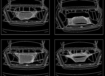
CARGO NET (if so equipped) The cargo net helps keep packages in the cargo area from moving around while the vehicle is in motion. To install the cargo net, attach the hooks to the retainers. To remove the cargo net, detach the hooks from the cargo net retainers.
2-30 Instruments and controls
WIC0190
Z X
WINDOWS
WARNING
POWER WINDOWS
c Properly secure all cargo to help pre-
vent it from sliding or shifting.
c Be sure to secure hooks into the retainers. The cargo restrained in the net must not exceed 30 lbs. (13.6 kg) or the net may not stay secured.
WARNING
c Make sure that all passengers have their hands, etc. inside the vehicle while it is in motion and before clos- ing the windows. Use the window lock switch to prevent unexpected use of the power windows.
c Do not leave children unattended in- side the vehicle. They could un- knowingly activate switches or con- trols and become trapped in a window. Unattended children could become involved in serious acci- dents.
LIC0177
If
The power windows operate when the igni- tion key is in the ON position, or for about 45
seconds after the ignition key is turned to the OFF position. the driver’s or front passenger’s door is opened during this pe- riod of about 45 seconds, power to the windows is cancelled. To open a window, press down on the switch. To close a win- dow, pull up on the switch. To stop the opening or closing function at any time, simply release the switch. The driver side control panel is equipped with switches to open or close all of the windows.Instruments and controls 2-31
Z X
LIC0178
LIC0179
The front and rear passenger window switches operate only the corresponding passenger window. To open the window, press down on the switch. To close the window, pull up on the switch. Locking passenger windows When the power window lock switch on the driver side control panel is pushed in, only the driver side window can be opened or closed. Push it in again to cancel this func- tion.
2-32 Instruments and controls
Automatic operation To fully open the driver or passenger side window, press the window switch down to the second detent and release it; it need not be held. The window automatically opens all the way. To stop the window, lift the switch up while the window is opening. Auto-reverse function If the control unit detects something caught in the window as it is closing, the window will be immediately lowered. The auto-reverse function can be activated
when the window is closed by automatic operation when the ignition key is in the ON position or for 45 seconds after the ignition key is turned to the OFF position. Depending on the environment or driv- ing conditions, the auto-reverse function may be activated if an impact or load similar to something being caught in the window occurs.
WARNING
There are some small distances imme- diately before the closed position which cannot be detected. Make sure that all passengers have their hands, etc., inside the vehicle before closing the window.
Z X
SUNROOF (if so equipped)
LIC0145
The sunroof only operates with the ignition key in the ON position. NOTE: If the battery is discharged or is discon- nected, the sunroof may not operate cor- rectly, and must be reset. From any sunroof position (full open, par- tially open, closed, partially vented and vented), push and hold the button in the forward position until the sunroof vents in the full-up position. This resets the sunroof motor memory and now the sunroof will operate correctly.
Sliding the sunroof To open the sunroof, push the switch to- ward DOWN/OPEN. To close the sunroof, push the switch to- ward UP/CLOSE. Tilting the sunroof Close the sunroof by pushing the switch toward UP/CLOSE. Release the switch, then push the UP/CLOSE switch to tilt the sunroof up. To tilt the sunroof down, push the switch toward DOWN/OPEN. Sun shade Open and close the sun shade by sliding it forward or backward.
WARNING
c In an accident you could be thrown from the vehicle through an open sunroof. Always use seat belts and child restraints.
c Do not allow anyone to stand up or extend any portion of their body out of the opening while the vehicle is in motion or while the sunroof is clos- ing.
CAUTION
c Remove water drops, snow,
ice or sand from the sunroof before opening. c Do not place heavy objects on the
sunroof or surrounding area.
Instruments and controls 2-33
Z X
INTERIOR LIGHT
MAP LIGHTS
−remain on for a maximum of 30
seconds.
−driver’s door is opened. −remain on for a maximum of 30
seconds after driver’s door is closed. −ignition key is removed from keycylinder
−remain on for a maximum of 30
seconds.
The lights will go off when the ignition key is in the ON position, or the driver’s door is closed and locked. The lights will also go off after 10 minutes while doors are open. c When the switch is in the ON position, the interior light illuminates, whether any door is open or closed.
CAUTION
Do not use for extended periods of time with the engine stopped. This could result in a discharged battery.
IC1235M
The interior light operates regardless of ignition key position. The interior light has a three-position switch. c When the switch is in the OFF position, the interior light does not illuminate, re- gardless of door position.
c When the switch is in the center j position, the front and rear personal lights will illuminate under the following conditions:
−driver’s door is unlocked.
2-34 Instruments and controls
Z X
LIC0147
LIC0146
To turn on the map lights, press the switches. To turn them off, press the switches again.
CAUTION
Do not use for extended periods of time with the engine stopped. This could result in a discharged battery.
TRUNK LIGHT
The light illuminates when the trunk lid is opened. When the trunk lid is closed, the light goes off.
HOMELINKT UNIVERSAL TRANSCEIVER (if so equipped) The HomeLinkT Universal Transceiver pro- vides a convenient way to consolidate the functions of up to three individual hand-held transmitters into one built-in device. HomeLinkT Universal Transceiver: c Will operate most Radio Frequency (RF) devices such as garage doors, gates, home and office lighting, entry door locks and security systems.
c Is powered by your vehicle’s battery. No separate batteries are required. the vehicle’s battery is discharged or is dis- connected, HomeLinkT will retain all pro- gramming.
If
Once the HomeLinkT Universal Trans- ceiver is programmed, retain the original transmitter for future programming pro- cedures (i.e., new vehicle purchases). Upon sale of the pro- grammed HomeLinkT Universal Trans- ceiver buttons should be erased for se- curity additional information refer to ‘‘Programming the HomeLinkT Universal Transceiver’’ later in this section.
the vehicle,
purposes.
For
Instruments and controls 2-35
Z X
WARNING
c Do not use the HomeLinkT Universal Transceiver with any garage door opener that lacks safety stop and reverse features as required by fed- eral safety standards. (These stan- dards became effective for opener models manufactured after April 1, 1982). A garage door opener which cannot detect an object in the path of a closing garage door and then au- tomatically stop and reverse, does not meet current federal safety stan- dards. Using a garage door opener without these features increases the risk of serious injury or death.
c During programming, your garage door or gate may open or close. Make sure that people and objects are clear of the garage door or gate that you are programming.
c Your vehicle’s engine should be turned off while programming the HomeLinkT Universal Transceiver.
2-36 Instruments and controls
SPA0609A
PROGRAMMING HomeLinkT 1. With the ignition key in the OFF position, press and hold the two outside buttons, and release when the indicator light be- gins to flash (approximately 20 seconds). This procedure erases the factory set default codes and does not have to be followed when programming additional hand-held transmitters.
2. Hold the end of the hand-held transmitter (from the device you wish to train) ap- proximately 2 to 5 inches (50 to 127 mm) away from the surface of HomeLinkT keeping the indicator light in view.
3. Using both hands, simultaneously push the hand-held transmitter button and the de- sired HomeLinkT button. Do not release the buttons until step 4 has been completed.
NOTE: Some garage door openers may require the procedures noted under ‘‘Canadian Programming’’. 4. The HomeLinkT indicator light will flash, first slowly and then rapidly. When the indicator light flashes rapidly, both buttons may be released. The rapid flashing light indicates the HomeLinkT Universal Trans- ceiver has been successfully programmed. To program the remaining two buttons, fol- low steps 2 through 4. If, after repeated attempts, you do not suc- cessfully program the HomeLinkT Universal Transceiver to learn the signal of the hand- held transmitter, refer to ‘‘Rolling Code Pro- gramming’’ later in this section. PROGRAMMING HomeLinkT FOR CANADIAN CUSTOMERS Prior to 1992, D.O.C. regulations required hand-held transmitters to stop transmitting after 2 seconds. To program your hand-held transmitter to HomeLinkT, continue to press
Z X
and hold the HomeLinkT button (note step 2
through 4 under ‘‘Programming HomeLinkT’’) while you press and re-press (‘‘cycle’’) your hand-held transmitters every 2 seconds until the indicator light flashes rapidly (indicating successful programming). NOTE: If programming a garage door opener, etc., it is advised to unplug the device during the ‘‘cycling’’ process to prevent possible dam- age to the garage door opener components. OPERATING THE HomeLinkT UNIVERSAL TRANSCEIVER The HomeLinkT Universal Transceiver (once programmed) may now be used to activate the garage door, etc. To operate, simply press the appropriate programmed HomeLinkT Universal Transceiver button. The red indicator light will illuminate while the signal is being transmitted. PROGRAMMING TROUBLE- DIAGNOSIS If the HomeLinkT does not quickly learn the hand-held transmitter information: c replace the hand-held transmitter batter-ies with new batteries.
c position the hand-help transmitter with its battery area facing away from the HomeLinkT surface.
c press and hold both the HomeLinkT and hand-held transmitter buttons without in- terruption.
c position the hand-held transmitter 2 to 5
inches (50 to 127 mm) away from the HomeLinkT surface. Hold the transmitter in that position for up to 15 seconds. If HomeLinkT is not programmed within that time, try holding the transmitter in another position - keeping the indicator light in view at all times.If you continue to have programming diffi- culties, please contact the NISSAN Con- sumer Affairs Department. The phone num- bers are located in the Foreword of this owner’s manual. CLEARING THE PROGRAMMED INFORMATION Individual buttons cannot be cleared, how- ever to clear all programming, press and hold the two outside buttons and release when the indicator light begins to flash (approximately 20 seconds)
ROLLING CODE PROGRAMMING Rolling code garage door openers (or other rolling code devices) which are ‘‘code pro- tected’’ and manufactured after 1996, may be determined by the following: A. Reference the garage door opener Own-
er’s Manual for verification.
B. The hand-held transmitter appears to program the HomeLinkT Universal Transceiver but does not activate the garage door.
C. Press and hold the trained HomeLinkT button. If the garage door opener has the rolling code feature, the HomeLinkT indi- cator light will flash rapidly, then remains on after 2 seconds.
To program the HomeLinkT Universal Transceiver to a garage door opener with the rolling code feature, follow these instruc- tions after completing the ‘‘Programming HomeLinkT’’ (the aid of a second person may make the following procedures quicker and easier). 1. Locate the training button on the garage door opener motor unit. Exact location the button may vary by and color of Instruments and controls 2-37
Z X
there is garage door opener brand. difficulty locating the training button, ref- erence the garage door opener Owner’s Manual.
If
2. Press the training button on the garage door opener motor unit (which may acti- vate a training light).
NOTE: Following step 2, there are 30 seconds in which to initiate step 3. 3. Firmly press and release the pro- grammed HomeLinkT button. Press and release the HomeLinkT button a second time to complete the training process. (Some garage door openers may require you to do this procedure a third time to complete the training.)
The garage door opener should now recog- nize the HomeLinkT Universal Transceiver and activate when the HomeLinkT button is pressed. The remaining two buttons may now be programmed (if not yet pro- grammed, follow steps 2 through 4 in the ‘‘Programming HomeLinkT’’ procedures earlier in this section).
2-38 Instruments and controls
REPROGRAMMING A SINGLE HomeLinkT BUTTON To reprogram an HomeLinkT Universal Transceiver button, complete the following. 1. Press and hold the desired HomeLinkT button. Do not release the button until step 4 has been completed.
2. When the indicator light begins to flash slowly (after 20 seconds), position the hand-held transmitter 2 to 5 inches (50 to 127 mm) away from the HomeLinkT sur- face.
3. Press and hold the hand-held transmitter
button.
4. The HomeLinkT indicator light will flash, first slowly and then rapidly. When the indicator light begins to flash rapidly, release both buttons.
The HomeLinkT Universal Transceiver but- ton has now been reprogrammed. The new device can be activated by pushing the HomeLinkT button that was just pro- grammed. This procedure will not affect any other programmed HomeLinkT buttons.
IF YOUR VEHICLE IS STOLEN If your vehicle is stolen, you should change the codes of any non-rolling code device that has been programmed into HomeLinkT. Consult the Owner’s Manual of each device or call the manufacturer or dealer of those devices for additional information. When your vehicle is recovered, you will need to reprogram the HomeLinkT Uni- versal Transceiver with your new trans- mitter information. FCC Notice: This device complies with FCC rules part 15. Operation is subject to the following two conditions: (1) This device may not cause harmful interference and (2) This device must accept any interference that may be received, including interference that may cause undesired operation. This transmitter has been tested and complies with FCC and DOC/MDC rules. Changes or modifications not expressly approved by the party responsible for compliance could void the user’s author- ity to operate the device. DOC: ISTC 1763K1313
FCC I.D. CV2V67690Z X
3 Pre-driving checks and adjustments
Keys .......................................................................3-2
Nissan vehicle immobilizer system (NVIS) keys .......................................................3-2
Doors......................................................................3-2
Locking with key................................................3-3
Locking with inside lock knob............................3-3
Locking with power door lock switch.................3-4
Child safety rear door lock ................................3-4
Remote keyless entry system (if so equipped)......3-5How to use remote keyless entry system ...............................................................3-5
Battery replacement ..........................................3-8
Hood.......................................................................3-9
Trunk lid................................................................3-10
Opener operation ............................................3-10Key operation ..................................................3-11
Interior trunk lid release...................................3-11
Fuel filler lid..........................................................3-12
Opener operation ............................................3-12
Fuel filler cap...................................................3-12
Steering wheel .....................................................3-13
Tilt operation....................................................3-13
Telescopic operation .......................................3-14
Sun visors.............................................................3-14
Vanity mirrors ..................................................3-14
Mirrors ..................................................................3-15
Inside mirror.....................................................3-15
Automatic anti-glare inside mirror (if so equipped)................................................3-15
Outside mirror remote control .........................3-16Z X
KEYS
DOORS
WPD0013
NISSAN VEHICLE IMMOBILIZER SYSTEM (NVIS) KEYS You can only drive your vehicle using the master or valet keys which are registered to the Nissan Vehicle Immobilizer System components in your vehicle. These keys have a transponder chip in the key head. The master key can be used for all the locks. The valet key cannot be used for the trunk lid glove box lock or rear seatback lock. To protect belongings when you leave a key with someone, give them the valet key only. 3-2 Pre-driving checks and adjustments
WARNING
c Always have the doors locked while driving. Along with the use of seat belts, this provides greater safety in the event of an accident by helping to prevent persons from being thrown from the vehicle. This also helps keep children and others from unintentionally opening the doors, and will help keep out intruders.
c Before opening any door, always look for and avoid oncoming traffic. c Do not leave children unattended in- side the vehicle. They could un- knowingly activate switches or con- trols. Unattended children could become involved in serious acci- dents.
Never leave these keys in the vehicle. Record the key number on the key number plate supplied with your keys and keep it in a safe place (such as your wallet), not in the vehicle. NISSAN does not record any key numbers so it is very important to keep track of your key number plate. A key number is only necessary when you have lost all keys and do not have one to duplicate from. If you still have a key, this key can be duplicated by your NISSAN dealer. Nissan Vehicle Immobilizer System KEY - Master and Valet keys: The key number is necessary when you need extra Nissan Vehicle Immobilizer Sys- tem keys. As many as 5 Nissan Vehicle Immoblizer System keys can be used with one vehicle. New keys must be registered to the Nissan Vehicle Immoblizer System components in your vehicle by your NISSAN dealer. At this time, you should bring all Nissan Vehicle Immobilizer System keys that you have to your NISSAN dealer for registration. This is because the regis- tration process will erase all memory of the Nissan Vehicle Immobilizer System compo- nents.
Z X
Opening and closing windows The driver’s door key operation allows you to open and close the front door windows simultaneously. c To open the windows, turn the driver’s door key to the rear of the vehicle for longer than 1 second after the door is unlocked.
c To close the windows, turn the driver’s door key to the front of the vehicle for longer than 1 second after the door is locked.
The door windows will open or close while turning the driver’s door key. This function will operate for 45 seconds after the ignition switch is turned off unless either front door is opened.
LPD0067
LOCKING WITH KEY The power door lock system allows you to lock or unlock all doors simultaneously. Turning the front door key to the front of the vehicle locks all doors. Turning the front door key one time to the rear of the vehicle unlocks the corresponding door. From that position, returning the key to neutral (where the key can only be removed and inserted) and turning it to the rear again within 5 seconds unlocks all doors.
LPD0068
LOCKING WITH INSIDE LOCK KNOB To lock a door without the key, move the inside lock knob to the lock position. When locking a door this way, be certain not to leave the key inside the vehicle.
Pre-driving checks and adjustments 3-3
Z X
LPD0069
LPD0070
APD1010
LOCKING WITH POWER DOOR LOCK SWITCH To lock all the doors without a key, push the door lock switch (driver or front passenger side), to the lock position. When locking the door this way, be certain not to leave the key inside the vehicle. When the power door lock switch (driver or passenger side) is moved to the lock posi- tion with the key in the ignition and any door open, all doors will lock and then unlock automatically.
3-4 Pre-driving checks and adjustments
CHILD SAFETY REAR DOOR LOCK Child safety locks help prevent rear doors from being opened accidentally, especially when small children are in the vehicle. The child safety lock levers are located on the edge of the rear doors. When the lever is in the lock position, the door can be opened only from the outside.
Z X
REMOTE KEYLESS ENTRY SYSTEM (if so equipped)
It is possible to lock/unlock all doors, turn the interior light on and activate the panic alarm by using the remote controller from outside the vehicle. Be sure to remove the key from the vehicle before locking the doors. The keyfob can operate at a distance of approximately 33 ft (10 m) from the vehicle. The effective distance depends on the con- ditions around the vehicle. As many as five keyfobs can be used with one vehicle. For information concerning the purchase and use of additional keyfobs, contact an authorized NISSAN dealer.
CAUTION
Listed below are conditions or occur- rences which will damage the keyfob: c Do not allow the keyfob to become
wet.
c Do not drop the keyfob. c Do not strike the keyfob sharply
against another object.
c Do not place the keyfob for an ex- tended period in an area where tem- peratures exceed 140°F (60°C).
HOW TO USE REMOTE KEY- LESS ENTRY SYSTEM Locking doors 1. Close all windows. 2. Remove the key from the ignition switch. 3. Close all doors.