- 2008 Mini Cooper Owners Manuals
- Mini Cooper Owners Manuals
- 2007 Mini Cooper Owners Manuals
- Mini Cooper Owners Manuals
- 2004 Mini Cooper Owners Manuals
- Mini Cooper Owners Manuals
- 2005 Mini Cooper Owners Manuals
- Mini Cooper Owners Manuals
- 2006 Mini Cooper Owners Manuals
- Mini Cooper Owners Manuals
- 2003 Mini Cooper Owners Manuals
- Mini Cooper Owners Manuals
- 2009 Mini Cooper Owners Manuals
- Mini Cooper Owners Manuals
- 2002 Mini Cooper Owners Manuals
- Mini Cooper Owners Manuals
- Download PDF Manual
-
91
BRAKE FLUID
Warning lamp
If the brake warning lamp comes on with the parking brake released: The brake fluid level is too low, see
page 15.
Brake warning lamp for Canadian models.
Adding brake fluid To add brake fluid or to determine and correct the cause of brake fluid loss, consult your MINI center. Your MINI center is familiar with the specifications for factory- approved brake fluids (DOT 4).
92
Brake fluid loss may result in extended brake pedal travel. If this occurs, refer to the information on page 79.
Brake fluid is hygroscopic, that is, it absorbs moisture from the air over
time. In order to ensure the brake system’s safety and reliability, have the brake fluid changed every two years by a MINI center, see also page 57 and the Service and Warranty Information Booklet (US models)/ Warranty and Service Guide Booklet (Cana- dian models). Brake fluid is toxic and also damages vehicle paintwork. Always store brake fluid in tightly-closed original containers kept well away from the reach of children. Do not spill the brake fluid and do not fill the brake fluid reservoir beyond the "MAX" mark. The brake fluid could ignite upon contact with hot engine parts and cause serious burns.<
Comply with the applicable environ- mental laws regulating the disposal
of brake fluid.<
MINI MAINTENANCE SYSTEM
The MINI Maintenance System has been designed as a reliable means of providing maximum driving and operating safety — and as cost-effectively as possible for you. Please bear in mind that regular mainte- nance is not only necessary for the safety of your vehicle, but also plays a significant role in maintaining the resale value of the vehicle.
Service Interval Display While conventional systems specify main- tenance according to rigid distances driven, the MINI Maintenance System takes account of the operating conditions of the vehicle, for distances can be driven in many different ways: From the point of view of maintenance, 60.000 miles (100.000 km) of short- distance driving cannot be regarded in the same way as 60.000 miles (100.000 km) of long-distance highway travel. The condition-based MINI Maintenance System includes the Engine Oil Service and Inspections I and II. Determining the maintenance intervals according to the actual use of the vehicle covers every kind of operating situation. People who drive very little — much less than 6.000 miles (10.000 km) per year — should have the engine oil changed at least every 2 years since oil deteriorates over time, regardless of use. For more information on the Service Interval Display, see page 57.
Service and Warranty Information Booklet (US models)/Warranty and Service Guide Booklet (Canadian models) For additional information on maintenance intervals and procedures, please refer to the Service and Warranty Information Booklet (US models) or the Warranty and Service Guide Booklet (Canadian models). As a precaution against rust, it is advisable to have the body checked for damage from rocks or gravel at the same time, depending upon operating conditions.
Have your vehicle’s maintenance and repairs performed at your MINI
center. Be sure that all maintenance work is confirmed in the Service and Warranty Information Booklet (US models) or the Warranty and Service Guide Booklet (Cana- dian models). These entries are your proof that the vehicle has received regular main- tenance. They are also a requirement for warranty claims.<
93
CARING FOR YOUR VEHICLE
Suitable car-care products
Rod antenna
Use the cleaning and car-care prod- ucts available at your MINI center.<
Washing your vehicle You can wash your new MINI from the outset in automatic car washes, though you should use brushless car washes.
When using steam jets or high-pres- sure washers, ensure that you keep
the jets sufficiently far away from the vehicle. If the jet is too close or the pressure is too high, this can lead to damage or initial damage that can develop into more serious damage. Water that enters vehicle components can lead to damage over the long term.<
After washing the vehicle, apply the brakes briefly to dry them, otherwise
water can reduce braking efficiency over the short term and the brake rotors can corrode. <
Switch the rain sensor off when passing through an automatic car wash, see page 51. Failure to do so could result in damage caused by undesired wiper activation.<
If necessary, before entering a car wash or garage with elevator ramp for example, remove the rod antenna. To do so, grip the rod antenna at the base and unscrew it from the antenna foot by turning it to the left.<
Headlamps
When cleaning the headlamps, please observe the following: do not clean by wiping with a dry cloth (scratches). Never use abrasives or strong solvents to clean the covers. Remove dirt and contami- nation (such as insects) by soaking with shampoo and then rinsing with plenty of water. Always use a deicer spray to remove accumulated ice and snow — never use a scraper.<
Vehicle paintwork Regular care contributes greatly to driving safety and value retention. Environmental influences varying from one region to the next can affect the vehicle paintwork. Please base the frequency and scope of car care on these various influ- ences.
Care of upholstery Depressions that come about on the uphol- stery material of the seats in daily use can be brushed out using a slightly damp brush against the grain. The fact that velour lays down is not a quality defect, but rather is inevitable in the case of home textiles or clothing mate- rials. In the case of strong sunlight and longer parking periods, cover the seats or all windows to prevent discoloration.
Care of special parts > Light-alloy wheels:
Use wheel cleaner especially during the winter months, but do not use any aggressive, acidic, strong alkali or rough cleansers or steam jets above 140 7 (60 6) (observe the manufacturer’s operating instructions)
> Chrome parts* such as cooler grille, door
handles, etc.: Especially if exposed to road salt, care- fully clean these parts with plenty of water and possibly with a shampoo addi- tive. For additional treatment, use chrome polish
94
CARING FOR YOUR VEHICLE
> Rubber parts:
Treat only with water or rubber care products
> Plastic parts, imitation leather surfaces, headliner, lamp glass, covering glass for the instrument cluster, as well as matt black molded parts: Clean with water and, if necessary, plastic care products. Do not dampen seats and the headliner. Never use solvents such as lacquer thinner, heavy- duty grease remover, fuel or similar
> Safety belts:
Only clean using mild soap, leaving the belts fitted; do not dry clean, as the fabric can be destroyed. Always unroll automatic safety belts when dry. Dirty safety belts prevent unrolling and thus negatively affect safety
> Floor carpets and floor mats*:
If heavily soiled, clean using interior cleaner. Floor mats can be removed to allow the interior to be cleaned
> Wiper blades:
Clean with soapy water. Replace wiper blades twice a year, before and after the cold season. This is particularly impor- tant on vehicles fitted with a rain sensor.
Cleaning agents can contain hazardous or health-damaging
substances. For this reason, always observe the warnings on the package. For interior cleaning, always open the doors or windows of the vehicle. Do not use any products (e.g. solvents) that are not intended for cleaning the vehicle.<
Use only wiper blades which have been approved by the manufac-
turer.<
Leather care The leather* used by the manufacturer is a high-quality natural product processed using state-of-the-art methods, and it will retain its quality level for many years if cared for appropriately. Regular cleaning and care are necessary, as dust and road dirt scratches in pores and creases and lead to heavy wear as well as premature brittleness of the leather surface. This is why you should use a cloth or vacuum cleaner to remove dust from the leather on a regular basis. As dirt and grease can slowly affect the protective layer of the leather, the cleaned leather surfaces must be treated with leather care agent. This also helps to avoid electrostatic charges.
95
VEHICLE IMMOBILIZATION
OBD INTERFACE SOCKET
TECHNICAL MODIFICATIONS
Your MINI center will be glad to advise you on what is important if the vehicle is to be decommissioned for longer than three months.
Any MINI center will be glad to inform you of the advisability, legal regulations and factory recommendations for technical modifications to the vehicle. To do so, they require the vehicle identification number from your vehicle documents.
The interface for onboard diagnostics is located on the driver’s side, behind a cover located beneath the instrument panel. The cover has the letters "OBD" on it. This interface makes it possible to access data on emissions-related components using special equipment.
96
CALIFORNIA PROPOSITION 65 WARNING
California laws require us to state the following warning:
Engine exhaust, some of its constitu- ents, and certain vehicle components
contain or emit chemicals known to the State of California to cause cancer and birth defects or other reproductive harm.<
97
98
OVERVIEW
CONTROLS
OPERATION, CARE, MAINTENANCE
OWNER SERVICE PROCEDURES
TECHNICAL DATA
INDEX
99
Repairs
ONBOARD TOOL KIT
WINDSHIELD WIPER BLADES
Storage location The illustration shows an example of the tire change set. Depending on the level of equipment, your MINI is fitted with a special onboard tool kit stored at the following locations: Tire change set for space-saver spare tire: In the luggage compartment under the floor mat. Tool bag for safety tires: In the left of the luggage compartment, behind the side trim panel beside the first- aid kit, see page 113.
Windshield wiper 1. Rotate the wiper arm completely out
Rear window wiper 1. Rotate the wiper arm completely out
from the windshield
2. Set the wiper blade at an angle 3. Press the securing spring (arrow) 4. Unhook the wiper blade towards the
windshield
from the windshield
2. Turn the wiper blade as far as it will go
to the rear, see arrow
3. Press the wiper blade against the limit
and thus out of the mounting
5. Pull the wiper blade past the wiper arm
4. Press the new wiper blade into the
mounting.
toward the top
6. Insert the new wiper blade 7. Press into position until you hear it
engage.
Use only wiper blades which have been approved by the manufac-
turer.<
100
LAMPS AND BULBS
Proceed carefully when handling lamps and bulbs. If you are not familiar with any of the procedures, consult your MINI center.
Do not touch the glass portion of a new bulb with your bare hands since even small amounts of impurities burn into the surface and reduce the service life of the bulb. Use a clean cloth, paper napkin, or a similar material, or hold the bulb by its metallic base.<
Replacement bulbs are available from your MINI center.
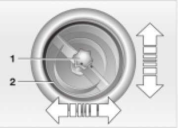
1 Low beams H7 bulb, 55 Watts
Whenever working on the electrical system, switch off the electrical
accessory you are working on or disconnect the cable from the negative terminal of the battery. Failure to do this could result in short circuits. To prevent injuries and damage, comply with any instructions provided by the bulb manufacturer.<
2 High beams H7 bulb, 55 Watts
The H7 bulb is pressurized. Therefore, wear safety glasses and protective
gloves. Failure to observe these precautions can result in physical injury if the bulb breaks.<
1. Pull off the cover panel of the corre-
sponding lamp
2. Press the securing wire outwards 3. Fold the securing wire downwards 4. Remove and replace the bulb.
When cleaning the headlamps, please observe the following: do not clean by wiping with a dry cloth (scratches). Never use abrasives or strong solvents to clean the covers. Remove dirt and contami- nation (such as insects) by soaking with shampoo and then rinsing with plenty of water. Always use a deicer spray to remove accumulated ice and snow — never use a scraper.<
Xenon lamps* The service life of these bulbs is very long and the probability of a failure is very low, provided that they are not switched on and off an unusual number of times. If one of these bulbs should nevertheless fail, it is possible to continue driving with great caution using the fog lamps, provided traffic laws in your area do not prohibit this.
Because of the extremely high volt- ages involved, any work on the xenon
lighting system should be carried out by technically-qualified personnel only. Other- wise, there is a risk of fatal injury.<
101
LAMPS AND BULBS
Fog lamps* H7 bulb, 55 Watts Please contact a MINI center in case of a malfunction.
Side turn signal indicators 5 Watt bulb 1. Press the bulb towards the rear of the
vehicle and remove
2. Remove and replace the bulb.
Side marker lamps Side marker lamps in the wheelhouse paneling of the bumper. Please contact a MINI center in case of a malfunction.
Turn signal indicators, front 21 Watt bulb 1. Open the hood 2. Reach into the opening for the turn
signal indicators from above
3. Apply gentle pressure to the bulb holder
while turning it to the left
4. Remove and replace the bulb.
Parking lamps and standing lamps 5 Watt bulb The parking lamps and standing lamps are integrated in the lamp housing of the turn signal indicator. 1. Turn the bulb holder to the left and pull
out
2. Remove and replace the bulb.
102
LAMPS AND BULBS
Tail lamps Rear lamp (3): 21/5 Watt bulb Other bulbs: 21 Watts 1 Rear fog lamp (not active) 2 Turn signal indicator 3 Rear lamp 4 Rear lamp/brake lamp
red yellow red red
Backup lamp Access to the lamp via the rear or underside of the bumper. 1. Press the clips together 2. Push the lamp out of the bumper 3. Apply gentle pressure to the bulb while
turning it to the left
4. Remove and replace the bulb.
To make this clear, the illustration shows a dismantled tail lamp with the bulb holder removed. All of the bulbs are integrated in the bulb holder. To reach the bulb holder, remove the cover of the side trim panel in the luggage compartment.
Replacing bulbs 1. Unplug the power supply 2. Release the bulb holder, see arrow, and
remove
3. Apply gentle pressure to the bulb while
turning it to the left
4. Remove and replace the bulb 5. Plug in the power supply receptacle 6. Press the bulb holder into position until
you hear it engage.
103
LAMPS AND BULBS
Center (high-mount) brake lamp LED strip on the tailgate. Please contact a MINI center in case of a malfunction.
License plate lamps 5 Watt bulb 1. Apply a screwdriver to the recess and
Interior lamps Interior lamp (6 Watt xenon bulb) 1. Press out the lamp cover with a screw-
lever out the lamp cover
2. Replace the bulb.
driver
2. Remove and replace the bulb.
Reading lamps (2 x 6 Watt xenon bulbs) 1. Press out the lamp cover with a screw-
driver
2. Unscrew the entire lamp with a screw-
driver
3. Remove the bulb from above and
replace.
104
LAMPS AND BULBS
Illuminated vanity mirror Lamps in the vanity mirror in the sun visor. Please contact a MINI center in case of a malfunction.
Luggage compartment lamps 5 Watt bulb 1. Press the lamp cover with a screwdriver
to the left and press out
2. Remove and replace the bulb.
Footwell lamps 5 Watt bulb 1. Press out the lamp cover with a screw-
driver
2. Remove and replace the bulb.
Glove compartment lamp 5 Watt bulb 1. Press out the lamp cover with a screw-
driver
2. Remove and replace the bulb.
105
REPAIRING A FLAT TIRE
CHANGING TIRES — MINI WITH SPACE-SAVER SPARE TIRE*
Safety measures in the event of a flat tire:
Stop the vehicle as far as possible from passing traffic. Switch on the hazard warning flashers. Turn the steering wheel to the straight- ahead wheel position and engage the steering lock. Engage the parking brake and shift into 1st or reverse gear (selector lever in P). All passengers should be outside the vehicle and well away from your imme- diate working area (behind a guardrail, for instance). If a warning triangle or portable hazard warning lamp is available, set it up on the roadside at an appropriate distance from the rear of the vehicle. Comply with all safety guidelines and regulations.<
In the event of a flat tire, different proce- dures should be followed depending on the equipment included in your MINI: > Vehicles with space-saver spare tire, see
next column
> Vehicles with safety tires, see page 110.
Additional safety measures in the event of a wheel change: change the wheel only on a level, firm surface which is not slippery. Avoid jacking the vehicle on a soft or slip- pery support surface (snow, ice, loose gravel, etc.), as either the vehicle or the jack could slip sideways. Do not use a wooden block or similar object as a support base for the jack, as this would prevent it from extending to its full support height and reduce its load-carrying capacity. Do not lie under the vehicle or start the engine when the vehicle is supported by the jack — risk of fatal injury.<
To change a space-saver tire, proceed as follows: > Remove the space-saver spare tire, see
page 107
> Prepare the vehicle, see page 108
> Jack up the vehicle, see page 108
> Fit the space-saver spare tire, seepage 109
> Tighten the lug bolts, see page 109
> Drive with space-saver spare tire, seepage 109.
106
Tire change set On vehicles with a space-saver spare tire, the tire change set is stored in the luggage compartment under the floor mat. 1 Chock, folding 2 Hubcap remover 3 Wheel stud wrench 4 Jack 5 Spanner 6 Tow fitting 7 Lifting handle
CHANGING TIRES — MINI WITH SPACE-SAVER SPARE TIRE*
Removing the space-saver spare tire The screw connection of the space-saver spare tire is in the luggage compartment under the floor mat, on the base of the storage compartment for the tire change set. 1. Loosen the screw connection using the
wheel stud wrench
2. Take out the cover panel
3. Screw the lifting handle from the
onboard tool kit onto the thread
4. Raise the lifting handle slightly
5. Squeeze the securing springs 6. The space-saver spare tire is released and must be held by the lifting handle 7. Lower the space-saver spare tire with
the lifting handle
8. Unscrew the lifting handle again
107
CHANGING TIRES — MINI WITH SPACE-SAVER SPARE TIRE*
Preparing the vehicle
Read and comply with the safety precautions provided on page 106.<
1. Secure the vehicle to prevent it from
rolling: Place the folding chock behind the front wheel on the other side of the vehicle; on downward inclines, place it in front of this wheel. If the wheel is changed on a surface with a more severe slope, take additional precautions to secure the vehicle from rolling
2. Loosen the lug bolts by a half turn.
Jacking up the vehicle 1. Place the jack at the jacking point closest
to the wheel. The jack base must be perpendicular to the surface beneath the jacking point
9. Pull out the space-saver spare tire towards the rear underneath the vehicle
10. Position the space-saver spare tire with
the valve facing upwards
11. Unscrew the valve extension from the
valve of the space-saver spare tire
12. Unscrew the dust cap from the exten-
sion and attach to the space-saver spare tire.
108
CHANGING TIRES — MINI WITH SPACE-SAVER SPARE TIRE*
2. Insert the jack head for jacking up in the
square recess of the jacking point
3. Jack the vehicle up until the wheel you are changing is raised from the ground.
The vehicle jack is designed for changing wheels only. Do not
attempt to raise another vehicle model with it or to raise any load of any kind. To do so could cause accidents and personal injury.<
Fitting the space-saver spare tire 1. Unscrew the lug bolts and remove the
wheel
2. Remove accumulations of mud or dirt
from the mounting surfaces of the wheel and hub. Clean the lug bolts
3. Fit the space-saver spare tire 4. Screw at least two lug bolts finger-tight
into opposite bolt holes
5. Screw in the remaining bolts 6. Tighten all the lug bolts firmly in a diag-
onal pattern
7. Lower the vehicle 8. Remove the jack.
Tightening the lug bolts Tighten the lug bolts in a diagonal pattern.
As soon as possible, have the secure seating of the lug bolts (tightening torque 72 ftlb (100 Nm)) checked using a calibrated torque wrench. Otherwise, a wheel that might come loose can lead to a severe accident.<
Replace the defective tire as soon as possible and have the new wheel/tire assembly balanced.
Driving with the space-saver spare tire Drive cautiously. Do not exceed a speed of 50 mph (80 km/h). You can expect changes in vehicle handling such as delayed braking response, longer braking distances, and changes in self- steering properties in marginal stability limits.
Only one space-saver spare tire may be mounted at one time. Reinstall
wheels and tires of the same size and speci- fication as soon as possible. Maintain prescribed tire pressures, see page 80.<
Only use full hubcaps approved by the manufacturer. Otherwise there is no guarantee that the hubcap fits securely. The hubcap must not be fitted to the space- saver spare tire, as it could be damaged.<
Check and correct the tire inflation pressure at the earliest opportu-
nity.<
109
Continuing driving with a damaged tire Driving can continue under certain condi- tions with safety tires, depending on the vehicle load and the severity of the tire damage, at a maximum speed of 50 mph (80 km/h). You can determine the possible mileage for continued driving on the basis of the following general indications: > Tire inflation pressure 0 bar (0 psi):
approx. 95 miles (150 km)
> Tire inflation pressure 0.5 bar — 1 bar (7.2 psi — 14.5 psi): approx. 300 miles (500 km)
> Tire inflation pressure greater than 1 bar (14.5 psi): approx. 600 miles (1,000 km).
FLAT TIRE — SAFETY (RUN-FLAT) TIRES*
Flat tire The yellow indicator lamp in the instru- ment cluster lights up to indicate a flat tire. In addition, a gong sounds, see pages 17, 62. 1. Reduce vehicle speed carefully to under 50 mph (80 km/h), avoiding hard brake applications and steering maneuvers
2. Do not exceed a speed of 50 mph
(80 km/h)
3. Identify damaged tires; check tire infla- tion pressures on all four wheels at the next opportunity, see page 80
4. Correct the tire inflation pressure if you wish to continue your journey and this is permitted, see next column
5. Have damaged tires changed by your
MINI center, see page 84.
Your MINI center has the information needed for working with safety tires and is equipped with the necessary special tools. They provide advice if you wish to replace the tires on your MINI or wish to re-equip from summer to winter tires — or vice versa, see also pages 80, 84, 85.<
For safety reasons, do not have a damaged safety tire repaired.<
You will recognize safety tires by a circular symbol containing the letters RSC on the side of the tire. Safety tires consist of self-contained tires and special rims. The tire reinforcement ensures that the tire retains some residual safety in the event of pressure drop and driving remains possible to a restricted degree.
The reinforcement on the flanks of the safety tires means that it is
usually not possible to detect an air loss from outside.<
110
BATTERY
Location in the MINI COOPER The battery is located in the engine compartment. Exact location, see page 87.
Location in the MINI COOPER S The battery is located in the luggage compartment under the floor mat.
Battery care The battery is absolutely maintenance-free, that is, the original electrolyte will normally last for the service life of the battery under moderate climatic conditions.
For all questions regarding the battery, please consult your MINI
center. <
Charging the battery Only charge the battery in the vehicle via the terminals in the engine compartment with the engine switched off, see "Jump- starting" on page 113.
Whenever working on the electrical system, disconnect the cable from
the negative terminal of the battery. Failure to do this could result in fire hazards or injury due to short circuits.<
Return used batteries to a recycling point or your MINI center. Maintain
the battery in an upright position for trans- port and storage. Secure the battery to prevent it from tilting during transport.<
111
FUSES
If an electrical device fails, switch it off and check the fuse. Plastic tweezers that you can use to pull fuses out of their sockets can be found in the fuse box of the interior, see next column.
In the engine compartment To the right of the battery. Open the cover panel of the fuse box. To do so, press the clip fastener.
In the interior On the left side of the footwell in the side trim panel. Open the cover panel of the fuse box. To do so, press the fastener.
Do not attempt to repair a blown fuse or replace it with a fuse of a different
color or amperage rating. To do this could cause a fire in the vehicle resulting from a circuit overload.<
If a fuse blows a second time, have the cause of the damage rectified by
your MINI center.<
112
WARNING TRIANGLE*
FIRST-AID KIT*
JUMP-STARTING
The warning triangle is located beneath the luggage compartment cover.
The first-aid kit is located together with the onboard tool kit in the left of the luggage compartment, behind the side trim panel.
Comply with legal requirements requiring you to carry a hazard
warning triangle in the vehicle.<
Some articles in the first-aid kit are perishable. For this reason, check the expiration dates of each of the items regu- larly, and replace any whose expiration dates have passed. Source: any pharmacy. Comply with legislation requiring you to carry a first-aid kit in the vehicle.<
Do not use spray starter fluids to start the engine. When your battery is discharged, you can use two jumper cables to start your vehicle with power from the battery in a second vehicle. By the same token, you can provide another vehicle with starting assistance. To do so, use only jumper cables with fully insulated terminal clamps.
Do not touch live wiring and cables on a running engine. There is a risk of fatal injury if you do this. Carefully observe the following instructions to avoid personal injury and/or damage to either vehicle or both vehicles.<
113
JUMP-STARTING
Preparation for jump-starting 1. Check whether the battery of the support vehicle has 12 Volts and approximately the same capacity (Ah) (printed on the battery)
2. Switch off the engine of the support
vehicle
3. Switch off any electrical systems and components in both vehicles — except for the hazard warning flashers of the support vehicle. > Do not disconnect the discharged battery from the vehicle electrical system
> Make certain that there is no contact
between the bodywork of the two vehicles — short circuit hazard!
4. With the battery of the MINI COOPER, remove the cover panel. To do so, press both clips at the same time or with the MINI COOPER S, open the cover of the positive terminal connection (for jump-starting)*, see arrow 1.
Connect the jumper cables
Adhere to the sequence also when providing support for other vehicles; failure to observe this procedure can lead to sparks at the terminals and pose an injury hazard.<
114
Performing the jump-start 1. Start the engine of the vehicle providing the current and allow to run at a fast idle speed for several minutes
2. Start the engine on the vehicle with the discharged battery in the usual manner. > If the first start attempt is not
successful, wait a few minutes before another attempt in order to allow the discharged battery to recharge.
On the MINI: Before disconnecting the jumper
cables, switch on the lighting, rear window defroster and the highest blower speed as well as the engine for at least approx. 10 seconds to prevent a voltage surge from the regulator to the electrical systems and components.<
3. Then disconnect the jumper cables in
the reverse order.
Depending on the cause of the malfunction, have the battery checked and recharged at your MINI center.<
1. On the MINI COOPER S, the positive
terminal connection (for jump-starting), see arrow 1, functions as the positive battery terminal. Use the jumper cable (+) to set up a connection between the positive terminal of the discharged battery and the positive terminal of the support battery
2. Use the second jumper cable (—) to set
up the connection between the negative terminals of both vehicles. To do so: > Connect one terminal clamp to the
negative terminal and/or to an engine or body ground of the support vehicle > Connect the second terminal clamp to
the negative terminal of the battery and/or to an engine or body ground of the vehicle to be started. For the MINI, see arrow 2.
TOW-STARTING AND TOWING
Screw the tow fitting in until it bottoms firmly. If this is not done, the
threads could be damaged. Never attach tie-down hooks, chains, straps, or tow hooks to tie rods, control arms, or any other part of the vehicle suspension, as severe damage to these components will occur, leading to possible accidents.<
For towing, use either a tow bar or a nylon rope or nylon belts that prevent sudden jerking movements.
Tow fitting The screw-in tow fitting is stored in the onboard tool kit; be sure that it remains in the vehicle at all times. This fitting is designed for installation in the tow sockets located at the front and rear of the vehicle. It is intended for towing on paved road surfaces only.
Access to tow sockets Use a suitable object (e.g. credit card, screwdriver) to press out the covers from the recess.
Tow bars If the tow fittings of the two vehicles are not directly opposite one another, please note: > Clearance and maneuvering capability
will be strictly limited in corners
> The inclination of the tow bar generates lateral force (critical above all if the road surface is slippery).
Do not tow a vehicle that is heavier than the towing vehicle, otherwise it will no longer be possible to control vehicle response.<
115
TOW-STARTING AND TOWING
Tow-starting
Towing
On vehicles with Continuously Vari- able automatic Transmission (CVT), it is not permitted to start the engine by tow- starting. The transmission could be damaged. For jump-starting, see page 113.<
Only tow-start vehicles with a catalytic converter when the engine is cold, other- wise, unburned fuel in the catalytic converter could catch fire. It is better to use jumper cables. 1. Switch on the hazard warning flashers
(comply with national regulations)
2. Ignition key in position 2
3. Engage 3rd gear 4. Tow-start with the clutch pedal pressed 5. Slowly release the clutch 6. When the engine starts, press the clutchpedal again
7. Switch off the hazard warning flashers. Have the cause of the starting problems rectified by your MINI center.
Only tow vehicles with Continuously Variable automatic Transmission
(CVT) with the front wheels raised or on a special transport vehicle, otherwise the transmission can be damaged.<
1 Ignition key in position 1:
The brake lamps, turn signals, horn and windshield wipers can be operated
2 Switch on the hazard warning flashers
(comply with national regulations).
If the electrical system has failed, place some kind of warning on the towed vehicle, e.g. a sign or warning triangle in the rear window.
Ensure that if the electrical system has failed the ignition key is in posi- tion 1, otherwise the steering lock could engage and make it impossible to steer the vehicle. When the engine is not running, there is no power-assist. This means that greater effort is required for braking and steering.<
Towing with a commercial tow truck > Do not tow with sling-type equipment > Use a wheel-lift or flatbed carrier > Please comply with applicable towing
laws.
Never allow passengers to ride in a towed vehicle for any reason.<
116
W
117
118
OVERVIEW
CONTROLS
OPERATION, CARE, MAINTENANCE
OWNER SERVICE PROCEDURES
TECHNICAL DATA
INDEX
119
Data
ENGINE DATA
Displacement Number of cylinders Maximum output at engine speed Maximum torque at engine speed Compression ratio Stroke Bore Fuel-injection system
cu in/cmm
kW/bhp rpm lb ft/Nm rpm in/mm in/mm
MINI COOPER 97.52/1,598
85/115
6,000110/149
4,500
10.63.38/85.8
3.03/77MINI COOPER S
97.52/1,598
120/163
6,000
155/210
4,000
8.33.38/85.8
3.03/77Digital electronic engine-management system
120
DIMENSIONS
All dimensions specified in inches (millimeters). Smallest turning circle 35 ft (10.66 m).
121
WEIGHTS
MINI COOPER
MINI COOPER S
Curb weight, ready for operation, with 165 lbs./75 kg load, 90% full tank, options not included with manual transmission with Continuously Variable automatic Transmission (CVT) Approved gross vehicle weight with manual transmission with Continuously Variable automatic Transmission (CVT)
Approved front axle load Approved rear axle load Approved roof load (with special MINI roof rack) Luggage compartment capacity
lbs./kg lbs./kg
lbs./kg lbs./kg lbs./kg lbs./kg lbs./kg cu ft/liters
2,480/1,125
2,535/1,1503,263/1,480
3,318/1,505
1,918/870
1,543/700165/75
5.3/1502,678/1,215
—
3,461/1,570
—
1,962/890
1,675/760165/75
5.3/150122
CAPACITIES
Fuel tank Reserve Windshield washer/ headlamp cleaning system Cooling system including heater circuit
gal./liters gal./liters quarts/liters quarts/liters quarts/liters 5.6/5.3 MINI COOPER
approx. 13.2/50
approx. 2.1/8
approx. 2.6/2.5
approx. 2.6/2.56.3/6.0 MINI COOPER S
Engine oil and filter change
quarts/liters 4.7/4.5 MINI COOPER
4.7/4.5 MINI COOPER S
Manual transmission, incl. differential
quarts/liters approx. 2.1/2 MINI COOPER
Continuously Variable automatic Transmission (CVT), incl. differential
approx. 1.8/1.7 MINI COOPER S
quarts/liters approx. 4.2/4.0 MINI COOPER
Notes Fuel quality, see page 78
More details, see page 89
More details, see page 91
Longlife Oil More details, see page 89
Contact your MINI center for more details Contact your MINI center for more details123
ELECTRICAL SYSTEM
Battery 12V, 55 Ah
Spark plugs NGK BKR 6 EQUP
Original MINI parts and accessories as well as qualified advice is available
at your MINI center.<
124
W
125
126
OVERVIEW
CONTROLS
OPERATION, CARE, MAINTENANCE
OWNER SERVICE PROCEDURES
TECHNICAL DATA
INDEX
127
Index
Hilfsrahmen f(cid:159)r Querverweise
EVERYTHING FROM A TO Z
ABS (Antilock Brake
System) 16, 17, 78
Activated-charcoal filter 69 Adjusting
backrest 33 seats 31 steering wheel 35 thigh support 33
Air conditioner operation 65