- 2008 Mini Cooper Owners Manuals
- Mini Cooper Owners Manuals
- 2007 Mini Cooper Owners Manuals
- Mini Cooper Owners Manuals
- 2004 Mini Cooper Owners Manuals
- Mini Cooper Owners Manuals
- 2005 Mini Cooper Owners Manuals
- Mini Cooper Owners Manuals
- 2006 Mini Cooper Owners Manuals
- Mini Cooper Owners Manuals
- 2003 Mini Cooper Owners Manuals
- Mini Cooper Owners Manuals
- 2009 Mini Cooper Owners Manuals
- Mini Cooper Owners Manuals
- 2002 Mini Cooper Owners Manuals
- Mini Cooper Owners Manuals
- Download PDF Manual
-
To switch DSC back on Briefly press the switch once again. Indicator lamp goes out.
Indicator lamp
The indicator lamp on the instru- ment cluster will go out shortly after the ignition has been
switched on, see pages 16, 17.
If the indicator lamp flashes: DSC controls the drive and braking forces.
If the indicator lamp fails to go out after the engine is started, or if it
comes on during normal driving and stays on: If the system is either defective or was switched off with the button, then the stabilizing applications described are no longer available. The vehicle will remain completely operational, however, without DSC. In the event of a malfunction, please see your MINI center, see pages 16, 17.<
61
FLAT TIRE MONITOR
The concept The tire inflation pressure is determined from the signals of the ABS sensors. The system provides an alert whenever the tire inflation pressure drops below the pressure in any other tire.
Requirement So that the system can "familiarize" itself with the correct inflation pressure, please do the following: 1. Check the tire inflation pressure in all
tires
2. Compare them with the inflation pres- sure table, see page 81, and adjust the pressures if necessary 3. Initialize the system.
Check the tire inflation pressure regularly and correct it if necessary,
see page 80.<
Flat tire
The indicator lamp in the instru- ment cluster informs you by flashing when the tire inflation
pressure of a tire drops in relation to any other tire. In addition, an acoustic signal is sounded. > Vehicles with safety (run-flat) tires, see
notes on pages 110, 80, 84
> Vehicles with normal tires, see notes on
pages 106, 80.
The Flat Tire Monitor cannot alert you to severe and sudden tire damage
caused by external factors. Another factor which the Flat Tire Monitor does not recog- nize is the balanced and very gradual pres- sure loss that takes place in all tires over an extended period of time.<
Malfunctions As long as there is still a malfunction, the yellow indicator lamp on the instrument cluster will stay lit up. The indicator lamp also lights up in the event of a system malfunction. Please contact your MINI center in these cases.
62
Initializing the system Only initialize the system if the inflation pressure, e. g. after a tire change, has been corrected. 1. Ignition key in position 2 2. Press the button long enough for the
yellow indicator lamp in the instrument cluster to light up for a few seconds
3. Start the engine. After a few minutes driving time, the Flat Tire Monitor sets the current inflation pres- sure in the tires as the target values to be monitored.
FLAT TIRE MONITOR
PARK DISTANCE CONTROL (PDC)*
Do not initialize the system when snow chains are fitted. When driving with snow chains, false alarms can occur or pressure losses might not be detected.<
In the following situations false alarms can also occur under certain
circumstances or the detection of inflation pressure loss can be delayed: > When driving on roads covered with
snow or on other slippery road surfaces > A sporty driving style (slip at the driven
wheels, high lateral accelerations).<
The concept The PDC assists you when you back into a parking space. A signal warns you of the distance to an obstacle. To do this, four ultrasonic sensors in the rear bumper measure the distance to the nearest object. The range for the sensors located at both rear corners ends approx. 2 ft (60 cm) behind the bumpers. The range for the two middle sensors is slightly less than 5 ft (1.5 meters). The system starts to operate automatically about one second after you select reverse with the ignition key in position 2. PDC is deactivated when you shift back out of reverse.
Acoustical signals The distance to the nearest object is indi- cated by a tone sounding at various inter- vals. As the distance between vehicle and object decreases, the intervals between the tones become shorter. A continuous tone indicates the presence of an object less than 9 in (20 cm) away. The warning signal is canceled after approx. three seconds if the distance to the obstacle remains constant during this time (if you are moving parallel to a wall, for instance).
System malfunctions will be indicated by a continuous high-pitched tone when the system is activated the first time. Please have your MINI center resolve the problem.
Even with PDC, final responsibility for estimating the distance between the
vehicle and any obstructions always remains with the driver. Even when sensors are involved, there is a blind spot in which objects cannot be detected. Moreover, the detection of obstructions can approach the physical limits of ultrasonic measurement, as occurs e. g. in the case of thin and wedge-shaped objects. Certain sources of sound, such as a loud radio, could drown out the PDC signal tone.<
Keep the sensors clean and free of ice or snow in order to ensure that they
will continue to operate effectively. Do not apply high pressure spray to the sensors for a prolonged period of time. Always maintain a distance of more than 4 in (10 cm).<
63
AIR CONDITIONER SYSTEM
1 Air onto the windshield and onto the
side windows
2 Air for the upper body area 66
3 Air for the front and rear footwells4 Temperature 65
5 Windshield heating 65
6 Blower for air supply 65
7 Air conditioner 658 Air distribution 9 Recirculated-air mode 65
10 Rear window defroster 6564
AIR CONDITIONER SYSTEM
Air supply
Rear window defroster
Air conditioner
You can select blower speeds from 1 to 4. Position 0: blower is switched off. The button for recirculated-air mode fully blocks
the supply of air from outside. Heating and ventilation operate as of posi- tion 1.
Temperature
Turn to the right (red) to increase the temperature of the passenger compartment. Rapid heating: turn to the
extreme right. Then select a pleasant inte- rior temperature.
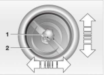
Air distribution
Air distribution in upper body , upper body region region and footwell footwell and windows and
, footwell
windows All intermediate positions are possible, see illustration and overview on page 64.
Rear window defroster switched on: Indicator lamp lights up.
As long as the indicator lamp is lit, the heating operates at high power output (rapid defrosting). Indicator lamp goes out. The heating continues to run with reduced power output and then switches itself off automatically.
Windshield heating*
Windshield heating switched on: Indicator lamp lights up. As long as the indicator lamp is
lit, the heating operates at high power output (rapid defrosting). Indicator lamp goes out. The heating continues to run with reduced power output and then switches itself off automatically.
Air conditioner operation switched on: Indicator lamp lights up.
The air is cooled and dehumidified and — depending on the temperature setting — rewarmed. After the engine start, the windshield can fog over briefly.
Condensation forms in the air condi- tioner system during operation, and
then exits under the vehicle. Traces of condensed water under the vehicle are therefore normal.<
Recirculated-air mode
Supply of outside air into the vehicle is blocked: indicator lamp lights up.
The air within the vehicle is recirculated.
Do not run the recirculated-air mode for longer than approx. 30 minutes, as otherwise the air quality in the interior will deteriorate.<<<<
If the windows fog over in the recir- culated-air mode, switch the recircu-
lated-air mode off and increase the air supply as required.<<<<
65
AIR CONDITIONER SYSTEM
Microfilter The microfilter removes dust and pollen from the incoming air. Your MINI center will replace it during routine maintenance. A substantial reduc- tion in the air supply indicates that the filter must be replaced before scheduled maintenance.
Draft-free ventilation Air supply for the upper body area: Button 1: open and close the vent outlets as required by turning. The points indicate the position in each case. Vent 2: change the direction of the airflow by swiveling.
Defrosting and demisting the windshield and side windows 1. Set the rotary blower speed control for
the airflow rate to position 4
2. Turn the rotary temperature control
completely to the right (red)
3. Rotary control for air distribution in posi-
tion
4. To defrost the rear window: switch on
the rear window defroster and, if required, the windshield heating.
66
AUTOMATIC CLIMATE CONTROL*
1 Air onto the windshield and onto the
5 Interior temperature sensor — please
side windows
keep clear and unobstructed
2 Air for the upper body area, see page 69
3 Air for the front and rear footwells 4 Rear window and windshield6 Recirculated-air mode 68
7 Air conditioner 68
8 Automatic air distribution andheating 68
supply 68
10 Temperature 68
11 Display for temperature and airsupply 68
12 Blower for air supply 69
13 Defrosting and demisting thewindshield and side windows 69
9 Switching the automatic climate
14 Individual air distribution 69
control on/off 68
67
AUTOMATIC CLIMATE CONTROL*
Automatic air distribution and supply
Automatic program (AUTO): Indicator lamp lights up.
Automatic adjustment of the air distribu- tion and the air supply and adaptation of the specified temperatures to external influences (outside temperature and sunlight). In the automatic program (AUTO), the air conditioner is activated automatically.
After the engine start, the windshield can fog over briefly. Switching on the air condi- tioner reduces condensation on the windows.
Condensation forms in the air condi- tioner system during operation, and
then exits under the vehicle. Traces of condensed water under the vehicle are therefore normal.<
Switching the automatic climate control on/off
The blower, heating and air condi- tioner are switched off.
To switch the automatic climate control on again: Press any button of the automatic climate control.
Recirculated-air mode
Supply of outside air into the vehicle is blocked:
Indicator lamp lights up. The air within the vehicle is recirculated. In the automatic program (AUTO) in hot weather conditions, the recirculated-air mode is activated temporarily to enable faster cooling.
Air conditioner
Air conditioner switched on: Indicator lamp lights up.
The air is cooled and dehumidified and — depending on the temperature setting — rewarmed. In the automatic program (AUTO), the air conditioner is activated automatically.
Do not run the recirculated-air mode for longer than approx. 30 minutes, as otherwise the air quality in the interior will deteriorate.<
If the windows fog over in the recir- culated-air mode, switch the recircu-
lated-air mode off and increase the air supply as required.<
Rear window defroster and windshield heating*
Rear window defroster and wind- shield heating switched on:
Indicator lamp lights up. As long as the indicator lamp is lit, the heating operates at high power output (rapid defrosting). Indicator lamp goes out. The heating continues to run with reduced power output and then switches itself off automatically.
Temperature
Setting the temperature: Move or turn the wheel in the appropriate direction to increase the temperature step by step.
The figures in the display provide a general indication of interior temperature. When you start the vehicle, the system ensures that the selected temperature is achieved as quickly as possible and then maintained.
Permanent heating with maximum power output at temperature selec-
tion "HI". Permanent cooling at "LO".<
68
AUTOMATIC CLIMATE CONTROL*
Air supply
Press the left or right half of the button: the air supply varies.
Defrosting and demisting the windshield and side windows Press the button briefly. The indicator lamp flashes.
Ice and condensation are removed from the rear window/windshield and side windows. The rear window defroster/windshield heating is switched on automatically. It can be switched off again separately. Press the button for a longer period. Only air to the windshield.
Individual air distribution
Combine the air distribution yourself. This switches off the automatic program.
Draft-free ventilation Air supply for the upper body area: Button 1: open and close the vent outlets as required by turning. The points indicate the position in each case. Vent 2: change the direction of the airflow by swiveling.
Microfilter/activated-charcoal filter The microfilter removes dust and pollen from the incoming air. The activated-char- coal filter provides additional protection by filtering gaseous pollutants from the outside air. Your MINI center replaces this combined filter as a standard part of your scheduled maintenance. A substantial reduction in the air supply indicates that the filter must be replaced before scheduled maintenance.
69
GLOVE COMPARTMENT
ASHTRAY/BEVERAGE HOLDER CIGARETTE LIGHTER
To open: Pull the handle. The light goes on.
To close: Fold the door up.
To prevent injury in the event of an accident, close the glove compart-
ment immediately after use.<
Ashtray The ashtray is located in one of the beverage holders in the center console. In the rear, an ashtray can also be fitted in the beverage holder at the end of the center console.
Beverage holders There are two beverage holders at the front of the center console. Another is located at the end of the center console.
From ignition key position 1: Press the cigarette lighter in. Remove as soon as the lighter jumps back out.
Hold or touch the hot cigarette lighter by the knob only. Holding or touching it in other areas could result in burns. <
Lighter socket Suitable for attaching power supplies for flashlights, car vacuum cleaners, etc., up to a rating of approx. 200 Watts at 12 Volts. Avoid damaging the socket with plugs of different shapes or sizes.
70
LUGGAGE COMPARTMENT COVER
FOLDABLE REAR BACKREST
When the tailgate is opened, the luggage compartment cover is also raised.
Never place heavy or hard objects on the luggage compartment cover, as
otherwise occupants could be injured during braking maneuvers.<
The warning triangle* is located beneath the luggage compartment
cover, see page 113. Comply with legal requirements requiring you to carry a hazard warning triangle in the vehicle.<
Removal To load bulky luggage, the compartment cover can be removed. 1. Remove the retaining straps on the
tailgate
2. Pull the luggage compartment cover out
towards the rear.
Unlock and fold 1. Pull lever 2. Fold the rear backrest forwards.
When folding the backrest back into its original position always ensure that the detent engages securely. A loose backrest might fail to prevent cargo from entering the passenger compartment during sudden braking or evasive maneu- vers, posing a potential hazard to occu- pants.<
71
LOADING CARGO
Stowing cargo > Load heavy cargo as far forward as
possible — directly behind the backrests — and as low as possible
> Cover sharp edges and corners > Do not pile objects higher than the top
edge of the backrest
> For very heavy loads when the rear seat is not occupied, secure each safety belt in the opposite buckle. This provides addi- tional stabilization for the rear backrests.
Securing the load > For small, light items, secure using the luggage compartment net* or elastic straps
> For large, heavy items, see your MINI
center for load-securing devices*. Lashing eyes are provided at the inner corners of the luggage compartment for attaching these load-securing devices
> Comply with the information enclosed
with the load-securing devices.
72
LOADING CARGO
ROOF-MOUNTED LUGGAGE RACK*
Always position and secure the load carefully. If you do not, it can
When loading a roof-mounted luggage rack, ensure that there is
endanger the passengers during braking or evasive maneuvers. Do not exceed the permissible gross weight and axle load, see page 122, otherwise the vehicle’s operating safety is no longer assured and you are in violation of the law. Do not stow heavy or hard objects in the passenger compartment without first securing them. Otherwise they would be thrown around during braking and evasive maneuvers and endanger the occupants.<
sufficient space for the movement of the sliding/tilt sunroof and that no objects protrude into the swiveling area of the tail- gate, as otherwise damage can occur.<
Do not secure the roof-mounted luggage rack to the trim panels/
strips: the lack of a secure hold could lead to damage or accidents.<
Special roof-mounted luggage racks for your MINI are available as acces-
sories from your MINI center.<
73
74
OVERVIEW
CONTROLS
OPERATION, CARE, MAINTENANCE
OWNER SERVICE PROCEDURES
TECHNICAL DATA
INDEX
75
Operation
BREAK-IN PROCEDURES
GENERAL DRIVING NOTES
To ensure that your vehicle provides maximum economy throughout a long service life, we request that you comply with the following information:
Engine Up to 1,200 miles (2,000 km): Attempt to constantly vary both vehicle and engine speed during these initial miles while remembering to avoid engine speeds in excess of 4,500 rpm and/or vehicle speeds of over 95 mph (150 km/h). Absolutely avoid using the full-throttle or kickdown position for the accelerator. Once you have driven 1,200 miles (2,000 km), both the engine and vehicle speed can be gradually increased. You should also comply with these break-in procedures if the engine has to be replaced at a later point.
Tires Due to technical factors associated with their manufacture, tires do not achieve their full traction potential until after an initial break-in period. We therefore ask you to drive with extra care during the first 200 miles (300 km).
Brake system Approx. 300 miles (500 km) must be driven before the brake pads and rotors achieve the optimum pad-surface and wear patterns required for trouble-free opera- tion and an extended service life.
Clutch Roughly 300 miles (500 km) must be driven before the clutch starts to operate at optimum efficiency. Remember to engage the clutch carefully during this initial period.
Parking the vehicle Condensation forms in the air conditioner system during operation, and then exits under the vehicle. Traces of condensed water under the vehicle are therefore normal.
Brakes
Do not rest your foot on the brake pedal while driving. Even light but
consistent pedal pressure can lead to high temperatures, brake wear and possibly even brake failure.<
Hydroplaning
When driving on wet or slushy roads, reduce road speed. If you do not, a
wedge of water can form between tires and road surface. This phenomenon is charac- terized by a partial or complete loss of contact between the tires and the road surface. The ultimate results are loss of steering and braking control.<
76
GENERAL DRIVING NOTES
REFUELING
Driving through water
Do not drive through water on the road if it is deeper than 1 ft (30 cm),
and then only at walking speed at the most. Otherwise, the vehicle’s engine, the electrical systems and the transmission may be damaged.<
Clothes hooks
When suspending clothing from the hooks, ensure that they will not
obstruct the driver’s vision. Do not hang heavy objects on the hooks. If you do so, they could cause personal injury during braking or evasive maneuvers.<
High temperatures
High temperatures occur in any vehicle equipped with a catalytic
converter. Do not remove the heat protec- tion plates fitted in the area of the exhaust system and do not apply body-cavity protectant to this area. When driving, standing at idle or when parking, take precautions to avoid contact between the hot exhaust system and easily flammable materials (grass, hay or leaves, for example). Such contact could lead to a fire, resulting in serious personal injury and property damage.<
Always switch off the engine before refueling. If you do not, fuel cannot
be filled into the tank and the "Service Engine Soon" lamp may come on.<
1. Open the fuel filler door 2. Turn the filler cap counterclockwise 3. Put the filler cap in the bracket attached
to the fuel filler door.
Always observe all applicable precau- tions and regulations when handling
fuels. Never carry spare fuel containers in your vehicle. Whether empty or full, these containers can leak, cause an explosion, and lead to fire in the event of a collision.<
Simple and environmentally friendly
Always observe all safety precautions posted at the service station when
handling fuel.<
When refueling, insert the filler nozzle completely into the filler pipe. Pulling the nozzle out of the pipe during refueling > results in premature pump shutoff > and will reduce the effect of the fuel vapor recovery system on the pump.
As long as the filler nozzle is used properly, the fuel tank is full whenever the nozzle shuts off the first time. Tank capacity: approx. 13.2 gallons (50 liters).
Close the fuel cap carefully after refuelling until a "click" is heard.
While closing, be sure not to squeeze the strap which is fastened to the filler cap. A loose or missing cap will activate the "Service Engine Soon" warning lamp.<
Refill early to avoid damaging the catalytic converter; never attempt to
drive to the last drop of fuel in the tank.<
77
FUEL SPECIFICATIONS
ANTILOCK BRAKE SYSTEM (ABS)
The engine uses lead-free gasoline only. Required fuel: > Premium Unleaded Gasoline, min. 91 AKI. AKI = Anti Knock Index.
Do not use leaded fuels. The use of leaded fuels will cause permanent
damage to the emissions-control system’s oxygen sensor and the catalytic converter.<
The concept The ABS keeps the wheels from locking while braking, thereby enhancing active driving safety. ABS also includes Electronic Brake Force Distribution (EBV).
Braking with ABS To achieve optimal performance from ABS when reacting to critical situations you should apply maximum pressure to the brake pedal ("panic stop"). Since the vehicle maintains steering responsiveness, you can nevertheless avoid possible obstacles with a minimum of steering effort. Pulsation of the brake pedal in conjunction with the sound of hydraulic regulation indi- cates to you that you are driving at the limit and reminds you to readapt your vehicle’s speed to road surface conditions.
78
Brake pads
For your own safety: use only brake pads that the manufacturer has
released for your particular vehicle model. The manufacturer cannot evaluate non- approved brake pads to determine if they are suited for use, and therefore cannot ensure the operating safety of the vehicle if they are installed.<
BRAKE SYSTEM
Brake fluid level If the brake fluid level is too low and brake pedal travel has become longer, there may be a defect in one of the brake system’s hydraulic circuits.
Proceed to the nearest MINI center. Higher brake application pressure
may be necessary under these conditions, there may be slight "pull" to one side, and brake pedal travel may be longer. Please remember to adapt your driving style accordingly.<
Disc brakes When the vehicle is driven only occasion- ally, during extended periods when the vehicle is not used at all, and in operating conditions where brake applications are less frequent, there is an increased tendency for corrosion of the brake rotors and accumulation of contamination on the brake pads. This occurs because the minimal pressure that must be exerted by the pads to clean the rotors by brake appli- cations is not reached. Corrosion on brake rotors is signaled by a running or pulsation during braking; even extended subsequent braking will not cure this phenomenon.
It is a good idea to periodically dry the brakes with a gentle application when driving in rain and on wet roads. Monitor traffic conditions to ensure that this maneuver does not endanger other road users. The heat generated in this process helps dry the brake pads and rotors to ensure that your brake system will respond with undiminished efficiency when you need it. Extended or steep mountain descents should be driven in the gear or in the driving position in which only minimal peri- odic brake application is required. This helps avoid placing excessive loads on the brake system. Stay within the allowable speed range, refer to page 55.
Do not coast with the clutch pressed or with the transmission or selector
lever in Neutral. Do not coast with the engine switched off. The engine provides no braking effect when the transmisson is in neutral and there is no power-assist for braking when the engine is switched off.<
79
TIRE INFLATION PRESSURE
Information for your safety The factory-approved radial tires are matched to the vehicle and have been selected to provide optimum safety and driving comfort if used properly. It is not merely the tire’s service life, but also driving comfort and — above all else — driving safety that depend on the condition of the tires and the maintenance of the specified tire pressure. Incorrect inflation pressure is a frequent cause of tire damage. It also significantly influences the roadholding ability of your MINI.
Inflation pressures are on a sticker attached to the B-pillar and visible with the driver’s door open.
Check tire inflation pressures regularly — at least every two weeks and before
beginning a longer trip. Failure to observe these precautions can result in incorrect tire pressures, which cause instable handling response as well as tire damage, and can ultimately lead to an accident. Also check the inflation pressure on the space-saver spare tire.<
Checking tire inflation pressures All pressures are specified in the standard units of pressure for your country (bar, psi, kilopascal), and apply to cold tires (tires at ambient temperature). Vehicles with Flat Tire Monitor: After correcting the tire inflation pressure, reinitialize the Flat Tire Monitor, see page 62.
Comply with tire approval specifications The specified pressures apply to the tire brands recommended by the manufacturer, which your MINI center can provide for you.
80
Checking the inflation pressure on the space-saver spare tire* There is a valve extension accessible from the outside on the bumper for checking the inflation pressure.
Safety (run-flat) tires* Safety tires are an optional extra consisting of self-contained tires and special rims. The tire reinforcement ensures that the tire retains residual safety in the event of pres- sure drop and driving remains possible to a restricted degree. The vehicle is equipped with a Flat Tire Monitor which indicates a flat-tire. More information, see pages 62, 110.
TIRE INFLATION PRESSURE
Model
Tires
MINI COOPER
MINI COOPER S
Pressures specified in bar (kPa/psi) 175/65 R 15
195/55 R 16
205/45 R 17
175/60 R 16
All winter tires Space-saver spare tire 195/55 R 16
205/45 R 17
195/55 R 16 M+S 205/45 R 17 M+S 175/60 R 16 M+S2.1 (210/30) 2.1 (210/30)
2.4 (240/35) 2.4 (240/35)
2.1 (210/30) 2.1 (210/30)
2.4 (240/35
2.4 (240/35
2.3 (230/33) 2.3 (230/33)
2.6 (260/38) 2.6 (260/38)
4.2 (420/61) 4.2 (420/61) 2.1 (210/30) 2.1 (210/30)
4.2 (420/61) 4.2 (420/61) 2.4 (240/35) 2.4 (240/35)
2.3 (230/33) 2.3 (230/33)
2.6 (260/38) 2.6 (260/38)
2.5 (250/36) 2.5 (250/36)
2.8 (280/41) 2.8 (280/41)
In the case of all-season tires, the tire inflation pressure for summer tires applies. This data only applies to tires approved and/or recommended by the manufacturer, about which your MINI center will be glad to provide information.
81
TIRE CONDITION
Tire tread/tire damage Inspect your tires frequently for tread wear, signs of damage and for foreign objects lodged in the tread. Check the tread depth.
The tread depth should not fall below 0.12 in (3 mm), although e. g. European legislation only prescribes a minimum tread depth of 0.063 in (1.6 mm). Below 0.12 in (3 mm) tread pattern depth, there is an increased risk of hydroplaning, even at relatively moderate speeds and with only small amounts of water on the road. Wear indicators in the tread-groove base, see arrow, are spread around the circum- ference of the tire and are marked on the side wall of the tire with TWI — Tread Wear Indicator. The indicators in the tread indicate at 0.063 in (1.6 mm) tread depth that the legally permitted wear limit has been reached.
Do not continue driving on depres- surized (flat) tires, except with safety tires. A flat tire greatly impairs steering and braking response, and can lead to complete loss of control over the vehicle. Avoid overloading the vehicle so that the permitted load on the tires is not exceeded. Overloading can lead to overheating and increases the rate at which damage develops inside the tires. The ultimate result can assume the form of a sudden air loss. Unusual vibrations while driving, e. g. driving over a curb or similar, can indicate tire damage or other damage to the vehicle. This is also true for irregularities in the vehicle’s handling characteristics, such as a pronounced tendency to pull to the left or right. Should this occur, respond by immediately reducing your speed. Proceed carefully to the nearest MINI center or professional tire center, or have the vehicle towed in to have its wheels and tires inspected. Tire damage (up to and including blowouts) can endanger the lives of both the vehicle occupants and other road users.<
82
TIRE REPLACEMENT
To maintain good handling and vehicle response, use only tires of a single tread configuration from a single manufacturer. The manufacturer of your MINI tests and approves wheel and tire combinations.
Do not use retreaded tires, since driving safety may be impaired. This is due to the possible variations in casing structures and, in some cases, to their extreme age, which can lead to a decrease in their durability.<
DOT Quality Grades Tread wear Traction AA A B C Temperature A B C
All passenger car tires must conform to Federal Safety Requirements in
addition to these grades.<
Tread wear The tread wear grade is a comparative rating based on the wear rate of the tire when tested under controlled conditions on a specified government test course. For example, a tire graded 150 would wear one and one-half (1 g) times as well on the government course as a tire graded 100.
The relative performance of tires depends upon the actual conditions of their use, however, and may depart significantly from the norm due to variations in driving habits, service practices and differences in road characteristics and climate.
Traction The traction grades, from highest to lowest, are AA, A, B, and C. Those grades represent the tire’s ability to stop on wet pavement as measured under controlled conditions on specified govern- ment test surfaces of asphalt and concrete. A tire marked C may have poor traction performance.
The traction grade assigned to this tire is based on straight-ahead
braking traction tests, and does not include acceleration, cornering, hydroplaning, or peak traction characteristics.<
Temperature The temperature grades are A (the highest), B, and C, representing the tire’s resistance to the generation of heat and its ability to dissipate heat when tested under controlled conditions on a specified indoor laboratory test wheel.
Sustained high temperature can cause the material of the tire to degenerate and reduce tire life, and excessive temperature can lead to a sudden flat tire. The grade C corresponds to a level of performance which all passenger car tires must meet under the Federal Motor Car Safety Stan- dard No. 109. Grades B and A represent higher levels of performance on the labora- tory test wheel than the minimum required by law.
The temperature grade for this tire is established for a tire that is properly
inflated and not overloaded. Excessive speed, underinflation, or excessive loading, either separately or in combination, can cause heat buildup and possible tire failure.<
Uniform Tire Quality Grading Quality grades can be found where appli- cable on the tire sidewall between tread shoulder and maximum section width. For example: Tread wear 200 Traction AA Temperature A
83
TIRE REPLACEMENT
WHEEL AND TIRE COMBINATIONS
Tire age The date on which the tire was manufac- tured is indicated by the code on the side- wall: DOT ... 1202 indicates that the tire was manufactured in Week 12 of the year 2002. The manufacturer of your MINI recom- mends replacement of all tires — including the space-saver spare tire, after no more than 6 years.
Safety (run-flat) tires*
For replacement, use only safety tires, as in the event of a flat tire there is no
space-saver spare tire. You will recognize safety tires by a circular symbol containing the letters RSC on the side of the tire, see pages 110, 80.<
The right choice The factory-approved normal tires and safety tires are matched to the vehicle and have been selected to provide optimum driving safety and the desired driving comfort.
Never mount wheels and tires that have not been specifically approved by the manufacturer for use on your partic- ular model. Although other wheels and tires may theoretically have the same dimensions, variations in factors such as manufacturing tolerances can result in contact between tire and bodywork, ulti- mately leading to serious accidents. The manufacturer cannot evaluate non- approved wheels and tires to determine if they are suited for use, and therefore cannot ensure the operating safety of the vehicle if they are fitted.<
The manufacturer has tested certain tire brands in each size, categorized them as safe for use on the road, and approved them. Contact your MINI center for more details.
The correct wheel and tire combina- tion affects various systems that would otherwise be impaired, e.g. ABS, ASC+T and DSC. For this reason, use only tires of the same manufacture and tread configuration. In the event of a flat tire, for example, remount the approved wheel and tire combination as soon as possible.<
Storage Store tires in a cool, dry place, protecting them against light whenever possible. Protect the tires against contact with oil, grease and fuel.
Tire changes between axles Depending on individual operating condi- tions, different wear patterns appear on the front and rear axles. In the interests of safety and optimized handling characteris- tics, a change between the axles is not recommended.
84
SNOW CHAINS*
The use of narrow-link snow chains is permitted in pairs only and only on the front wheels with the following tires: 175/65 R 15 175/60 R 16 When fitting, comply with the manufac- turer’s instructions.<
With chains, do not exceed a speed of 30 mph (50 km/h).<
After fitting the snow chains, do not activate the Flat Tire Monitor.
When driving with snow chains, it can be helpful to switch off the ASC+T or DSC for a brief period, see pages 60, 61.<
WINTER TIRES
Choosing the right tire The manufacturer recommends winter tires (M+S radial tires) for driving in adverse winter road conditions. While so-called all- season tires (M+S designation) provide better winter traction than summer tires with the load ratings S, T, H, V, W, they do not achieve the performance of winter tires. In the interest of safe tracking and steering response, install winter tires made by the same manufacturer having the same tread configuration on all four wheels. Before purchasing winter tires, check whether your MINI is fitted with safety tires. You will recognize safety tires by a circular symbol containing the letters RSC on the side of the tire, see page 110. In this case, use only safety tires, as in the event of a flat tire there is no space-saver spare tire. Only winter tires recommended by the manufacturer of your MINI should be fitted. Any MINI center will be glad to advise you on the selection of the right winter tires for the relevant operating conditions.
Observing speeds
Never exceed the maximum speed for which the tires are rated.
Unprofessional attempts by laymen to service tires can lead to damage and acci- dents. Have this work performed by skilled profes- sionals only. Your MINI center will be glad to assist you with both their expertise and the proper equipment for your vehicle.<
Tire condition, tire inflation pressure
Once the tire wears to below 0.16 in (4 mm), winter tires display a percep- tible decrease in their ability to cope with winter driving conditions, and should be replaced in the interest of safety.<
Comply with the specified tire inflation pressures and be sure to have the wheel and tire assemblies balanced every time you change the tires.
85
HOOD
Do not attempt to service your vehicle if you do not have the
required technical background. Before working in the engine compartment, switch off the engine and allow it to cool down. Before working on the electrical system, always disconnect the battery first. For all work on the vehicle, comply with the appropriate information and instructions. Failure to work in an informed, professional manner when servicing components and materials constitutes a safety hazard for vehicle occupants and other road users. If you are not familiar with the guidelines, please have the operations performed by your MINI center.<
86
To unlock Pull the lever in the right door area beneath the instrument panel.
To open 1. Reach under the hood 2. Pull the release lever 3. Open the hood.
To close Allow the hood to fall from a height of about 12 in (30 cm).
To avoid injuries, be sure that the travel path of the hood is clear when
it is closed, as with all closing procedures. If it is determined that the hood is not completely closed while driving, stop immediately and close it securely, see also page 16.<
ENGINE COMPARTMENT — MINI COOPER
1 Reservoir for windshield washer
system 89
2 Coolant expansion tank 91
3 Engine oil filler neck 90
4 Battery 111
5 Brake fluid reservoir 926 Reservoir for headlamp cleaning
system 89
7 Engine oil dipstick 89
87
ENGINE COMPARTMENT — MINI COOPER S
1 Reservoir for windshield washer
system 89
3 Engine oil filler neck 90
4 Auxiliary terminal for jump-2 Coolant expansion tank 91
starting 113
6 Reservoir for headlamp cleaning
system 89
7 Engine oil dipstick 89
5 Brake fluid reservoir 92
88
WASHER FLUID
ENGINE OIL
The oil volume between the two marks on the dipstick ("MIN", "MAX") corresponds to approx. 1.1 quarts (1 liter). Do not fill beyond the upper notch on the dipstick. Excess oil will damage the engine.
Measuring the oil level 1. Park the vehicle on a level surface 2. Switch off the warmed-up engine 3. Pull the dipstick out after approx.
5 minutes and wipe it off with a lint-free cloth, paper towel, or similar material 4. Carefully push the dipstick all the way
into the guide tube and pull it out again. The oil level must be between the two marks on the dipstick.
As with fuel economy, oil consumption is directly influenced by your driving style and vehicle operating conditions.
Headlamp* and windshield washer system Capacity approx. 2.6 quarts (2.5 liters) per reservoir. Fill with water and — if required — with anti- freeze (according to manufacturer’s recom- mendations).
We recommend that you mix the washer fluid before adding it to the
reservoir.<
Antifreeze agent for the washer systems is flammable. Always keep it
well away from sparks and open flames, and store it in tightly closed containers well out of the reach of children. Always observe the instructions for use provided on the container.<
89
Continuous exposure to used oil has caused cancer in laboratory testing. For this reason, any skin areas that come into contact with oil should be thoroughly washed with soap and water. Always store oil, grease, etc., out of reach of children. Comply with all warning labels and information on lubricant containers.<
Comply with the applicable environ- mental laws regulating the disposal
of used oil.<
Approved engine oils The quality of the engine oil selected has critical significance for the operation and service life of an engine. Based on extensive testing, the manufacturer approves only certain grades of engine oil.
You can find out from your MINI center which individual oils have been approved by the manufacturer.<
Alternative oil specifications If you are unable to obtain one of these oils, you may use small volumes of other oils between oil changes in exceptional cases. One of the following oil specifications must be on the oil package: > Preferred: BMW Longlife-01
> Alternative: BMW Longlife-98,BMW Longlife or ACEA A3.
ENGINE OIL
Adding engine oil Only top up oil when the oil level has dropped to just above the lower notch of the dipstick, but before it goes below this mark.
MINI engines are designed to operate without oil additives; the use of addi- tives could lead to damage in some cases. This also applies to the CVT, the manual transmission, and the differential.<
The manufacturer recommends that you have the oil changed only at your MINI center.
90
COOLANT
Do not add coolant to the cooling system when the engine is hot.
Escaping coolant can cause burns. To avoid the possibility of damage later on, never use anything other than factory- approved, nitrite and amino-free extended- duty antifreeze with corrosion inhibitor. Every MINI center is aware of these. Antifreeze and anti-corrosion agents are hazardous to health. Always store these agents in tightly-closed original containers kept well away from the reach of children. Extended-duty antifreeze with corrosion inhibitor contains the flammable substance ethylene-glycol. For this reason, do not spill extended-duty antifreeze with corrosion inhibitor on hot engine parts. It could catch fire and cause serious burns.<
Comply with the applicable environ- mental laws regulating the disposal
of extended-duty antifreeze with corrosion inhibitor.<
The illustration shows an example of the coolant tank on the MINI COOPER.
Checking coolant level Correct coolant level for cold engine (approx. 68 7/20 6): Up to the mark "MAX" of the transparent expansion tank.
Only open the cap of the expansion tank when the engine has cooled
down. The needle on the coolant tempera- ture gauge in the instrument cluster must be no higher than in the first quarter, otherwise there is a danger of scalding.<
To add coolant MINI COOPER: 1. Slowly open the cap by turning it with the tab to allow accumulated pressure toescape.
2. Pull open the cap completely. 3. If the coolant is low, slowly add coolant until the correct level is reached — do not overfill.
MINI COOPER S: 1. Open the cap by turning it slightly coun- terclockwise to allow accumulated pres- sure to escape.
2. Unscrew the cap completely and open. 3. If the coolant is low, slowly add coolant until the correct level is reached — do not overfill.
The coolant consists of water and extended-duty antifreeze with corrosion inhibitor. The mixing ratio of 50 to 50 must be maintained all the year round due to the required corrosion resistance. No other additives are required. Replace the coolant every 4 years.