- 2008 Mini Cooper Owners Manuals
- Mini Cooper Owners Manuals
- 2007 Mini Cooper Owners Manuals
- Mini Cooper Owners Manuals
- 2004 Mini Cooper Owners Manuals
- Mini Cooper Owners Manuals
- 2005 Mini Cooper Owners Manuals
- Mini Cooper Owners Manuals
- 2006 Mini Cooper Owners Manuals
- Mini Cooper Owners Manuals
- 2003 Mini Cooper Owners Manuals
- Mini Cooper Owners Manuals
- 2009 Mini Cooper Owners Manuals
- Mini Cooper Owners Manuals
- 2002 Mini Cooper Owners Manuals
- Mini Cooper Owners Manuals
- Download PDF Manual
-
15
INDICATOR AND WARNING LAMPS
Yellow: stop immediately Flat Tire Monitor Flashes: tire failure. Reduce speed immediately and
stop the vehicle. With safety (run-flat) tires: Reduce vehicle speed carefully to under 50 mph (80 km/h). In both cases, avoid hard brake applications and steering maneuvers. Check the tire inflation pressures. Conduct in the event of a flat tire, see pages 106, 110. General information on the system, see page 62
Red and yellow: continue to drive; drive cautiously
Brake warning lamp together with yellow indicator lamps for ABS, EBV and ASC+T/DSC: The control system ABS, EBV and ASC+T/DSC has failed. Drive cautiously and defensively. Avoid full brake applications. Please have the system checked by your MINI
center as soon as possible. More information on pages 60, 61
Brake warning lamp together with the yellow indicator warning lamps ABS, EBV and ASC+T/DSC for Cana- dian models.
Red: an important reminder
Brake warning lamp with parking brake applied. More information on the parking
brake on page 44
Parking brake lamp for Canadian models.
Fasten safety belts Depending on model, with acoustic . Lights up either for several signal
seconds or until the belt is engaged, de- pending on version. More information on page 35
Depending on the level of equipment, the indicator lamp is in the vicinity of
the navigation system.
Airbags Please have the system inspected at your MINI center.
More information on pages 31, 37
Depending on the level of equipment, the indicator lamp is in the vicinity of
the navigation system.
16
Hood/tailgate Lights up when the hood and/or tailgate are open.
More information on pages 27, 86
INDICATOR AND WARNING LAMPS
Yellow: check as soon as possible
Flat Tire Monitor Stays lit: the system is defective. Please have the system inspected
at your MINI center. More information on page 62
Antilock Brake System (ABS) ABS has been deactivated in response to system malfunction.
Conventional braking efficiency is avail- able. Please have the system inspected at your MINI center. More information on page 78
ABS indicator lamp for Canadian models.
Automatic Stability Control plus Traction (ASC+T)/Dynamic Stability Control (DSC)
Indicator lamp flashes: System active: drive and braking forces are regulated. The indicator lamp stays lit: ASC+T/DSC switched off with button or defective. In the event of a defect: please have the system inspected at your MINI center. More information on pages 60, 61
Service Engine Soon If the warning lamp comes on either continuously or intermit-
tently, this indicates a malfunction in the emissions-related electronic systems. Although the vehicle remains operational, you should have the systems checked by your MINI center at the earliest possible opportunity.
"Service Engine Soon" warning lamp for Canadian models
Engine electronics
Malfunction in the engine elec- tronics. You can continue to drive
with reduced engine output or engine speed. Please have the system inspected at your MINI center.
Green: for your information Turn signal indicators Flashes when turn signal indicator is on, also for trailer towing.
Rapid flashing: the system is defective. More information on page 49
Cruise control Lights up when the cruise control is activated. Operation via the multi-
function steering wheel. More information on page 53
Blue: for your information
High beams Comes on when the high beams are on or the headlamp flasher is
actuated. More information on page 49
17
MULTIFUNCTION STEERING WHEEL MFL
Buttons facing the driver 1 Cruise control: activate/interrupt/
deactivate
2 Continue cruise control 3 Horn 4 Cruise control: store and accelerate (+) 5 Cruise control: store and decelerate (—)
The control buttons integrated within the MFL multifunction steering wheel have been designed to allow you to operate a number of accessories both quickly and safely, without taking your eyes from the road:
Some audio source functions Cruise control.
The illustration shows the possible full equipment level. For further details, please consult the description of the relevant item of equipment.
Buttons facing away from the driver Left:
Radio Press briefly: scans for stations in FM band Extended pressure: station tuning CD Press briefly: jump to next track Extended pressure: fast forward in track Cassette Press briefly: stop track scan or fast forward Extended pressure: fast forward/ rewind
18
Right: 1 Volume 2 Switch between radio, cassette and CD
19
20
21
OVERVIEW
CONTROLS
OPERATION, CARE, MAINTENANCE
OWNER SERVICE PROCEDURES
TECHNICAL DATA
INDEX
Controls
Initializing the master key with remote control When you activate a master key with remote control (replacement, additional key or after a battery change), it must be initialized. This initialization can be performed in two ways: Press button 1 or button 2, see page 24, four times in succession or if the vehicle is unlocked: 1. Switch the ignition on briefly (position 2)
and then off
2. Within 10 seconds, press button 1 and
button 2, see page 24, in succession.
In the event of a system malfunction, please contact your MINI center. You
can also obtain replacement keys and batteries there.
KEYS
Depending on the equipment fitted, your MINI has up to three key variations: 1 Master key with remote control and
Changing battery Replace if it is no longer possible to unlock the vehicle via the remote control.
battery
If the battery is discharged, please consult your MINI center. Battery
changing, see next column.
2 Door and ignition key
This key can only be used to open the doors mechanically
3 Spare key for storage in a safe place, such as in your wallet. This key is not intended for constant use
22
Only use a battery of the type speci- fied on the battery (CR 2032) and
make absolutely sure that it is fitted in the correct position.
1. Apply a screwdriver at the recess 2. Use the screwdriver to lever out the
cover.
Return used batteries to a recycling point or your MINI center.
CENTRAL LOCKING SYSTEM OPENING AND CLOSING — FROM OUTSIDE
The concept The central locking system is ready for operation whenever the driver’s door is closed. The doors, the tailgate and the fuel filler door are unlocked or locked. The central locking system can be oper- ated:
From outside via the remote control as well as via the door lock From inside by pressing a button.
If operated from outside, the anti-theft system is activated at the same time. This prevents the doors from being unlocked via safety lock buttons or door handles. In the event of an accident, the central locking system unlocks automatically. The hazard warning system and interior lamps are also switched on.
Via remote control The remote control gives you an exception- ally convenient method for unlocking and locking your vehicle. It also offers another function: To open the tailgate, refer to page 24. The tailgate will open slightly, regardless of whether it was locked or unlocked. Whenever you unlock (lock) the vehicle, you simultaneously deactivate (activate) the anti-theft system, and switch the inte- rior lamps on (off). If the vehicle has been properly locked using the remote control, the hazard warning system lights up once. When the vehicle is unlocked, the hazard warning system does not react.
Children might be able to lock the doors from the inside. Always take
the vehicle keys with you so that the vehicle can be opened again from the outside at any time.
For US owners only The transmitter and receiver units comply with part 15 of the FCC (Federal Communi- cation Commission) regulations. Operation is governed by the following: FCC ID:
LX8765S LX8765E LX8CAS
Compliance statement: This device complies with part 15 of the FCC Rules. Operation is subject to the following two conditions:
This device may not cause harmful inter- ference, and this device must accept any interference received, including interference that may cause undesired operation.
Any unauthorized modifications or changes to these devices could void the user’s authority to operate this equip- ment.
23
OPENING AND CLOSING — FROM OUTSIDE
To unlock 1. Press button 1 once to unlock the
driver’s door only
2. Press button 1 a second time to unlock
the other door as well as the tailgate and the fuel filler door.
When the vehicle is unlocked, the hazard warning system does not react.
To open the tailgate Hold button 1 pressed for approx. five seconds. The tailgate will open slightly, regardless of whether it was previously locked or unlocked.
To lock and secure Press button 2. The hazard warning system flashes once.
Do not lock the vehicle if there are passengers still inside, because they
cannot unlock the doors.<
Non-MINI systems External systems or devices may cause local interference in the functions of the remote control. In this case, use the master key to unlock the door lock.
Before and after a trip, be sure that the tailgate was not opened uninten-
tionally.
1 Unlocking and opening the tailgate 2 Locking and securing
If the remote control does not react, the battery is discharged.
In the event of a system malfunction, please contact your MINI center. You can also obtain replacement keys and batteries from your MINI center. Battery changing, see page 22.
24
OPENING AND CLOSING — FROM OUTSIDE
Manual operation (in the event of electrical malfunction) Turn the key to the extreme left or right to unlock/lock the door.
Convenience feature via door lock You can also operate the power windows and the sliding/tilt sunroof via the door lock. > To open: with the door closed, turn the key to the "Unlock" position and hold it > To close: with the door closed, turn the
key to the "Lock" position and hold it.
Watch during the closing process to be sure that no one is injured.
Releasing the key stops the operation.<
Via the door lock 1. One turn of the key in the driver’s
door lock unlocks the driver(cid:213)s door only 2. Turning the key a second time unlocks
the other door, the tailgate and the fuel filler door.
If the vehicle has been properly locked, the hazard warning system flashes once. When the vehicle is unlocked, the hazard warning system does not react.
Do not lock the vehicle if there are passengers still inside, because they
cannot unlock the doors.<
25
OPENING AND CLOSING — FROM INSIDE
To lock Touch the switch for the central locking system or press the individual safety lock buttons down.
Children might be able to lock the doors from the inside. Always take
the vehicle’s keys with you so that you can open the vehicle again from the outside at any time.<
The central locking system can be locked automatically as soon as you
begin to drive if you desire. This can be adjusted to be vehicle-specific.<
To unlock and open the doors 1. Touch the switch for the central locking
system
2. Pull the door handle above the armrest or pull the door handle for each door twice: to unlock first and then open.
Convenience opening mode From ignition key position 1: Hold the switch in the "Unlock" position. The windows and sliding/tilt sunroof open.
Convenience closing is not possible by means of the central locking
system. You should therefore close all the windows and the sliding/tilt sunroof indi- vidually.<
With this switch, you operate the central locking system when the doors are closed. The doors and tailgate are unlocked or locked only. The anti-theft system is not activated. Also, the fuel filler door remains unlocked to allow refueling.
If the remote control has been used to unlock only the driver’s door, see page 24, and you touch the switch when the driver’s door is open, the other door, the tailgate, and the fuel filler door are unlocked. If the driver’s door is closed, touching the switch locks it.<
26
TAILGATE
Opening from outside Press the button in the handle. The tailgate opens slightly. Opening with the remote control, see page 24.
Manual operation In the event of an electrical malfunction, you can also operate the tailgate manually. 3. Fold the rear seat bench upwards 4. Pull the ring.
The tailgate is unlocked.
27
Closing The handle recesses in the interior trim panel of the tailgate make it easier to pull the lid down.
To avoid injuries, be sure that the travel path of the tailgate is clear
when it is closed, as with all closing proce- dures. Operate the vehicle only when the tailgate is closed. Otherwise, exhaust fumes could penetrate the interior of the vehicle. Should it be absolutely necessary to operate the vehicle with the tailgate open: 1. Close all windows. Shut the sliding/tilt
sunroof
2. Sharply increase the air supply for the air
conditioning or automatic climate control, see pages 64 and/or 67.<
To close: Press the switch upwards. The window closes until you release the switch or when the engine is running: Briefly press the switch upwards. The window closes automatically. Pressing the switch again stops the opera- tion.
The window on the front passenger side cannot be closed automati-
cally.<
After the ignition has been switched off: You can use the electric power windows as long as no one opens any of the doors. If a door is opened during operation, the opening/closing process stops immedi- ately.
When leaving the vehicle, always remove the ignition key from the lock and remember to close the doors to prevent children from operating the power windows and injuring themselves, etc.<
For the convenience mode via the door lock, refer to page 25.
Watch during the closing process to be sure that no one is injured.<
ELECTRIC POWER WINDOWS
Open and close windows From ignition key position 1: To open: Press the switch downwards. The window opens until you release the switch or briefly press the switch downwards. The window opens automatically. Pressing the switch again stops the opera- tion.
28
SLIDING/TILT SUNROOF*
To prevent injuries, exercise care when closing the sliding/tilt sunroof and keep it in your field of vision until it is shut. When leaving the vehicle, always remove the ignition key from the lock and remember to close the doors to prevent children from operating the sunroof and injuring themselves, etc. Be sure that adequate clearance is main- tained for the opening path of the sliding/ tilt sunroof, otherwise damage can occur.<
For the convenience mode via the door lock, refer to page 25.
Do not use force to close the sliding/ tilt sunroof in its raised position, as damage to the mechanism could result.<
After the ignition has been switched off: You can still operate the sliding/tilt sunroof for up to one minute, as long as no one opens any of the doors. If a door is opened during operation, the opening/closing stops immediately.
Automatic opening and closing To open: Push the switch past the resistance point: The sunroof opens completely
To close: 1. Push the switch past the resistance
point: The sunroof closes to the raised position
2. Push the switch again:
The sunroof closes completely.
Touching the switch briefly during opening or closing stops the movement immedi- ately.
29
Raising — Opening — Closing From ignition key position 1:
To raise: Press the switch or push the switch backwards to the resis- tance point.
Opening and closing 1. Push the switch in the desired direction until you feel resistance and hold in this position
2. Release the switch when the desired
position has been reached.
ROLLER SUN BLIND*
Manual opening and closing In the event of an electrical malfunction, you can also operate the sliding/tilt sunroof manually: 1. Push the clock towards the interior and
remove
2 Use an Allen wrench to turn the sliding/
tilt sunroof in the desired direction.
1 Opening 1. Press the button in the handle, see
arrow 1. The cap is unlocked
2. Guide the roller sun blind towards the
back.
2 Closing 1. Use the handle to pull the roller sun
blind forwards
2. Engage the handle in the device, see
arrow 2.
SLIDING/TILT SUNROOF*
Safety feature As of approximately the middle of the roof opening, if the sliding/tilt sunroof encoun- ters resistance during closing, the closing operation is interrupted and the sunroof opens again slightly.
Despite this safety feature, be extremely careful that the closing
path of the sunroof is not obstructed when- ever it is closed. Otherwise, triggering the closing-force limitation may not be ensured in some situations (with very thin objects, for instance). You can override this safety feature by pressing the switch beyond the resistance point and holding it.<
30
CORRECT SITTING POSTURE
SEAT ADJUSTMENT
The ideal seating position can make a vital contribution to relaxed, fatigue-free driving. The correct seating position also works together with the safety belts and airbags to provide occupants with maximum levels of passive safety in an accident. To ensure that the safety systems operate with optimal efficiency, we strongly urge you to observe the instruc- tions contained in the following section. For supplementary information on trans- porting children, refer to page 38.
Sitting correctly with airbags
Always maintain an adequate distance between yourself and all of the airbags. Always hold the steering wheel by the rim with the hands at the 9 and 3 o’clock positions to keep any chance of injury to hands or arms to an absolute minimum, should the airbag be deployed. No one and nothing is to come between the airbags and the seat occupant. Never use the front passenger airbag cover as a storage surface for objects of any kind, or as a support for legs or feet, as this will increase the risk of injury in a collision severe enough in which the airbag will deploy.<
For airbag locations and additional infor- mation on airbags, refer to page 37.
Safe with safety belts
Important adjustment information
Never allow more than one person to wear a single safety belt. Never allow
Never try to adjust your seat while operating the vehicle. The seat could
respond with an unexpected movement, and the ensuing loss of vehicle control could lead to an accident. Never ride with the backrest reclined to an extreme horizontal angle (especially impor- tant for front passengers to remember). Keep the backrest relatively upright to minimize the risk of sliding under the safety belt and sustaining injury in an acci- dent.<
Adjusting the seats, see next page.
infants or small children to ride in a passenger’s lap. Avoid twisting the belt while routing it firmly across the hips and shoulder, wear it as snugly against your body as possible. Do not allow the belt to rest against hard or fragile objects. Do not route the belt across your neck, or run it across sharp edges. Be sure that the belt does not become caught or jammed. Avoid wearing bulky clothing that prevents the belt from fitting properly, and pull on the belt periodically to retension it over your shoulders. In the event of a frontal impact, a loose lap belt could slide over the hips, leading to abdominal injury. In addi- tion, the safety belt’s restraint effective- ness is reduced if the belt is worn loosely. Expectant mothers should always wear their safety belts, taking care to position the lap belt against the lower hips, where it will not exert pressure against the abdom- inal area.<
For information on using the safety belts, refer to page 35.
31
SEAT ADJUSTMENT
Longitudinal seat adjustment 1. Lift the handle 2. Push the seat into the desired position 3. After releasing the handle, apply pres-
sure to the seat to ensure that the latch engages securely.
Make corrections in the longitudinal adjustment of the seat to ensure that the safety belt still fits firmly against your body. If you do not do this, the protection provided by the safety belt may be reduced.<
Seat height 1. To raise:
Pull the handle up repeatedly, continuing until the seat reaches the desired height
2. To lower:
Push the handle repeatedly, continuing until the seat reaches the desired height.
Lumbar support* You can adjust the contour of the backrest for additional support in the curvature of your spine’s lumbar region. The upper hips and spinal column receive supplementary support to help you main- tain a relaxed, upright posture. Turn the wheel to increase or decrease the curvature.
32
SEAT ADJUSTMENT
ENTRY TO THE REAR
When returning the seat to the rear position, ensure that no one is
injured and that no objects are damaged. Engage and lock both seats and backrests into position prior to driving, otherwise unexpected movement could increase the risk of accident.<
Backrest tilt 1. Pull the lever at the inside of the seat 2. Apply weight to or remove weight from
the backrest as required
3. Release the lever so that the backrest
locks into place.
Easy Entry 1. Press the lever on the outside of the seat
downwards, see arrow 1. The backrest folds forward automati- cally
2. Push the seat forwards, see arrow 2.
Original position 1. Push the seat back into its home posi-
tion
2. Fold the backrest back to the home posi-
tion to lock the seat.
33
Installation 1. Press the button and at the same time
insert the head restraint in the reception points
2. Adjust the head restraint.
To avoid possible violation of traffic laws, never retract the head
restraints unless the rear seats are empty. Always ensure that the head restraints are raised before transporting passengers in the rear seat.<
HEATED SEATS*
HEAD RESTRAINTS
The seat cushion and backrest can be heated with the ignition key in position 2.
Select the temperature setting: Press each button briefly.
Adjusting the head restraints To raise: pull the head restraint upward. To lower: press the button and push the head restraint downward.
Direct deactivation from second tempera- ture setting. Press the button for a longer period.
You can reduce the risk of spinal injury and whiplash by adjusting the
head restraint to a height at which it is centered roughly at ear level.<
Removal 1. Pull up the head restraint, continuing
until it is at maximum extension
2. Press the button and remove the head
restraint at the same time.
34
SAFETY BELTS
STEERING WHEEL
Drive with your safety belt on Even though there is an airbag, wear a safety belt every time you get in the vehicle, because airbags enhance safety by providing added protection.
To fasten Make sure you hear the lock engage in the belt buckle.
To release 1. Press the red button in the belt buckle 2. Hold the belt 3. Guide the belt back into its reel.
Safety belt height adjustment Use the height adjustment mechanism to adapt the safety belt to the ideal position for your own body: Press the button and at the same time push the entire unit upwards or downwards. Also observe the instructions on adjusting the seats on page 31.
If the safety belts are damaged or stretched in an accident: have the safety belt system replaced by your MINI center and the belt anchors checked, other- wise the safety function can no longer be guaranteed. If a child-restraint system was in the vehicle during an accident, consult the manufacturer’s instructions regarding replacement.<
To adjust the steering wheel height 1. Push the locking lever downward 2. Adjust the desired steering wheel
position
3. Pull the lever back in.
Do not adjust the steering wheel while the vehicle is moving, other-
wise unexpected movement could increase the risk of accident.<
35
MIRRORS
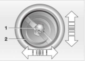
Manual adjustment The mirrors can also be adjusted manually: Press the edge of the lens.
Electric heating* Both mirrors are heated automatically when the ignition key is in position 2.
Adjusting exterior mirrors 1 Switch for choosing between the left and
right mirror
2 Switch for 4-way adjustment.
Interior rearview mirror To reduce glare from vehicles behind you when you are driving at night: Tilt the lever forward.
Illuminated vanity mirror From ignition key position 1: 1. Fold down the sun visor 2. Fold the cover panel upwards.
Sun visors Can be swung sideways.
36
MIRRORS
AIRBAGS
Interior rearview mirror, automatic dimming feature* The mirror dims automatically as required. The mirror becomes clear again when you engage reverse gear or select selector lever position R. Keep the photocells free and clean to ensure that the mirror functions perfectly. There is one photocell in the mirror frame; the other is on the back of the mirror.
Do not cover the area between the inside rearview mirror and the wind- shield, and do not place stickers or toll tags on the windshield in front of the mirror.<
1 Side airbags in seats on the driver and
passenger sides (front)
2 Head airbags on the driver and
passenger sides for both rows of seats (front/rear)
3 Front airbags on the driver and
passenger sides
Protective effect The front airbags supplement the safety belts by helping to provide additional protection for the driver and front passenger in the event of a frontal collision in which the protection afforded by the belts alone may no longer be sufficient. When needed, the head and side airbags help to furnish protection in the event of side impact. Each of the side airbags is
designed to help support the seat occu- pant’s upper body. For information on sitting posture, refer to page 31.
The airbags do not deploy in response to minor collisions, rear impacts and
certain kinds of vehicle rollover.<
Even when all safety guidelines are observed, there is a small residual risk that passengers will sustain facial, hand or arm injuries in isolated instances. The ignition and inflation noise may induce a mild temporary hearing loss in sensitive individ- uals.
Do not apply adhesive materials to the cover panels of the airbags, cover them or modify them in any other way. Do not fit covers, cushions or other items to the front seats that have not been specially approved for seats with side airbags. Do not hang clothing, e.g. jackets, over the backrests. Do not attempt to remove the airbag restraint system from the vehicle. In the event of malfunctions, immobilization or use (triggering) of the airbag restraint system in accordance with its intended function, only commission a MINI center with the inspection, repair or disassembly.
37
AIRBAGS
TRANSPORTING CHILDREN
Indicator lamp
The indicator lamp on the instru- ment panel shows the airbag system status starting from igni-
tion key position 1. System operational: > The indicator lamp comes on briefly.
System malfunction: > The indicator lamp does not come on > The indicator lamp fails to go out after
the engine has been started, or it comes on during normal driving.
A system defect could prevent the airbags from deploying in response to a severe impact occurring within the system’s normal triggering range. Have the system checked as soon as possible by your MINI center.
Do not make any changes yourself to the individual components and wiring. This includes the padded cover of the steering wheel, in the instrument panel and the roof supports, as well as the sides of the roof- liner and the original backrest covers on the front seats. Do not attempt to remove or dismantle the steering wheel. In view of the applicable safety regulations, arrange for your MINI center to dispose of the airbag generators. Unprofessional attempts to service the system could lead to failure in an emergency or undesired airbag activation, either of which could result in personal injury. Do not touch the individual components directly after the system has been triggered, as otherwise there is a danger of burns.<
At all times, occupants should sit upright and be properly restrained (infants and small children in appropriate child-restraint systems; larger children and adults using the safety belts). Never let an occupant’s head rest near or on a head airbag because the inflating airbag could cause serious or fatal injury. A child which is not properly restrained could place his or her head on or near the airbag.<
38
Children younger than 13 years and/or smaller than 5 ft (150 cm) should only travel in the rear in suitable restraint systems. Commercially-available child-restraint systems are designed to be secured with a lap belt or with the lap belt portion of a combination lap/shoulder belt. Improperly or inadequately installed restraint systems can increase the risk of injury to children. Always read and follow the instructions that come with the system. If you use a child-restraint system with a tether strap:
TRANSPORTING CHILDREN SAFELY
Both seating positions are fitted with a head restraint. Lift the head restraint and pass the tether strap between the head restraint and the seat back. It is recom- mended to readjust the head restraint into the lowest possible position.
Your vehicle has one of two different types of child-restraint anchor fittings on the back of the rear seats, see arrows 1 or 2. Depending on the location selected for seating in the rear passenger area, attach the tether strap to the corresponding anchorage point to secure the child- restraint system. Adjust the tether strap according to the child restraint manufacturer(cid:213)s instructions.
Anchor fitting 1 is shown above. Anchor fitting 2 is shown in the next
column.<
Adjust the tether strap according to the child restraint manufacturer’s instructions. Before installing any child- restraint device or child seat, please read the following: Never install a rearward-facing child- restraint system in the front passenger seat of this vehicle. Your vehicle is equipped with an airbag supplemental restraint system for the front passenger. Because the backrest on any rearward-facing child-restraint system — of the kind designed for infants under 1 year and 20 Ibs./9 kg — would be within the airbag’s deployment range, you should never mount such a device in the front passenger seat, since the impact of the airbag against the child restraint’s backrest could lead to serious or fatal injuries. If it is necessary for a child — not an infant — to ride in the front seat, certain precautions should be taken. First, move the passenger seat as far away from the instrument panel as possible. This important precaution is intended to maximize the distance between the airbag and the child. Older children should be tightly secured with a safety belt, after they have outgrown a booster seat that is appropriate for their age, height and weight. Younger children should be secured in an appropriate
39
TRANSPORTING CHILDREN SAFELY
forward-facing child-restraint system that has first been properly secured with a safety belt. Never install a rearward-facing child-restraint system in the front passenger seat. We strongly urge you to carefully read and comply with the instructions for installa- tion and use provided by the child restraint’s manufacturer whenever you use such a device. Be sure that all occupants — of all ages — remain properly and securely restrained at all times. According to accident statistics, children are safer when properly restrained in the rear seats than in the front seating posi- tions.<
All rear seats in your vehicle conform to the guidelines defined in SAE J1819, an industry recommended practice for securing child-restraint systems in motor vehicles.
Child seat security All of the rear belt retractors and the front passenger’s safety belt can be locked for mounting and securing child-restraint systems. Information regarding this is located near the buckle latch of each safety belt.
To lock the belt Pull the entire length of the belt from the belt retractor. Allow the reel to retract the belt somewhat and engage the buckle, then tighten the belt against the child- restraint system. The retraction mecha- nism is now locked.
To unlock the belt Release the buckle, remove the child- restraint system and allow the belt retractor to reel the belt completely in.
40
TRANSPORTING CHILDREN
VEHICLE MEMORY
How the system functions Doubtless you have often reflected on how great it would be if you could configure your vehicle’s various adjustment settings to meet your own personal requirements. In developing this vehicle, the manufac- turer has incorporated a number of options that your MINI center can program to reflect your individual preferences.
What the system can do Your MINI center can provide you with details on the capabilities of the Vehicle Memory system. Examples for Vehicle Memory: > Signals an acknowledgement when
locking or unlocking your vehicle
> Automatic locking after starting off > Automatic unlocking when the parking
brake is applied
> Selective central locking
First open the driver’s door, then the whole car
> Automatic opening/closing of sliding/tilt
sunroof
> Opening/closing windows and/or
sliding/tilt sunroof via remote control
> Speed-dependent windshield wiper
LATCH child-restraint system Open the cover. The illustration is an example showing the mounts for the LATCH (Lower Anchors and Tethers for Children) child-restraint mounting system at the right rear. The system is also available at the left rear position.
Always follow all manufacturer’s instructions and observe all safety precautions when installing the LATCH child-restraint system.<
> Automatic activation of windshield
wipers on cleaning
> "Follow me home" lamps
Low beams light up for a short time after the engine has been switched off
> Locking when engine is running (with
second key)
> Stop function of power windows on
opening/closing
> Activating/deactivating daytime driving
lamps*
> Switching on interior lamps via remote
control.
This symbol draws your attention to other Vehicle Memory functions
described in the Owner’s Manual.<
41
STARTING THE ENGINE
Do not allow the engine to warm up with the vehicle at a standstill. Move off imme- diately at a moderate engine speed.
Do not allow the engine to run in enclosed spaces. The exhaust gases contain carbon monoxide, an odorless and colorless, but highly toxic gas. Breathing the exhaust gases poses an extreme health risk, and can lead to uncon- sciousness and death. Do not leave the vehicle unattended with the engine running. An unattended vehicle with a running engine represents a poten- tial safety hazard. When driving, standing at idle or when parking, take precautions to avoid contact between the hot exhaust system and easily flammable materials (grass, hay or leaves, for example). Such contact could lead to a fire, resulting in serious personal injury and property damage.<
Vehicles with Continuously Variable automatic Transmission (CVT):
Do not move the selector lever from posi- tion "P" until the engine is running. Your vehicle is equipped with an interlock. Therefore, the ignition key cannot be turned to position 0 and removed until the selector lever is in position "P" (Interlock).<
1 Steering unlocked Individual electrical accessories are ready for operation. You will find that it is often easier to turn the ignition key from position 0 to posi- tion 1 when you move the steering wheel slightly to help disengage the lock.
2 Ignition switched on All electrical accessories are ready for oper- ation.
3 Starting the engine
Vehicles with manual transmission: Step on the clutch when starting the vehicle. A lockout prevents the engine from starting if the clutch is not depressed.<
IGNITION LOCK
0 Steering locked 1 Steering unlocked 2 Ignition switched on 3 Starting the engine
0 Steering locked The key can be inserted or removed in this position only.
To lock the steering: 1. Remove the key 2. Turn the steering wheel slightly to the
left or right until the lock engages.
42
STARTING THE ENGINE
SWITCHING OFF THE ENGINE
Manual transmission 1. Engage the parking brake 2. Put the manual gearshift lever in neutral 3. Press the clutch pedal 4. Start the engine.
Continuously Variable automatic Transmission (CVT)* 1. Press the footbrake 2. Put the selector lever in position P or N 3. Starting the engine.
Move the selector lever to position N and engage the parking brake before
leaving your vehicle with the engine running. Do not leave the vehicle with the engine running. An unattended vehicle with a running engine represents a potential safety hazard.<
You should never remove the ignition key when the vehicle is in motion, as
the steering lock could engage. When you leave the vehicle, always remove the ignition key and engage the steering lock. When you park on downward slopes, engage the parking brake.<
Manual transmission Turn the ignition key to position 1 or 0.
Continuously Variable automatic Transmission (CVT)* Engage selector lever position P, turn the ignition key to position 1 or 0.
Starting When starting the engine, do not press the accelerator pedal.
Do not actuate the starter for too short a time. Do not turn it for more than approx. 20 seconds. Release the igni- tion key immediately when the engine starts. Extended starting attempts, characterized by excessively frequent or long periods with the starter engaged, can lead to damage in the catalytic converter.<
If the engine does not start on the first attempt (the engine is very hot or cold, for instance): > Press the accelerator pedal halfway
down while engaging the starter.
Cold starts at extremely low temperatures (as of approx. +5 7(—15 6)): > Press the accelerator pedal halfway
down while engaging the starter
> For the initial start attempt, allow the starter to remain engaged somewhat longer (approx. 10 seconds).