- 2011 Ford Ranger Owners Manuals
- Ford Ranger Owners Manuals
- 2004 Ford Ranger Owners Manuals
- Ford Ranger Owners Manuals
- 1997 Ford Ranger Owners Manuals
- Ford Ranger Owners Manuals
- 2007 Ford Ranger Owners Manuals
- Ford Ranger Owners Manuals
- 2008 Ford Ranger Owners Manuals
- Ford Ranger Owners Manuals
- 2005 Ford Ranger Owners Manuals
- Ford Ranger Owners Manuals
- 2006 Ford Ranger Owners Manuals
- Ford Ranger Owners Manuals
- 2009 Ford Ranger Owners Manuals
- Ford Ranger Owners Manuals
- 1998 Ford Ranger Owners Manuals
- Ford Ranger Owners Manuals
- 2001 Ford Ranger Owners Manuals
- Ford Ranger Owners Manuals
- 1999 Ford Ranger Owners Manuals
- Ford Ranger Owners Manuals
- 2003 Ford Ranger Owners Manuals
- Ford Ranger Owners Manuals
- 2010 Ford Ranger Owners Manuals
- Ford Ranger Owners Manuals
- 2002 Ford Ranger Owners Manuals
- Ford Ranger Owners Manuals
- Download PDF Manual
-
%*[CF20440(R)04/96]
*[CF20442(R)03/96]
*[CF20444(R)01/96]
Controls and Features
Clock Controls on Electronic Radios The electronic radios have a built-in clock. For complete operating instructions, refer to the Audio Section in this Owner Guide.
The controls on the steering column and wheel are designed to give you easy access to the controls while you are driving. Ignition Understanding the Positions of the Ignition
The positions of the key in the ignition lock cylinder.
ACCESSORY allows some of your vehicle’s electrical accessories such as the radio and the windshield wipers to operate while the engine is not running.
In order to turn the key from the ON or OFF position to the ACCESSORY position, you must push the key release button if your vehicle’s manual transmission gearshift is mounted on the floor.
LOCK locks the steering wheel and gearshift lever.
73
File:05uncfr.ex Update:Thu Mar 20 08:51:14 1997
*[CF20450(R)01/96]
*[CF20470(R)05/96]
*[CF20480(R)01/96] *[CF20482(R)01/96] *[CF20484(R)01/96]
*[CF20486(R)01/96]
*[CF20490(R)01/96]
R WARNING
LOCK position does not lock the gearshift on floor-mounted manual transaxle gearshifts. If the parking brake is not set and the gearshift is moved out of gear, your vehicle may move unexpectedly and injure someone.
R WARNING
Do not leave the vehicle unattended with the transfer case in the N (Neutral) position. Always set the parking brake fully and turn off the ignition when leaving the vehicle.
LOCK is the only position that allows you to remove the key. The LOCK feature helps to protect your vehicle from theft.
If your key is stuck in the LOCK position and will not turn, move your steering wheel left or right until the key turns freely.
OFF allows you to shut off the engine and all accessories without locking the steering wheel or the automatic transmission gearshift lever.
ON allows you to test your vehicle’s warning lights (except the brake system warning light) to make sure they work before you start the engine. The key returns to the ON position once the engine is started and remains in this position while the engine runs.
START cranks the engine. Release the key once the engine starts so that you do not damage the starter. The key should return to ON when you release it. The START position also allows you to test the brake warning light.
74
File:05uncfr.ex Update:Thu Mar 20 08:51:14 1997
%*[CF20500(R)02/96] *[CF20600(R)02/96] *[CF20700(R)02/96] *[CF20800(R)03/96] *[CF20900(R)03/96] *[CF21000(R)03/96] %*[CF21100(R)01/96] [CF21600(R)05/96]
7-1/2 pica art:0090131-B
*[CF21800(R)08/95]
Controls and Features
The Turn Signal Lever You can use the turn signal lever on the left side of the steering column to: n operate the turn signals and cornering lamps n turn the high beams on/off n flash the lamps n turn the windshield wipers and washer on/off Turn Signals
Turn signal lever and functions
If the turn indicator light in the instrument panel does not illuminate or remains on (doesn’t flash) when you signal a turn, the turn signaling system is malfunctioning. Have this condition corrected as soon as possible, but make sure that you use the accepted hand signals in the meantime.
75
File:05uncfr.ex Update:Thu Mar 20 08:51:14 1997
*[CF23200(R)08/95] [CF23500(R)01/96]
7-1/2 pica art:0090130-A
%*[CF24400(R)01/96] *[CF24500(R)04/96]
[CF24900(R)01/96]
10-1/2 pica
art:0020084-D *[CF25000(R)08/95]
High Beams and Flashing the Lamps
Headlamp high beam switch and turn signal lever on steering column Windshield Wipers and Washer To turn on the windshield wipers, the ignition key must be turned to the ON or ACC position.
Interval wiper on turn signal lever
To set the interval wipers, rotate the knob at the end of the turn signal lever toward or away from the instrument panel to the interval operation you desire.
76
File:05uncfr.ex Update:Thu Mar 20 08:51:14 1997
[CF25200(R)01/96]
*[CF25300(R)08/95]
[CF25350(R)01/96]
*[CF25400(R)01/96]
*[CF25500(R)03/96]
Controls and Features
To clean the windshield, push in the end of the wiper knob for a single wipe. For a constant spray, keep the knob pushed in. After you release the knob, the wipers operate for two to three cycles before turning off (if wipers were off) or returning to the interval setting selected.
Do not try to clean the windshield when the washer fluid container is empty or activate the washers at any time for more than 15 seconds continuously. This could damage the washer pump system.
NOTE: The addition of shields to the front of the vehicle, as
used to deflect bugs, may also adversely affect the washer system from delivering fluid to the windshield. Devices such as bug shields are not recommended to be added to your vehicle.
R WARNING
Always warm up the windshield with the defroster before you use the washer fluid. In freezing weather, the washer solution may freeze on the windshield and obscure your vision.
For information about refilling the washer fluid or replacing your windshield wiper blades, see Windshield washer fluid and Wipers in the Index.
77
File:05uncfr.ex Update:Thu Mar 20 08:51:14 1997
[CF25502(R)01/96]
[CF25506(R)05/96]
[CF25508(R)01/96]
7-1/2 pica art:0021255-A
[CF25510(R)05/96]
[CF25512(R)05/96]
[CF25514(R)01/96]
6 pica art:0021226-B
Gearshift Lever (Automatic transmission only) The gearshift lever on your Ranger is mounted on the steering column. On the end of the gearshift lever is the transmission control switch. For additional information about the gearshift lever and the transmission control switch, see the Driving Your Ranger chapter.
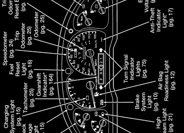
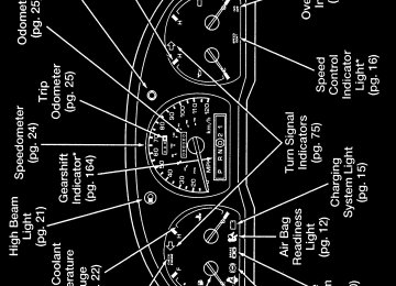
Transmission Control Indicator Light (TCIL)
The TCIL indicates the operating range of the transmission. The TCIL is located in the instrument cluster. This light illuminates when the transmission control switch is depressed. For additional information, refer to the Driving chapter.
78
File:05uncfr.ex Update:Thu Mar 20 08:51:14 1997
%*[CF26200(R)05/96] *[CF26250(R)02/96]
[CF26400(R)01/96]
7-1/2 pica art:0020088-D
[CF26450(R)04/96]
*[CF27250(R)01/96]
%*[CF27300(R)03/96] *[CF27400(R)05/96] *[CF27450(R)05/96]
Controls and Features
Tilt Steering (If equipped)
R WARNING
Never adjust the steering wheel when the vehicle is moving.
Tilt steering wheel lever
To change the position of the steering wheel, push the release lever under the steering column away from you. Tip the steering wheel to the desired position. Pull the lever back into place to lock the steering wheel.
Be sure the steering wheel locks in a notch. It is not infinitely adjustable. Do not adjust the steering wheel while the vehicle is in motion. Speed Control (If equipped) The speed of the vehicle cannot be automatically controlled until the vehicle speed is at or above 30 mph (48 km/h).
Use of radio transmitting equipment that is not Federal Communications Commission (FCC) or in Canada the Canadian Radio and Telecommunications Commission (CRTC) approved may cause the speed control to malfunction. Therefore, use only properly installed FCC (CRTC in Canada) approved radio transmitting equipment in your vehicle.
79
File:05uncfr.ex Update:Thu Mar 20 08:51:14 1997
[CF27500(R)01/96]
7-1/2 pica art:0020091-F
%*[CF27800(R)05/96] *[CF27820(R)05/96] *[CF27840(R)05/96] *[CF27860(R)05/96] *[CF27880(R)05/96] *[CF27900(R)05/96] *[CF27920(R)05/96] [CF27940(R)05/96]
*[CF27960(R)05/96] *[CF27980(R)05/96]
The speed control switches To Turn Speed Control Off n Press OFF, n Turn off the vehicle ignition.
Once speed control is switched off, the previously programmed set speed will be erased. To Turn Speed Control On n Press ON To Set a Speed
Press SET ACCEL. For speed control to operate, the speed control must be ON and the vehicle speed must be greater than 30 mph (48 km/h). The SPEED CONT light will illuminate in the instrument cluster when a speed is set/engaged.
If you drive up or down a steep hill, your vehicle speed may vary slower or faster than the set speed. This is normal.
Speed control cannot reduce the vehicle speed if it increases above the set speed on a downhill. If your vehicle speed is faster than the set speed while driving downhill in j (Overdrive), you may want to shift to the next lower gear to reduce your vehicle’s speed.
80
File:05uncfr.ex Update:Thu Mar 20 08:51:14 1997
*[CF28000(R)05/96]
*[CF28020(R)05/96] [CF28040(R)05/96]
[CF28060(R)05/96]
*[CF28080(R)05/96] *[CF28100(R)05/96]
*[CF28120(R)05/96] [CF28140(R)05/96]
[CF28160(R)05/96]
*[CF28180(R)05/96]
Controls and Features
R WARNING
To keep your vehicle under control, do not use speed control in heavy traffic or on roads that are winding, slippery, or unpaved.
To Set a Higher Speed n Press and hold SET ACCEL. Release the switch when the
desired vehicle speed is reached, or
n Press and release SET ACCEL. Each press will increase the
set speed by 1 mph (1.6 km/h)or
n Accelerate with your accelerator pedal, then press SET
ACCEL.
You may accelerate with the accelerator pedal at any time during speed control usage. Releasing the accelerator pedal will return your vehicle speed to the previously programmed set speed. To Set a Lower Set Speed n Press and hold COAST. Release the switch when the desired
vehicle speed is reached, or
n Press and release COAST. Each press will decrease the set
speed by 1 mph (1.6 km/h) or
n Depress the brake pedal. When the desired vehicle speed is
reached, press SET ACCEL.
81
File:05uncfr.ex Update:Thu Mar 20 08:51:14 1997
*[CF28200(R)05/96] [CF28220(R)05/96]
[CF28240(R)05/96]
[CF28260(R)05/96]
*[CF28280(R)05/96] [CF28300(R)05/96]
%*[CF36000(R)02/96] %*[CF38200(R)01/96] [CF38300(R)01/96]
7-1/2 pica art:0020192-D
*[CF38400(R)01/96]
*[CF38500(R)01/96] *[CF38600(R)01/96]
To Disengage Speed Control n Depress the brake pedal, or n Depress the clutch pedal (if equipped). Disengaging the speed control will not erase the previously set speed and the SPEED CONT light will turn off. To Return to a Set Speed n Press RSM. For RSM to operate, the vehicle speed must be
faster than 30 mph (48 km/h).
Doors Tailgate
Tailgate operation When open, the tailgate load should not exceed 500 lbs (227 kgs). If you want to load heavy items onto your vehicle, Ford recommends that you load them one at a time, directly on the bed floor to avoid damage to the tailgate or its supports. To release the tailgate: Open the tailgate as directed above, but support it to allow for slack in the cables at both sides. Use a coin or similar object to pry the spring clip (on each upper cable connector) past the head of the support screw. Doing so will allow you to center the wider opening in the connector over the screw head and disconnect it.
82
File:05uncfr.ex Update:Thu Mar 20 08:51:14 1997
*[CF38700(R)01/96] *[CF38800(R)01/96]
[CF38900(R)01/96]
7-1/2 pica art:0020194-C
*[CF38950(R)01/96] *[CF39000(R)01/96]
[CF39100(R)01/96]
10-1/2 pica
Controls and Features
If you disconnect the upper end of each cable, you can lower the tailgate completely.
NOTE: Step bumpers or hitches may damage the tailgate if it
is lowered completely.
Releasing the tailgate
Tailgate removal
First release the tailgate as described above. Be sure to support the left side to prevent it from falling. Then raise the tailgate to a 45 degree angle (see the following illustration) and lift the right side of the tailgate off its hinge. You can now pull the left side of the tailgate away from the left hinge.
art:0020196-C
Tailgate removal
83
File:05uncfr.ex Update:Thu Mar 20 08:51:14 1997
*[CF39200(R)01/96]
%*[CF39300(R)01/96] [CF39500(R)05/96]
*[CF39600(R)01/96]
[CF39700(R)01/96]
7-1/2 pica art:0020204-F
%*[CF46500(R)04/96] %*[CF47800(R)01/96] [CF47900(R)01/96]
*[CF48300(R)01/96]
R WARNING
Do not drive your vehicle with the tailgate open unless there is a load holding it in place.
Power Door Locks (If equipped)
The power door lock switches are located in the front doors. To lock all doors push the switch marked L. To unlock all doors push the switch marked U.
The manual door locks will override the power door lock controls.
Power door lock controls Windows Using the Power Windows (If equipped)
Each door has a power control that opens and closes the window on that door. The driver’s door has a master control switch that operates all door windows. You must place the ignition switch in the ON or ACC position to use your power window controls.
Do not let children play with the power windows.
R WARNING
84
File:05uncfr.ex Update:Thu Mar 20 08:51:14 1997
[CF48400(R)01/96]
10-1/2 pica
art:0020211-H
[CF48410(R)05/96]
[CF48420(R)05/96]
[CF48430(R)05/96]
10-1/2 pica
Controls and Features
Master control switch
Sliding rear window (If equipped)
The sliding rear window has only one sliding portion. Follow the operating instructions shown in the following illustration.
art:0020210-B
Sliding rear window operation
85
File:05uncfr.ex Update:Thu Mar 20 08:51:14 1997
[CF48450(R)05/96]
[CF48460(R)05/96]
[CF48470(R)05/96]
10-1/2 pica
art:0020209-B %*[CF48700(R)05/96] *[CF48800(R)05/96] *[CF48900(R)05/96] [CF48910(R)01/96]
SuperCab quarter windows (if equipped)
To open the optional flip quarter windows on the Ranger SuperCab models, follow the operating instructions shown in the following illustration.
SuperCab flip open quarter window
Dual Electric Remote Control Mirrors (If equipped)
To adjust the remote controlled side mirrors:
1. Find the control switch in the driver’s door panel.
2. Select the right or left mirror by moving the selector switch
to the right or left.
86
File:05uncfr.ex Update:Thu Mar 20 08:51:14 1997
*[CF48920(R)05/96] *[CF48930(R)05/96]
[CF49000(R)01/96]
7-1/2 pica art:0090159-A
*[CF49100(R)05/96] *[CF49200(R)05/96]
Controls and Features
3. Move the control knob in the direction you want to move
the mirror.
4. Return the selector switch to the middle position to keep the
mirror in place.
Power mirror control
Do not clean the plastic housing of any electric mirror with gasoline or other petroleum-based cleaning products.
R WARNING
The right side view mirror makes objects appear smaller and farther away than they actually are.
87
File:05uncfr.ex Update:Thu Mar 20 08:51:14 1997
[CF50000(R)01/96] *[CF50100(R)01/96]
[CF59700(R)01/96]
17-1/2 pica
Console (If equipped) Your vehicle may have a full console. The full console has the features shown in the illustration below.
art:0090211-A
The features on the console — bucket seats
88
File:05uncfr.ex Update:Thu Mar 20 08:51:14 1997
[CF59800(R)01/96]
17-1/2 pica
art:0020896-C
[CF66700(R)01/96]
[CF66900(R)03/96]
[CF67000(R)01/96]
Controls and Features
Storage armrest — 60/40 split bench Floor Mounted Cupholders (If equipped) If your vehicle has a bench seat, you may have floor mounted cupholders. On manual transmission vehicles, the cupholders are located on the floor on either side of the gearshift lever. On automatic transmission vehicles, a removable consolette is located on the floor. The consolette may be removed when the center bench seat position is occupied.
The inside of the cupholders can be adjusted to various heights to accommodate different size cups. They can also be removed to allow access and cleaning of the rubber padding at the bottom of the cupholder.
89
File:05uncfr.ex Update:Thu Mar 20 08:51:14 1997
[CF67200(R)05/96]
10-1/2 pica art:0020897-E
[CF67300(R)01/96]
Floor mounted cupholders — manual transmission
17-1/2 pica
art:0020962-B
Floor mounted cupholders — automatic transmission
90
File:05uncfr.ex Update:Thu Mar 20 08:51:14 1997
[CF67400(R)01/96]
[CF67500(R)01/96]
[CF67600(R)01/96]
[CF67700(R)01/96]
[CF67800(R)01/96]
[CF67900(R)05/96]
[CF67910(R)05/96]
[CF67912(R)06/96]
[CF67915(R)05/96]
[CF67920(R)01/96]
Controls and Features
To remove the automatic transmission consolette:
1. Pull the adjustable portion of each cupholder from the
consolette.
2. Remove the rubber pad at the bottom of each cupholder.
3. Using a quarter, turn the slotted head at the bottom of each
cupholder 90˚ (one quarter turn).
4. Lift the consolette from the floor and secure it in a safe
place.
Power Point Electrical Outlets The two power point outlets should be used in place of the cigarette lighter for optional electrical accessories.
The instrument panel power point is located to the right of the radio.
Vehicles equipped with the Passenger Air Bag Deactivate switch do not come equipped with an auxiliary power point to the left of the ashtray.
NOTE: Do not plug optional electrical accessories into the
cigarette lighter. Use the power point.
91
File:05uncfr.ex Update:Thu Mar 20 08:51:14 1997
[CF67925(R)05/96]
13-1/2 pica
art:0090227-A
[CF67930(R)01/96]
7-1/2 pica art:0020260-E
The Instrument panel power point
Power point electrical outlet
92
File:05uncfr.ex Update:Thu Mar 20 08:51:14 1997
*[CF80000(R)05/96] [CF80010(R)01/96]
[CF80016(R)01/96]
*[CF80018(R)01/96]
Controls and Features
Remote Entry System (If equipped) If your vehicle has the remote entry system, you can lock or unlock the vehicle doors without using a key. The remote also has a personal alarm feature. The buttons for the system are located on the hand held transmitter that came with your vehicle.
The system will work with up to four transmitters. Your vehicle came with one transmitter. Additional transmitters can be ordered from your dealer.
The remote entry features only operate with the ignition in the OFF position.
93
File:05uncfr.ex Update:Thu Mar 20 08:51:14 1997
[CF80020(R)05/96]
7-1/2 pica art:0090226-A
%*[CF80080(R)05/96] *[CF80082(R)04/96] [CF80086(R)05/96]
*[CF80100(R)05/96] [CF80110(R)05/96]
[CF80114(R)05/96]
%*[CF80200(R)05/96] [CF80210(R)05/96]
The remote entry transmitter
Unlocking the doors with the remote entry system
To unlock the driver’s door, press the UNLOCK control.
To unlock the other door, press the UNLOCK control a second time, within five seconds after the first UNLOCK.
Locking the doors with the remote entry system
To lock both doors, press the LOCK control. This will also arm the factory installed Anti-Theft system.
If you would like a signal that the doors are being locked, press the LOCK control again within five seconds. If all doors are completely closed, the doors will lock again, the horn will chirp, and the parking lamps will flash. If a door is open or ajar, the horn will give two short chirps warning you that a door is open.
Remote entry personal alarm
If you wish to activate the remote entry system personal alarm, press the PANIC control. This will honk the horn and flash the lights for approximately 2 minutes 45 seconds. You can turn it off by pressing the PANIC control again from the transmitter or by turning the ignition to the ON or ACCESSORY position.
94
File:05uncfr.ex Update:Thu Mar 20 08:51:14 1997
*[CF80212(R)05/96]
[CF80214(R)01/96]
7-1/2 pica art:0021160-A
% [CF80300(R)04/96]
[CF80310(R)05/96]
*[CF80320(R)01/96] %*[CF80500(R)05/96] *[CF80510(R)05/96]
Controls and Features
When you use the remote entry UNLOCK or PANIC controls, the illuminated entry system turns on the vehicle’s interior lights for 25 seconds. You can turn these lights off with the remote entry LOCK control or by turning the ignition to the ON or ACCESSORY position.
Arming and Disarming the Alarm System with Remote Entry
Your Remote Entry System will automatically arm the factory installed Anti-Theft System when the doors are locked, and automatically disarm it when the doors are unlocked. The remote will also reset the anti-theft alarm (when the driver’s door is unlocked or the PANIC control is pressed on a programmed remote entry transmitter) if it was triggered.
The remote entry system may not arm and disarm non-factory installed anti-theft systems. Replacing the Batteries
The remote is powered by two coin type three-volt lithium 2016
batteries (included) that should last for several years of normal use. If you notice a significant decrease in operating range, the batteries should be replaced. Replacement batteries can be purchased at most pharmacies, watch stores or at your Ford or Lincoln-Mercury dealer.95
File:05uncfr.ex Update:Thu Mar 20 08:51:14 1997
*[CF80520(R)01/96]
[CF80530(R)01/96]
7-1/2 pica art:0021161-A
*[CF80540(R)05/96]
[CF80550(R)01/96]
7-1/2 pica art:0021162-A
NOTE: The operating range of the remote entry system can also be affected by weather conditions (such as very cold temperatures) or structures around the vehicle (buildings, other vehicles, radio and TV towers, etc.). Typical operating range will allow you to be up to 33
feet (10 meters) away from your vehicle.Opening the remote transmitter
The remote can be snapped apart to replace the batteries by twisting a thin coin between the two halves of the remote. DO NOT TAKE THE FRONT PART OF THE REMOTE APART. When installing the new batteries, be sure to place the positive (+) side down as marked. Snap the two halves back together.
Replacing the batteries
96
File:05uncfr.ex Update:Thu Mar 20 08:51:14 1997
%*[CF80560(R)05/96] [CF80562(R)01/96]
*[CF80564(R)01/96]
%*[CF80570(R)01/96] *[CF80574(R)01/96]
[CF80578(R)04/96]
%*[CF80600(R)01/96] [CF80610(R)04/96]
*[CF80630(R)01/96]
Controls and Features
Replacing lost transmitters
In the event a transmitter is lost, you should take your vehicle’s transmitters to your dealer to have the remote entry system deprogrammed for the lost transmitter. This is necessary to prevent further unauthorized use of the lost transmitter.
You can also purchase additional transmitters (up to 4
transmitters can be used) from your dealer. You will need to take all your transmitters to the dealer so they can program them to the remote entry system all at the same time. Illuminated Entry System (If equipped)This system will provide illumination of the vehicle’s interior courtesy lamps when either outside front door handle is pulled or when the remote entry system is used to unlock the door or sound the personal alarm. The system will automatically turn off after approximately 25 seconds or when the ignition is turned to the RUN or ACC position.
NOTE: The inside lights will not turn off if you have turned them on with the dimmer thumbwheel or if any door is open.
Battery Saver When the ignition is turned off, the vehicle will turn off battery voltage to all of these lights after 40 minutes: glove box, engine compartment, overhead console, mirror, courtesy and interior (including cargo) lamps.
This will prevent draining of the battery if these lights have been left on inadvertently or if a door is not completely closed. Battery voltage to these lamps will be restored when the remote entry transmitter is used, any door is opened, or the ignition key is turned on again.
97
File:05uncfr.ex Update:Thu Mar 20 08:51:14 1997
%*[CF81000(R)03/96] *[CF81100(R)01/96] %*[CF81110(R)01/96] [CF81122(R)01/96] *[CF81124(R)01/96] *[CF81126(R)01/96] %*[CF81200(R)01/96] [CF81210(R)04/96]
[CF81212(R)05/96]
[CF81216(R)05/96]
[CF81250(R)01/96]
[CF81264(R)01/96]
[CF81300(R)01/96]
Anti-Theft Alarm System (If equipped) When armed, this system helps protect your vehicle against break-ins or theft. When an unauthorized entry occurs, the system triggers and will: n flash the parking lamps and theft indicator lamp n honk the horn n disable the starting circuit to prevent the vehicle from being
started
Arming the System The system is ready to arm any time the ignition switch is turned OFF and the alarm is not triggered or sounding. Any of the following events will prearm the anti-theft system: n Pressing the remote entry transmitter LOCK control to lock
the doors (with the doors open or closed),
n Opening a door and pressing the power door lock control to
lock the doors.
If a door is open, the anti-theft system is prearmed and waiting for all doors to close. The THEFT indicator in the instrument panel will light continuously while the system is prearmed. n Close all doors Once all doors are closed, if any were open, the system will begin a 30 second countdown to become armed. The 30 second countdown allows people who may still be in the vehicle time to exit without triggering the alarm. The THEFT indicator will glow steadily until the system is armed. When the system is armed, the THEFT indicator will begin to flash with short flashes every 2 seconds until the system is triggered or disarmed.
98
File:05uncfr.ex Update:Thu Mar 20 08:51:14 1997
[CF81340(R)01/96]
[CF81360(R)05/96]
% [CF81400(R)01/96]
[CF81410(R)04/96]
[CF81420(R)05/96]
[CF81435(R)01/96]
[CF81439(R)04/96]
[CF81440(R)04/96]
[CF81442(R)04/96]
*[CF81448(R)01/96]
*[CF81450(R)01/96]
Controls and Features
Remember, all doors must be fully closed for the anti-theft system to arm. If a door has been left open or ajar, and you press the remote entry transmitter twice to confirm the doors are locked, two short horn chirps will warn you that the anti-theft system is not arming. When you get a single horn chirp by pressing the LOCK control twice within 5 seconds on your remote entry transmitter, you can be assured that all doors are locked and the anti-theft system is arming. Disarming the System An armed or activated system can be disarmed if you: n Unlock the doors by pressing the remote entry transmitter
UNLOCK control.
n Unlock any door with a key. n Turn ignition to the ON or ACC position. n Pressing the remote entry PANIC button will disarm the
anti-theft system only when the anti-theft alarm is triggered and sounding.
When unlocking the vehicle with a key, turn the key all the way to the end of its travel or the system may not disarm. NOTE: The flashing lights and honking horn will shut off automatically within 2 minutes 45 seconds after the system is triggered. It will trigger again if another intrusion occurs. However, the starter circuit remains disabled until the system is disarmed.
The anti-theft system is designed to work with the factory installed remote entry system. It may not work with other remote entry systems.
99
File:06unssr.ex Update:Fri Mar 21 09:43:41 1997
%*[SS00125(R)05/96] %*[SS00200(R)01/96] [SS00210(R)01/96] *[SS00220(R)01/96] *[SS00222(R)01/96] *[SS00224(R)01/96] *[SS00226(R)01/96] [SS00228(R)01/96]
[SS00240(R)01/96]
10-1/2 pica
Seating and Safety Restraints
Seats Adjusting the Front Seat Manually
Regular Cab
To move the front seat forward or rearward:
1. Find the adjustment lever at the lower left corner of the
front seat.
2. Push the lever to the left to unlock the seat.
3. Move the seat to the desired position.
4. Release the lever to lock the seat in its new position. Make
sure the seat locks securely in place.
art:0020859-C
Adjusting the bench seat
101
File:06unssr.ex Update:Fri Mar 21 09:43:41 1997
[SS00250(R)01/96]
10-1/2 pica
art:0020911-C
[SS00260(R)01/96] *[SS00262(R)01/96] [SS00264(R)01/96]
[SS00266(R)01/96] *[SS00268(R)01/96] [SS00270(R)01/96]
Adjusting the bucket seat
SuperCab To move the front seat forward or rearward: 1. Find the adjustment bar at lower front of the front seat. 2. Lift bar upward to unlatch the seat. 3. Move the seat to the desired position. 4. Release the bar to latch the seat in its new position. Make
sure the seat latches securely in place.
102
File:06unssr.ex Update:Fri Mar 21 09:43:41 1997
[SS00280(R)01/96]
13-1/2 pica
art:0021273-A *[SS00290(R)05/96]
*[SS00300(R)05/96]
*[SS00310(R)02/96]
*[SS00320(R)02/96]
Seating and Safety Restraints
Adjusting the bucket seat
R WARNING
Never adjust the driver’s seat or seatback when the vehicle is moving.
R WARNING
Cargo should always be secured to prevent it from shifting and causing damage to the vehicle or harm to passengers.
R WARNING
Always drive and ride with your seatback upright and the lap belt snug and low across the hips.
R WARNING
Children should always ride with the seatback in the fully upright position.
103
File:06unssr.ex Update:Fri Mar 21 09:43:41 1997
[SS00330(R)01/96]
[SS00332(R)01/96]
*[SS00334(R)01/96] *[SS00336(R)01/96] *[SS00338(R)01/96] *[SS00340(R)01/96] *[SS00342(R)01/96]
[SS00354(R)01/96]
[SS00356(R)01/96]
10-1/2 pica
Reclining Bucket Seats (If equipped)
If your vehicle is equipped with the optional reclining bucket seat, you can tilt the seatback up to 30 degrees rearward.
1. On the side of the seat, find the handle for the recliner.
2. Lift the handle up and hold it in place.
3. Lean against the back of the seat and adjust it to the position
you want.
4. Release the handle to lock the seatback in position.
5. To return the seatback to upright position, lift the handle
and lean forward. Then release the handle.
Lifting the recliner handle of an unoccupied seat will allow the seat back to fold forward for access to the rear. Pushing the seat back with the release handle raised returns the seat back to the upright position.
art:0021165-A
Reclining bucket seat
104
File:06unssr.ex Update:Fri Mar 21 09:43:41 1997
*[SS00549(R)01/96] [SS00551(R)01/96]
[SS00560(R)01/96]
10-1/2 pica
art:0020232-B *[SS00570(R)01/96]
[SS00580(R)01/96]
[SS00590(R)01/96]
[SS00610(R)01/96]
*[SS00620(R)01/96] [SS00622(R)01/96]
*[SS00624(R)01/96]
Seating and Safety Restraints
Center Facing Jump Seat — SuperCab Only To open the seat, pull inboard and down on the seat handle. To stow the seat, pull seat bottom back to the fully upright position. The jump seats should be kept in the stored position for easier access to the rear cab area.
Center facing jump seat in stowed position
R WARNING
Do not install a child seat in a center facing jump seat.
Tilt Slide Seat (If equipped) SuperCab only With the front seatback tilted forward, the tilt slide seat can be moved to provide additional entry space to access the rear seat compartment of the vehicle. To operate the tilt slide seat: 1. Lift the seatback release lever on the outboard side of the seat cushion to unlock the slide mechanism and seatback.
2. Push the seat assembly forward to provide entry space to the
rear seat compartment of the vehicle.
105
File:06unssr.ex Update:Fri Mar 21 09:43:41 1997
*[SS00630(R)02/96]
*[SS00640(R)02/96]
[SS00650(R)01/96]
[SS00652(R)01/96]
*[SS00654(R)01/96]
R WARNING
Check to see that the seat and seatback are latched securely in position. Keep floor area free of objects that would prevent proper seat engagement. Never attempt to adjust the seat while the vehicle is in motion.
R WARNING
Check to see that the seat and seatback are latched securely in position. Keep floor area free of objects that would prevent proper seat engagement. Never attempt to adjust the seat while the vehicle is in motion.
3. With the seatback still forward, using the seat cushion push
the seat rearward to the desired position and return the seatback to its upright position. This will lock the seat track.
NOTE: Whenever the seatback is returned to the upright
position, the seat will lock in that seat position.
NOTE: The seat can no longer be moved rearward when in
its latched position.
106
File:06unssr.ex Update:Fri Mar 21 09:43:41 1997
[SS00656(R)01/96]
10-1/2 pica
art:0021166-A *[SS00670(R)01/96]
[SS00675(R)01/96]
10-1/2 pica
Seating and Safety Restraints
Tilt slide seat
Prior to operating the vehicle, check to ensure that the seat assembly is locked by pushing or pulling the seat forward or rearward. If seat does not lock, repeat steps 2 and 3.
art:0021167-B
Locking tilt slide seat
107
File:06unssr.ex Update:Fri Mar 21 09:43:41 1997
*[SS00680(R)01/96] [SS00681(R)01/96]
[SS00690(R)01/96]
10-1/2 pica
art:0021168-B
[SS00700(R)01/96]
[SS00704(R)01/96]
[SS00720(R)01/96]
7-1/2 pica art:0020241-D
To operate the seat adjuster:
4. To adjust the seats forward or rearward, locate the release
bar at the lower front area of the seat cushion. Lift the release bar and hold until the desired seat position is obtained, then release the bar to relock the seat.
Adjusting seat
60/40 Split Front Bench (If equipped)
The seat back release operates the same as the basic bucket seat.
60/40 split front bench
108
File:06unssr.ex Update:Fri Mar 21 09:43:41 1997
%*[SS00740(R)01/96] *[SS00742(R)01/96]
[SS00750(R)05/96]
17-1/2 pica
art:0020888-C
[SS00810(R)05/96]
[SS00812(R)05/96]
[SS00816(R)01/96]
Seating and Safety Restraints
Using the Power Seats (If equipped)
If your vehicle has the power seat option, you can adjust it in several directions. The controls are on the outboard side of the seat.
The power controls on the driver’s seat
Inflating the lumbar support
If your vehicle is equipped with this option you can inflate/deflate the lumbar support pad in the seat back.
To inflate the lumbar support pad, push the “+” end of the rear rocker switch. To deflate the lumbar support pad, push the “Ҁ” end of the switch.
109
File:06unssr.ex Update:Fri Mar 21 09:43:41 1997
[SS00830(R)05/96]
16 pica
art:0021169-D
%*[SS00900(R)02/96] *[SS00910(R)05/96]
*[SS00920(R)02/96] *[SS00930(R)02/96] *[SS00950(R)02/96] *[SS01000(R)02/96] *[SS01100(R)02/96] *[SS01200(R)02/96] *[SS02050(R)02/96]
Power lumbar switch — sport bucket seat Important Safety Belt Information The use of safety belts helps to restrain you and your passengers in case of a collision. In most states and in Canada, the law requires their use. Safety belts provide best restraint when: n the seatback is upright n the occupant is sitting upright (not slouched) n the lap belt is snug and low on the hips n the shoulder belt is snug against the chest n the knees are straight forward To help you remember to fasten your safety belt, a warning light may come on and a chime may sound. See Safety Belt Warning Light and Chime in the Instrumentation chapter.
110
File:06unssr.ex Update:Fri Mar 21 09:43:41 1997
*[SS02100(R)02/96]
*[SS02200(R)02/96]
*[SS02500(R)02/96]
*[SS02550(R)02/96]
*[SS02600(R)02/96]
Seating and Safety Restraints
See the following sections in this chapter for directions on how to properly use these safety belts. Also see Safety Restraints for Children in this chapter for special instructions about using safety belts for children.
R WARNING
Always drive and ride with your seatback upright and the lap belt snug and low across the hips.
R WARNING
Never let a passenger hold a child on his or her lap while the vehicle is moving. The passenger cannot protect the child from injury in a collision.
R WARNING
Ford recommends that all safety belt assemblies and attaching hardware should be inspected by a qualified technician after any collision. Safety belt assemblies not in use during a collision should also be inspected and replaced if either damage or improper operation is noted.
R WARNING
Children should always ride with the seatback in the fully upright position.
111
File:06unssr.ex Update:Fri Mar 21 09:43:41 1997
*[SS02800(R)05/96]
*[SS02900(R)02/96]
*[SS02950(R)05/96]
%*[SS03000(R)02/96] *[SS03200(R)02/96]
*[SS03400(R)01/96] *[SS03500(R)02/96]
R WARNING
Each seating position in your vehicle has a specific safety belt assembly which is made up of one buckle and one tongue that are designed to be used as a pair. 1) Use the shoulder belt on the outside shoulder only. Never wear the shoulder belt under the arm. 2) Never swing it around your neck over the inside shoulder. 3) Never use a single belt for more than one person.
R WARNING
Lock the doors of your vehicle before driving to lessen the risk of the door coming open in a collision.
R WARNING
It is extremely dangerous to ride in a cargo area, inside or outside of a vehicle. In a collision, people riding in these areas are more likely to be seriously injured or killed. Do not allow people to ride in any area of your vehicle that is not equipped with seats and safety belts. Be sure everyone in your vehicle is in a seat and using a safety belt properly.
Combination Lap and Shoulder Belts While your vehicle is in motion, the combination lap and shoulder belt adjusts to your movement. However, if you brake hard, turn hard, or if your vehicle receives an impact of 5 mph (8 km/h) or more, the lap/shoulder belt locks and helps reduce your forward movement. After you get into your vehicle, close the door and lock it. Then adjust the seat to the position that suits you best. Pull the combination lap/shoulder belt from the retractor so that the shoulder portion of the belt crosses your shoulder and
112
File:06unssr.ex Update:Fri Mar 21 09:43:41 1997
[SS03510(R)02/96]
one third page
art:0001196-A *[SS03511(R)02/96]
[SS03512(R)01/96]
10-1/2 pica
art:0021301-A
Seating and Safety Restraints
chest. Be sure the belt is not twisted. If it is, remove the twist. Insert the belt tongue into the proper buckle until you hear a snap and feel it latch. Make sure the tongue is securely fastened to the buckle by pulling on tongue.
Fastening the outboard lap/shoulder belts
NOTE: Be sure to read and understand Important Safety Belt
Information in this chapter.
Unfastening the outboard lap/shoulder belts
113
File:06unssr.ex Update:Fri Mar 21 09:43:41 1997
*[SS03513(R)02/96] *[SS03514(R)01/96] *[SS03516(R)01/96]
*[SS03518(R)02/96] *[SS03519(R)02/96] *[SS03520(R)02/96]
%*[SS03521(R)02/96] *[SS03522(R)01/96]
*[SS03523(R)01/96] *[SS03524(R)01/96] *[SS03525(R)01/96]
While the belt retracts, guide the tongue to its original position to prevent it from striking you or the vehicle. Safety Belts for Front Outboard Passenger and Rear Outboard Seating Positions
Your vehicle is equipped with a dual locking mode retractor on the shoulder belt portion of the combination lap/shoulder safety belt for the front seat outboard passenger and rear outboard passengers.
Dual locking mode retractors operate in two ways:
Vehicle sensitive (emergency) locking mode
In this operating mode, the shoulder belt retractor will allow the occupant freedom of movement, locking tight only on hard braking, hard cornering or impacts of approximately 5 mph (8 km/h) or more. The retractor can also be made to lock by pulling the belt out quickly.
Automatic locking mode
In this operating mode, the shoulder belt retractor will be automatically locked and will remain locked when the combination lap/shoulder safety belt is buckled, and does not allow the occupant freedom of movement. This mode provides the following: n A tight lap/shoulder belt on the occupant. n Child safety seat installation.
This mode must be used when installing a child safety seat on the front passenger seat and rear outboard seats where dual locking retractors are provided.
114
File:06unssr.ex Update:Fri Mar 21 09:43:41 1997
*[SS03529(R)01/96] *[SS03530(R)02/96] *[SS03531(R)01/96]
*[SS03532(R)02/96]
*[SS03533(R)02/96]
%*[SS03534(R)01/96] *[SS03535(R)05/96] [SS03536(R)01/96]
*[SS03537(R)05/96]
Seating and Safety Restraints
To switch the retractor from the emergency locking mode to the automatic locking mode, perform the following steps:
1. Buckle the lap/shoulder combination belt.
2. Grasp the shoulder portion of the belt and pull downward
until all of the belt is extracted and, when allowed to retract, a clicking sound is heard. At this time, the belt retractor is in the automatic locking mode (child restraint mode).
3. A clicking sound will continue to be heard as the belt is
allowed to retract. This indicates that the retractor is in the automatic locking mode.
NOTE: When the combination lap/shoulder belt is unbuckled
and allowed to retract completely, the retractor will switch to the vehicle sensitive (emergency) locking mode. See the detailed instructions under Safety Seats for Children in this chapter.
Shoulder Belt Height Adjustment
Driver and right front passenger
The driver and right front passenger shoulder belt height is adjustable to one of four (4) positions (Regular cab model) or five (5) positions (Super cab model).
To adjust the belt down, push the release button on the adjuster down and slide the adjuster down. Then release the button and make sure the adjuster is firmly in one of the positions. To adjust the belt up, slide the adjuster up. (You do not have to push the release button.) Slide it up or down until the belt rests across the middle of your shoulder.
115
File:06unssr.ex Update:Fri Mar 21 09:43:41 1997
*[SS03540(R)05/96]
*[SS03550(R)05/96]
[SS03552(R)01/96]
17-1/2 pica
R WARNING
Position the shoulder belt height adjuster so that the belt rests across the middle of your shoulder. Be sure the shoulder belt is properly positioned on your shoulder each time you use the belt. If the shoulder belt is off your shoulder, on your upper arm or neck, there is a greater risk of severe injury in a collision.
NOTE: Be sure the belt is properly positioned on your
shoulder each time you use the belt.
art:0090166-B
Shoulder belt height adjuster — full up position (regular cab models)
116
File:06unssr.ex Update:Fri Mar 21 09:43:41 1997
[SS03558(R)01/96]
17-1/2 pica
art:0021279-B *[SS03600(R)05/96]
*[SS03700(R)01/96]
Seating and Safety Restraints
Shoulder belt height adjuster — full up position (SuperCab models)
R WARNING
Each seating position in your vehicle has a specific safety belt assembly which is made up of one buckle and one tongue that are designed to be used as a pair. 1) Use the shoulder belt on the outside shoulder only. Never wear the shoulder belt under the arm. 2) Never swing it around your neck over the inside shoulder. 3) Never use a single belt for more than one person.
To tighten the lap portion of the belt, pull up on the shoulder belt until it fits you snugly. The belt should rest as low on your hips as possible.
117
File:06unssr.ex Update:Fri Mar 21 09:43:41 1997
[SS03800(R)01/96]
10-1/2 pica
art:0021301-A
[SS05800(R)01/96]
[SS05900(R)01/96]
*[SS05950(R)01/96]
%*[SS06100(R)01/96]
*[SS06400(R)01/96]
[SS06500(R)01/96]
[SS06600(R)01/96]
Unfastening the outboard lap/shoulder belts
Center Front Lap Belt (If equipped)
The lap belt in the center of the front seat does not adjust automatically. You must adjust it to fit snugly around your hips. Do not wear it around your waist.
To fasten the belt, pull the belt across your hips and insert the tongue into the correct buckle on your seat until you hear a snap and feel it lock. Make sure the buckle is securely fastened.
If you need to lengthen the belt, unfasten it and tip the belt tongue at a right angle to the belt. Pull the belt tongue over your lap until it reaches the buckle.
If you need to shorten the belt, pull on the loose end of the webbing until the belt fits snugly.
To unfasten the belt, push the release button on the buckle. This allows the tongue to unlatch from the buckle.
Because the center front lap belt does not have a retractor, it should be shortened and fastened when not in use.
118
File:06unssr.ex Update:Fri Mar 21 09:43:41 1997
[SS06700(R)01/96]
10-1/2 pica
art:0021123-A *[SS06800(R)05/96]
[SS07900(R)01/96]
[SS08000(R)01/96]
[SS08500(R)04/96] *[SS08600(R)08/95] *[SS08700(R)01/96]
Seating and Safety Restraints
Fastening and unfastening the front center safety belt
R WARNING
The lap belts should fit snugly and as low as possible around the hips, not around the waist.
Rear Lap Belt with Retractor
Pull the belt out of the retractor with a steady motion and insert the tongue into the proper buckle until you hear a snap and feel the latch engage. To Unfasten the Safety Belts with Retractors:
1. Push the release button on the buckle. This allows the
tongue to unlatch from the buckle.
2. While the belt retracts, guide the tongue to its stowed
position. If you do not guide the tongue, it may strike you or part of the vehicle.
119
File:06unssr.ex Update:Fri Mar 21 09:43:41 1997
%*[SS09600(R)02/96] *[SS09700(R)01/96]
*[SS09790(R)01/96]
*[SS09800(R)02/96]
%*[SS09900(R)03/96] *[SS10000(R)02/96]
[SS10030(R)01/96]
Safety Belt Extension Assembly
For some people, the safety belt may be too short even when it is fully extended. You can add about eight inches (20 cm) to the belt length with a safety belt extension assembly (part number 611C22). Safety belt extensions are available at no cost from your dealer.
Use only extensions manufactured by the same supplier as the safety belt. Manufacturer identification is located at the end of the webbing on the label. Also, use the safety belt extension only if the safety belt is too short for you when fully extended. Do not use extension to change the fit of the shoulder belt across the torso.
R WARNING
Failure to follow these instructions will affect the performance of the safety belts and increase the risk of personal injury.
Safety Belt Maintenance Check the safety belt systems periodically to make sure that they work properly and are not damaged.
The short plastic boot on the front safety belt at the outboard anchor location (Regular Cab, driver; SuperCab, driver and passenger) covers an energy absorbing sew pattern on the safety belt. In the event of an accident, the sew pattern may release, and the colored label (REPLACE BELT) may become visible. If this occurs, the safety belt must be replaced.
120
Seating and Safety Restraints
File:06unssr.ex Update:Fri Mar 21 09:43:41 1997
[SS10035(R)01/96]
33-1/2 pica
art:0021286-B
Energy absorbing sew pattern
121
File:06unssr.ex Update:Fri Mar 21 09:43:41 1997
[SS10040(R)01/96]
[SS10200(R)05/96]
%*[SS10300(R)05/96]
*[SS10800(R)05/96]
R WARNING
FAILURE TO REPLACE THE SAFETY BELT ASSEMBLY UNDER THE ABOVE CONDITIONS COULD RESULT IN SEVERE PERSONAL INJURIES IN THE EVENT OF A COLLISION.
All safety belt assemblies, including retractors, buckles, front seat belt buckle support assemblies (slide bar) (if equipped) shoulder belt height adjusters (if equipped) child safety seat tether bracket assemblies (if equipped), and attaching hardware, should be inspected after any collision. Ford recommends that all safety belt assemblies used in vehicles involved in a collision be replaced. Hoever, if the collision was minor and a qualified technician finds that the belts do not show damage and continue to operate properly, they do not need to be replaced. Safety belt assemblies not in use during a collision should also be inspected and replaced if either damage or improper operation is noted. Air Bag Supplemental Restraint System (SRS) The driver and right front passenger air bags are Supplemental Restraint Systems (SRS), provided at these seating positions in addition to the lap/shoulder belt, and are designed to supplement the protection provided to properly belted occupants in moderate to severe frontal collisions. The supplemental air bag system does not provide restraint to the lower body.
122
File:06unssr.ex Update:Fri Mar 21 09:43:41 1997
%*[SS10900(R)05/96] *[SS11050(R)03/96]
*[SS11100(R)05/96] *[SS11200(R)05/96] *[SS11300(R)05/96]
*[SS11350(R)05/96] *[SS11400(R)05/96] *[SS11500(R)03/96]
%*[SS11600(R)05/96] *[SS11700(R)05/96]
Seating and Safety Restraints
The Importance of Wearing Safety Belts
R WARNING
All occupants of the vehicle, including the driver, should always wear their safety belts, even when an air bag Supplemental Restraint System is provided.
There are four very important reasons to use safety belts even with an air bag system. Use your safety belts to: n help keep you in the proper position (away from the air bag)
when it inflates
n reduce the risk of harm in rollover, side or rear impact
collisions, because an air bag is not designed to inflate in such situations
n reduce the risk of harm in frontal collisions that are not
severe enough to activate the supplemental air bag n reduce the risk of being thrown from your vehicle
R WARNING
The supplemental air bags are not designed to protect occupants in the front center seating position.
The Importance of Being Properly Seated
In a collision, the air bag must inflate extremely fast to help provide additional protection for you. In order to do this, the air bag must inflate with considerable force. If you are not seated in a normal riding position with your back against the seatback, the air bag may not protect you properly and could possibly hurt you as it inflates.
123
File:06unssr.ex Update:Fri Mar 21 09:43:41 1997
[SS11850(R)01/96]
[SS11900(R)01/96]
[SS12150(R)05/96]
Important Information About the Right Front Passenger Air Bag (If equipped)
It is important for the front seat passengers’ safety that they remain properly seated whenever the vehicle is moving. This means that small children should be secured in appropriate child safety seats or infant seats, and all other occupants should sit upright, with their backs against the seatback, and restrained by lap and shoulder belts. No passenger should sit toward the front edge of the seat, or stand or lean near the air bag cover (which is near the glove box).
R WARNING
Rear-facing infant seats should not be placed in the front seat unless the passenger air bag deactivate switch is turned to OFF. In rear-facing infant seats, the infant’s head is closer to the passenger air bag. The force of the rapidly inflating air bag could push the top of the rear-facing seat against the vehicle seatback. Turning the passenger air bag deactivate switch to OFF will prevent the passenger air bag from deploying, avoiding any interaction between the passenger air bag and the rear-facing infant seat.
124
File:06unssr.ex Update:Fri Mar 21 09:43:41 1997
[SS12605(R)05/96]
[SS12610(R)01/96]
[SS12613(R)05/96]
10-1/2 pica
art:0090221-A
[SS12615(R)01/96]
[SS12620(R)01/96] [SS12625(R)01/96]
[SS12630(R)01/96]
[SS12635(R)01/96]
[SS12640(R)01/96]
Seating and Safety Restraints
Passenger Air Bag Deactivate Switch (If equipped) If your vehicle is equipped with the passenger air bag option, it also has a passenger air bag deactivate switch. The switch is located at the lower center of the instrument panel, next to the ashtray. The switch must be used to turn off the passenger air bag when a rear-facing infant seat is installed in the right front or center front passenger seat position. To turn the passenger air bag off:
NOTE: If the yellow peel-off label is still on the switch, pull
the tab to remove it, and discard it.
1. Insert the ignition key into the switch. 2. Rotate the ignition key clockwise until the key points to the
word OFF printed on the instrument panel.
3. Remove the ignition key.
R WARNING
In order to avoid inadvertent deployment of the passenger air bag, always remove the ignition key from the passenger air bag deactivate switch.
4. Check that the amber OFF light illuminates when the
ignition switch is placed in ON.
125
File:06unssr.ex Update:Fri Mar 21 09:43:41 1997
[SS12645(R)01/96]
R WARNING
[SS12650(R)01/96]
[SS12655(R)01/96]
[SS12660(R)01/96]
[SS12665(R)01/96]
[SS12670(R)01/96]
[SS12675(R)01/96]
[SS12680(R)01/96]
[SS12685(R)05/96]
If the light fails to illuminate when the passenger air bag switch is in the OFF position and the ignition switch is in ON, have the passenger air bag switch serviced at your Ford or Lincoln-Mercury dealer immediately.
The passenger air bag will remain off until it is turned on. When the infant seat is removed, turn the air bag on. To turn the passenger air bag on: 1. Insert the ignition key into the switch. 2. Rotate the ignition key counterclockwise until it points to the
ON printed on the instrument panel.
3. Remove the ignition key from the switch. 4. Check that the amber OFF light is not illuminated when the
ignition switch is placed in ON.
R WARNING
If the light is illuminated when the passenger air bag switch is in the ON position and the ignition switch is in ON, have the passenger air bag switch serviced at your Ford or Lincoln-Mercury dealer immediately.
The amber OFF light warns the driver and any passengers that the passenger air bag is turned off. The passenger air bag should be turned off ONLY when the rear-facing infant seat is installed at the right front or center front seats.
R WARNING
Keep the passenger air bag turned on unless there is a rear-facing infant seat installed in the front seat. When the passenger air bag switch is turned off, the passenger air bag will not inflate in a collision.
126
Seating and Safety Restraints
How Does the Air Bag Supplemental Restraint System Work?
The Air Bag Supplemental Restraint System consists of the driver air bag, passenger air bag (if equipped), impact sensors, a system diagnostic module, a readiness light and tone, and the electrical wiring which connects the components.
File:06unssr.ex Update:Fri Mar 21 09:43:41 1997
%*[SS12700(R)05/96]
[SS12750(R)01/96]
[SS12775(R)05/96]
24 pica art:0090169-C
The location of the air bags and warning labels
127
File:06unssr.ex Update:Fri Mar 21 09:43:41 1997
[SS12900(R)01/96]
*[SS13010(R)05/96]
*[SS13020(R)05/96]
[SS13025(R)05/96]
*[SS13030(R)05/96]
The driver air bag is in the center of the steering wheel. The right front passenger seat air bag (if equipped) is in the upper right hand section of the instrument panel ledge above the glove compartment.
If a collision occurs, the sensors sense the severity of the impact and activate the air bags if necessary. The air bag system is designed to deploy in frontal and front-angled collisions more severe than hitting a parked vehicle (of similar size and weight) head-on at about 28 mph (45 km/h). Because the system senses the crash severity rather than vehicle speed, some frontal collisions at speeds above 28 mph (45 km/h) will not inflate the air bag.
When the sensors activate the system, the air bags inflate rapidly, filling with non-toxic nitrogen gas in a fraction of a second. Immediately after inflation, the air bags deflate by releasing the nitrogen gas through vent holes. The whole process takes place in a matter of seconds.
R WARNING
Do not place objects or mount equipment on or near the air bag cover on the steering wheel or in front seat areas that may come in contact with a deploying air bag. Failure to follow this instruction may increase the risk of personal injury in the event of a collision.
R WARNING
Several air bag system components get hot after inflation. Do not try to touch them after inflation.
128
File:06unssr.ex Update:Fri Mar 21 09:43:41 1997
%*[SS13050(R)05/96]
*[SS13060(R)01/96]
17-1/2 pica
Seating and Safety Restraints
The air bag system uses a readiness light on the instrument cluster and a tone to indicate the condition of the system. When you turn the ignition key to the ON position, this light will illuminate for approximately six (6) seconds and then turn off. This indicates that the system is operating normally. NOTE: Maintenance of the air bag system is not required.
art:0050087-A
Inflated driver-side air bag
129
File:06unssr.ex Update:Fri Mar 21 09:43:41 1997
*[SS13070(R)01/96]
17-1/2 pica
art:0050088-A *[SS13080(R)05/96]
*[SS13090(R)05/96]
Inflated passenger-side air bag
R WARNING
The air bag will inflate only once. The system is designed to function on a one-time-only basis. If the air bag is inflated, THE AIR BAG WILL NOT FUNCTION AGAIN AND MUST BE REPLACED IMMEDIATELY. If the air bag is not replaced, this will increase the risk of injury in a subsequent collision.
To ensure that the air bag system will operate as intended in a crash, the system is equipped with a diagnostic module, which controls a readiness lamp and a warning tone. The diagnostic module monitors its own circuits, the air bag electrical system, the air bag readiness light, the air bag power and the air bag inflators.
130
File:06unssr.ex Update:Fri Mar 21 09:43:41 1997
%*[SS13100(R)05/96] *[SS13125(R)05/96] *[SS13150(R)05/96] *[SS13175(R)05/96] *[SS13225(R)01/96]
*[SS13300(R)05/96]
%*[SS13680(R)05/96] *[SS13700(R)05/96]
%*[SS14300(R)01/96] *[SS14400(R)01/96]
Seating and Safety Restraints
A problem with the system is indicated by one or more of the following: n the readiness light will either flash or stay illuminated, n or it will not illuminate immediately after ignition is turned
on,
n or a group of five beeps will be heard. The tone pattern will repeat periodically until the problem and light are repaired.
If any of these things happen, have the air bag system serviced at your Ford or Lincoln-Mercury dealer immediately. Unless serviced, the air bag supplemental restraint system may not function properly in the event of a collision.
R WARNING
Do not attempt to service, repair, or modify the Air Bag Supplemental Restraint System or its fuses. See your Ford or Lincoln-Mercury dealer.
Disposal of air bags and air bag equipped vehicles
For disposal of air bags or air bag equipped vehicles, see your local Ford or Lincoln-Mercury dealer. Air bags MUST be disposed of by qualified personnel. Safety Restraints for Children In the U.S. and Canada, you are required by law to use safety restraints for children. If small children ride in your vehicle — this generally includes children who are four years old or younger and who weigh 40 pounds (18 kg) or less — you must put them in safety seats that are made specially for children. Safety belts alone do not provide maximum protection for these children. Check your local and state laws for specific requirements.
131
File:06unssr.ex Update:Fri Mar 21 09:43:41 1997
*[SS14500(R)02/96]
*[SS14550(R)01/96]
*[SS14600(R)05/96]
*[SS14800(R)05/96]
*[SS14900(R)01/96]
*[SS15000(R)01/96]
R WARNING
Never let a passenger hold a child on his or her lap while the vehicle is moving. The passenger cannot protect the child from injury in a collision.
R WARNING
To prevent the risk of injury, make sure children sit where they can be properly restrained.
R WARNING
It is extremely dangerous to ride in a cargo area, inside or outside of a vehicle. In a collision, people riding in these areas are more likely to be seriously injured or killed. Do not allow people to ride in any area of your vehicle that is not equipped with seats and safety belts. Be sure everyone in your vehicle is in a seat and using a safety belt properly.
When possible, put children in the rear seat of your vehicle. Accident statistics suggest that children are safer when properly restrained in the rear seating positions than in the front seating positions.
Do not install a child seat in a center facing jump seat.
R WARNING
R WARNING
Safety belts and seats can become hot in a vehicle that has been closed up in sunny weather; they could burn a small child. Check seat covers and buckles before you place a child anywhere near them.
132
File:06unssr.ex Update:Fri Mar 21 09:43:41 1997
*[SS15025(R)03/96]