- 2006 Ford Mustang Owners Manuals
- Ford Mustang Owners Manuals
- 2016 Ford Mustang Owners Manuals
- Ford Mustang Owners Manuals
- 2008 Ford Mustang Owners Manuals
- Ford Mustang Owners Manuals
- 2012 Ford Mustang Owners Manuals
- Ford Mustang Owners Manuals
- 2004 Ford Mustang Owners Manuals
- Ford Mustang Owners Manuals
- 2000 Ford Mustang Owners Manuals
- Ford Mustang Owners Manuals
- 1998 Ford Mustang Owners Manuals
- Ford Mustang Owners Manuals
- 2005 Ford Mustang Owners Manuals
- Ford Mustang Owners Manuals
- 2015 Ford Mustang Owners Manuals
- Ford Mustang Owners Manuals
- 2010 Ford Mustang Owners Manuals
- Ford Mustang Owners Manuals
- 2011 Ford Mustang Owners Manuals
- Ford Mustang Owners Manuals
- 1997 Ford Mustang Owners Manuals
- Ford Mustang Owners Manuals
- 2013 Ford Mustang Owners Manuals
- Ford Mustang Owners Manuals
- 1996 Ford Mustang Owners Manuals
- Ford Mustang Owners Manuals
- 2009 Ford Mustang Owners Manuals
- Ford Mustang Owners Manuals
- 1999 Ford Mustang Owners Manuals
- Ford Mustang Owners Manuals
- 2007 Ford Mustang Owners Manuals
- Ford Mustang Owners Manuals
- 2014 Ford Mustang Owners Manuals
- Ford Mustang Owners Manuals
- Download PDF Manual
-
(299 km/h). These ratings are listed in the following chart.
158
2009 05+ Mustang (197) Owners Guide USA (fus)
Tires, Wheels and Loading
Note: You may not find this information on all tires because it is not required by federal law.
Letter rating
Speed rating - mph (km/h)
81 mph (130 km/h) 87 mph (140 km/h) 99 mph (159 km/h) 106 mph (171 km/h) 112 mph (180 km/h) 118 mph (190 km/h) 124 mph (200 km/h) 130 mph (210 km/h) 149 mph (240 km/h) 168 mph (270 km/h) 186 mph (299 km/h) Note: For tires with a maximum speed capability over 149 mph (240 km/h), tire manufacturers sometimes use the letters ZR. For those with a maximum speed capability over 186 mph (299 km/h), tire manufacturers always use the letters ZR. 8. U.S. DOT Tire Identification Number (TIN): This begins with the letters “DOT” and indicates that the tire meets all federal standards. The next two numbers or letters are the plant code designating where it was manufactured, the next two are the tire size code and the last four numbers represent the week and year the tire was built. For example, the numbers 317 mean the 31st week of 1997. After 2000 the numbers go to four digits. For example, 2501 means the 25th week of 2001. The numbers in between are identification codes used for traceability. This information is used to contact customers if a tire defect requires a recall. 9. M+S or M/S: Mud and Snow, or AT: All Terrain, or AS: All Season. 10. Tire Ply Composition and Material Used: Indicates the number of plies or the number of layers of rubber-coated fabric in the tire tread and sidewall. Tire manufacturers also must indicate the ply materials in the tire and the sidewall, which include steel, nylon, polyester, and others. 11. Maximum Load: Indicates the maximum load in kilograms and pounds that can be carried by the tire. Refer to the Safety Compliance Certification Label, which is located on the B-Pillar or the edge of the driver’s door, for the correct tire pressure for your vehicle.
159
2009 05+ Mustang (197) Owners Guide USA (fus)
Tires, Wheels and Loading
12. Treadwear, Traction and Temperature Grades • Treadwear: The treadwear grade is a comparative rating based on the
wear rate of the tire when tested under controlled conditions on a specified government test course. For example, a tire graded 150
would wear one and one-half (11⁄2) times as well on the government course as a tire graded 100. • Traction: The traction grades, from highest to lowest are AA, A, B,and C. The grades represent the tire’s ability to stop on wet pavement as measured under controlled conditions on specified government test surfaces of asphalt and concrete. A tire marked C may have poor traction performance.
• Temperature: The temperature grades are A (the highest), B and C, representing the tire’s resistance to the generation of heat and its ability to dissipate heat when tested under controlled conditions on a specified indoor laboratory test wheel.
13. Maximum Permissible Inflation Pressure: Indicates the tire manufacturers’ maximum permissible pressure and/or the pressure at which the maximum load can be carried by the tire. This pressure is normally higher than the manufacturer’s recommended cold inflation pressure which can be found on the Safety Compliance Certification Label or Tire Label which is located on the B-Pillar or the edge of the driver’s door. The cold inflation pressure should never be set lower than the recommended pressure on the vehicle label. The tire suppliers may have additional markings, notes or warnings such as standard load, radial tubeless, etc.
160
2009 05+ Mustang (197) Owners Guide USA (fus)
Tires, Wheels and Loading
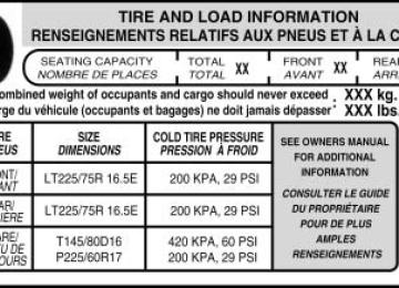
Additional information contained on the tire sidewall for “LT” type tires “LT” type tires have some additional information beyond those of “P” type tires; these differences are described below. Note: Tire Quality Grades do not apply to this type of tire. 1. LT: Indicates a tire, designated by the Tire and Rim Association (T&RA), that is intended for service on light trucks. 2. Load Range/Load Inflation Limits: Indicates the tire’s load-carrying capabilities and its inflation limits. 3. Maximum Load Dual lb. (kg) at psi (kPa) cold: Indicates the maximum load and tire pressure when the tire is used as a dual; defined as four tires on the rear axle (a total of six or more tires on the vehicle). 4. Maximum Load Single lb. (kg) at psi (kPa) cold: Indicates the maximum load and tire pressure when the tire is used as a single; defined as two tires (total) on the rear axle.
161
2009 05+ Mustang (197) Owners Guide USA (fus)
Tires, Wheels and Loading
Information on “T” type tires “T” type tires have some additional information beyond those of “P” type tires; these differences are described below: T145/80D16 is an example of a tire size. Note: The temporary tire size for your vehicle may be different from this example. Tire Quality Grades do not apply to this type of tire. 1. T: Indicates a type of tire, designated by the Tire and Rim Association (T&RA), that is intended for temporary service on cars, SUVs, minivans and light trucks. 2. 145: Indicates the nominal width of the tire in millimeters from sidewall edge to sidewall edge. In general, the larger the number, the wider the tire. 3. 80: Indicates the aspect ratio which gives the tire’s ratio of height to width. Numbers of 70 or lower indicate a short sidewall. 4. D: Indicates a “diagonal” type tire. R: Indicates a “radial” type tire. 5. 16: Indicates the wheel or rim diameter in inches. If you change your wheel size, you will have to purchase new tires to match the new wheel diameter.
Location of the tire label You will find a Tire Label containing tire inflation pressure by tire size and other important information located on the B-Pillar or the edge of the driver’s door. Refer to the payload description and graphic in the Vehicle loading — with and without a trailer section.
162
2009 05+ Mustang (197) Owners Guide USA (fus)
Tires, Wheels and Loading
TIRE PRESSURE MONITORING SYSTEM (TPMS) Each tire, including the spare (if provided), should be checked monthly when cold and inflated to the inflation pressure recommended by the vehicle manufacturer on the vehicle placard or tire inflation pressure label. (If your vehicle has tires of a different size than the size indicated on the vehicle placard or tire inflation pressure label, you should determine the proper tire inflation pressure for those tires.) As an added safety feature, your vehicle has been equipped with a tire pressure monitoring system (TPMS) that illuminates a low tire pressure telltale when one or more of your tires is significantly under-inflated. Accordingly, when the low tire pressure telltale illuminates, you should stop and check your tires as soon as possible, and inflate them to the proper pressure. Driving on a significantly under-inflated tire causes the tire to overheat and can lead to tire failure. Under-inflation also reduces fuel efficiency and tire tread life, and may affect the vehicle’s handling and stopping ability. Please note that the TPMS is not a substitute for proper tire maintenance, and it is the driver’s responsibility to maintain correct tire pressure, even if under-inflation has not reached the level to trigger illumination of the TPMS low tire pressure telltale. Your vehicle has also been equipped with a TPMS malfunction indicator to indicate when the system is not operating properly. The TPMS malfunction indicator is combined with the low tire pressure telltale. When the system detects a malfunction, the telltale will flash for approximately one minute and then remain continuously illuminated. This sequence will continue upon subsequent vehicle start-ups as long as the malfunction exists. When the malfunction indicator is illuminated, the system may not be able to detect or signal low tire pressure as intended. TPMS malfunctions may occur for a variety of reasons, including the installation of replacement or alternate tires or wheels on the vehicle that prevent the TPMS from functioning properly. Always check the TPMS malfunction telltale after replacing one or more tires or wheels on your vehicle to ensure that the replacement or alternate tires and wheels allow the TPMS to continue to function properly.
163
2009 05+ Mustang (197) Owners Guide USA (fus)
Tires, Wheels and Loading
The Tire Pressure Monitoring System complies with part 15 of the FCC rules and with RSS-210 of Industry Canada. Operation is subject to the following two conditions: (1) This device may not cause harmful interference, and (2) This device must accept any interference received, including interference that may cause undesired operation.
WARNING: The Tire Pressure Monitoring System is NOT a substitute for manually checking tire pressure. The tire pressure
should be checked periodically (at least monthly) using a tire gauge, see Inflating your tires in this chapter. Failure to properly maintain your tire pressure could increase the risk of tire failure, loss of control, vehicle rollover and personal injury.
Changing tires with TPMS Each road tire is equipped with a tire pressure sensor fastened to the inside rim of the wheel. The pressure sensor is covered by the tire and is not visible unless the tire is removed. The pressure sensor is located opposite (180 degrees) from the valve stem. Care must be taken when changing the tire to avoid damaging the sensor. It is recommended that you always have your tires serviced by an authorized dealer. The tire pressure should be checked periodically (at least monthly) using an accurate tire gauge, refer to Inflating your tires in this chapter.
164
2009 05+ Mustang (197) Owners Guide USA (fus)
Tires, Wheels and Loading
Understanding your Tire Pressure Monitoring System (TPMS) The Tire Pressure Monitoring System measures pressure in your four road tires and sends the tire pressure readings to your vehicle. The Low Tire Pressure Warning Lamp will turn ON if the tire pressure is significantly low. Once the light is illuminated, your tires are under inflated and need to be inflated to the manufacturer’s recommended tire pressure. Even if the light turns ON and a short time later turns OFF, your tire pressure still needs to be checked. Visit www.checkmytires.org for additional information. When your temporary spare tire is installed When one of your road tires needs to be replaced with the temporary spare, the TPMS system will continue to identify an issue to remind you that the damaged road wheel/tire needs to be repaired and put back on your vehicle. To restore the full functionality of the Tire Pressure Monitoring System, have the damaged road wheel/tire repaired and remounted on your vehicle. For additional information, refer to Changing tires with TPMS in this section.
165
2009 05+ Mustang (197) Owners Guide USA (fus)
Tires, Wheels and Loading
When you believe your system is not operating properly The main function of the Tire Pressure Monitoring System is to warn you when your tires need air. It can also warn you in the event the system is no longer capable of functioning as intended. Please refer to the following chart for information concerning your Tire Pressure Monitoring System:
Possible cause Customer Action Required
Low Tire Pressure Warning Light Solid Warning Light Tire(s)
under-inflated
1. Check your tire pressure to ensure tires are properly inflated; refer to Inflating your tires in this chapter. 2. After inflating your tires to the manufacturer’s recommended inflation pressure as shown on the Tire Label (located on the edge of driver’s door or the B-Pillar), the vehicle must be driven for at least two minutes over 20 mph (32 km/h) before the light will turn OFF.
Spare tire in use Your temporary spare tire is in use. Repair the damaged road wheel/tire and reinstall it on the vehicle to restore system functionality. For a description on how the system functions, refer to When your temporary spare tire is installed in this section. If your tires are properly inflated and your spare tire is not in use and the light remains ON, have the system inspected by your authorized dealer.
TPMS malfunction
166
2009 05+ Mustang (197) Owners Guide USA (fus)
Low Tire Pressure Warning Light Flashing Warning Light
Tires, Wheels and Loading
Possible cause Customer Action Required
Spare tire in use Your temporary spare tire is in use. Repair the damaged road wheel and re-mount it on the vehicle to restore system functionality. For a description of how the system functions under these conditions, refer to When your temporary spare tire is installed in this section. If your tires are properly inflated and your spare tire is not in use and the TPMS warning light still flashes, have the system inspected by your authorized dealer.
TPMS malfunction
When inflating your tires When putting air into your tires (such as at a gas station or in your garage), the Tire Pressure Monitoring System may not respond immediately to the air added to your tires. It may take up to two minutes of driving over 20 mph (32 km/h) for the light to turn OFF after you have filled your tires to the recommended inflation pressure. How temperature affects your tire pressure The Tire Pressure Monitoring System (TPMS) monitors tire pressure in each pneumatic tire. While driving in a normal manner, a typical passenger tire inflation pressure may increase approximately 2 to 4 psi (14 to 28 kPa) from a cold start situation. If the vehicle is stationary over night with the outside temperature significantly lower than the daytime temperature, the tire pressure may decrease approximately 3 psi (20.7 kPa) for a drop of 30° F (16.6°C) in ambient temperature. This lower pressure value may be detected by the TPMS as being significantly lower than the recommended inflation pressure and activate the TPMS warning for low tire pressure. If the low tire pressure warning light is ON, visually check each tire to verify that no tire is flat. (If one or more tires are flat, repair as necessary.) Check air pressure in the road tires. If any tire is under-inflated, carefully drive the vehicle to the nearest location where air can be added to the tires. Inflate all the tires to the recommended inflation pressure.
167
2009 05+ Mustang (197) Owners Guide USA (fus)
Tires, Wheels and Loading
SNOW TIRES AND CHAINS
WARNING: Driving too fast for conditions creates the possibility of loss of vehicle control. Driving at very high speeds for
extended periods of time may result in damage to vehicle components.
WARNING: Snow tires must be the same size, load index, speed rating as those originally provided by Ford. Use of any tire or
wheel not recommended by Ford can affect the safety and performance of your vehicle, which could result in an increased risk of loss of vehicle control, vehicle rollover, personal injury and death. Additionally, the use of non-recommended tires and wheels could cause steering, suspension, axle or transfer case/power transfer unit failure.
The tires on your vehicle have all weather treads to provide traction in rain and snow. However, in some climates, you may need to use snow tires and chains. Use chains on the tires only in an emergency or if the law requires them. Follow these guidelines when using snow tires and chains: • Chains may damage aluminum wheels. • Use only SAE Class S chains with P215/65R16 tires on the rear of the • Do not use tire chains with size P235/55R17 or 235/50R18 tires. Use of SAE Class S chains or other chain types may damage your vehicle. • Install chains securely, verifying that the chains do not touch any • Drive cautiously. If you hear the chains rub or bang against your
wiring, brake lines or fuel lines.
vehicle only.
vehicle, stop and re-tighten the chains. If this does not work, remove the chains to prevent damage to your vehicle.
• If possible, avoid fully loading your vehicle. • Remove the tire chains when they are no longer needed. Do not use • The suspension insulation and bumpers will help prevent vehicle damage. Do not remove these components from your vehicle when using snow tires and chains.
tire chains on dry roads.
168
2009 05+ Mustang (197) Owners Guide USA (fus)
Tires, Wheels and Loading
VEHICLE LOADING – WITH AND WITHOUT A TRAILER This section will guide you in the proper loading of your vehicle and/or trailer, to keep your loaded vehicle weight within its design rating capability, with or without a trailer. Properly loading your vehicle will provide maximum return of vehicle design performance. Before loading your vehicle, familiarize yourself with the following terms for determining your vehicle’s weight ratings, with or without a trailer, from the vehicle’s Tire Label or Safety Compliance Certification Label: Base Curb Weight – is the weight of the vehicle including a full tank of fuel and all standard equipment. It does not include passengers, cargo, or optional equipment. Vehicle Curb Weight – is the weight of your new vehicle when you picked it up from your authorized dealer plus any aftermarket equipment.
Payload – is the combined weight of cargo and passengers that the vehicle is carrying. The maximum payload for your vehicle can be found on the Tire Label on the B-Pillar or the edge of the driver’s door (vehicles exported outside the US and Canada may not have a Tire Label). Look for “THE COMBINED WEIGHT OF OCCUPANTS AND CARGO SHOULD NEVER EXCEED XXX kg OR XXX lb.” for maximum payload. The payload listed on the Tire Label is the maximum payload for the vehicle as built by the assembly plant. If any aftermarket or authorized-dealer installed equipment has been installed on the vehicle, the weight of the equipment must be subtracted from the payload listed on the Tire Label in order to determine the new payload.
WARNING: The appropriate loading capacity of your vehicle can be limited either by volume capacity (how much space is
available) or by payload capacity (how much weight the vehicle should carry). Once you have reached the maximum payload of your vehicle, do not add more cargo, even if there is space available. Overloading or improperly loading your vehicle can contribute to loss of vehicle control and vehicle rollover.
169
2009 05+ Mustang (197) Owners Guide USA (fus)
Tires, Wheels and Loading
Example only:
Cargo Weight – includes all weight added to the Base Curb Weight, including cargo and optional equipment. When towing, trailer tongue load weight is also part of cargo weight. GAW (Gross Axle Weight) – is the total weight placed on each axle (front and rear) – including vehicle curb weight and all payload.
170
2009 05+ Mustang (197) Owners Guide USA (fus)
Tires, Wheels and Loading
GAWR (Gross Axle Weight Rating) – is the maximum allowable weight that can be carried by a single axle (front or rear). These numbers are shown on the Safety Compliance Certification Label located on the B-Pillar or the edge of the driver’s door. The total load on each axle must never exceed its GAWR. Note: For trailer towing information refer to Trailer towing found in this chapter or the RV and Trailer Towing Guide provided by your authorized dealer.
GVW (Gross Vehicle Weight) – is the Vehicle Curb Weight + cargo + passengers. GVWR (Gross Vehicle Weight Rating) – is the maximum allowable weight of the fully loaded vehicle (including all options, equipment, passengers and cargo). The GVWR is shown on the Safety Compliance Certification Label located on the B-Pillar or the edge of the driver’s door. The GVW must never exceed the GVWR.
171
2009 05+ Mustang (197) Owners Guide USA (fus)
Tires, Wheels and Loading
WARNING: Exceeding the Safety Compliance Certification Label vehicle weight rating limits could result in substandard vehicle
handling or performance, engine, transmission and/or structural damage, serious damage to the vehicle, loss of control and personal injury.
GCW (Gross Combined Weight) – is the weight of the loaded vehicle (GVW) plus the weight of the fully loaded trailer. GCWR (Gross Combined Weight Rating) – is the maximum allowable weight of the vehicle and the loaded trailer – including all cargo and passengers – that the vehicle can handle without risking damage. (Important: The towing vehicles’ braking system is rated for operation at GVWR, not at GCWR. Separate functional brakes should be used for safe control of towed vehicles and for trailers where the GCW of the towing vehicle plus the trailer exceed the GVWR of the towing vehicle. The GCW must never exceed the GCWR. Maximum Loaded Trailer Weight – is the highest possible weight of a fully loaded trailer the vehicle can tow. It assumes a vehicle with only mandatory options, no cargo (internal or external), a tongue load of 10–15% (conventional trailer), and driver only (150 lb. [68 kg]). Consult your authorized dealer (or the RV and Trailer Towing Guide provided by your authorized dealer) for more detailed information.
WARNING: Do not exceed the GVWR or the GAWR specified on the Safety Compliance Certification Label.
WARNING: Do not use replacement tires with lower load carrying capacities than the original tires because they may
lower the vehicle’s GVWR and GAWR limitations. Replacement tires with a higher limit than the original tires do not increase the GVWR and GAWR limitations.
172
2009 05+ Mustang (197) Owners Guide USA (fus)
Tires, Wheels and Loading
WARNING: Exceeding any vehicle weight rating limitation could result in serious damage to the vehicle and/or personal injury.
Steps for determining the correct load limit: 1. Locate the statement “The combined weight of occupants and cargo should never exceed XXX kg or XXX lbs.” on your vehicle’s placard. 2. Determine the combined weight of the driver and passengers that will be riding in your vehicle. 3. Subtract the combined weight of the driver and passengers from XXX kg or XXX lbs. 4. The resulting figure equals the available amount of cargo and luggage load capacity. For example, if the “XXX” amount equals 1,400 lbs. and there will be five 150 lb. passengers in your vehicle, the amount of available cargo and luggage load capacity is 650 lbs. (1400–750 (5 x 150) = 650 lb.). In metric units (635–340 (5 x 68) = 295 kg.) 5. Determine the combined weight of luggage and cargo being loaded on the vehicle. That weight may not safely exceed the available cargo and luggage load capacity calculated in Step 4. 6. If your vehicle will be towing a trailer, load from your trailer will be transferred to your vehicle. Consult this manual to determine how this reduces the available cargo and luggage load capacity of your vehicle. The following gives you a few examples on how to calculate the available amount of cargo and luggage load capacity: • Another example for your vehicle with 1,400 lb. (635 kg) of cargo and luggage capacity. You decide to go golfing. Is there enough load capacity to carry you, 4 of your friends and all the golf bags? You and four friends average 220 lb. (99 kg) each and the golf bags weigh approximately 30 lb. (13.5 kg) each. The calculation would be: 1,400 - (5 x 220) - (5 x 30) = 1,400 - 1,100 - 150 = 150 lb. Yes, you have enough load capacity in your vehicle to transport four friends and your golf bags. In metric units, the calculation would be: 635 kg - (5 x 99 kg) - (5 x 13.5 kg) = 635 - 495 - 67.5 = 72.5 kg.
• A final example for your vehicle with 1,400 lb. (635 kg) of cargo and luggage capacity. You and one of your friends decide to pick up cement from the local home improvement store to finish that patio you have been planning for the past 2 years. Measuring the inside of the vehicle with the rear seat folded down, you have room for 12-100 lb. (45 kg) bags of cement. Do you have enough load capacity
173
2009 05+ Mustang (197) Owners Guide USA (fus)
Tires, Wheels and Loading
to transport the cement to your home? If you and your friend each weigh 220 lb. (99 kg), the calculation would be: 1,400 - (2 x 220) - (12 x 100) = 1,400 - 440 - 1,200 = - 240 lb. No, you do not have enough cargo capacity to carry that much weight. In metric units, the calculation would be: 635 kg - (2 x 99 kg) - (12 x 45 kg) = 635 - 198 - 540 = -103 kg. You will need to reduce the load weight by at least 240 lb. (104 kg). If you remove 3-100 lb. (45 kg) cement bags, then the load calculation would be: 1,400 - (2 x 220) - (9 x 100) = 1,400 - 440 - 900 = 60 lb. Now you have the load capacity to transport the cement and your friend home. In metric units, the calculation would be: 635 kg - (2 x 99 kg) - (9 x 45 kg) = 635 - 198 - 405 = 32 kg.
The above calculations also assume that the loads are positioned in your vehicle in a manner that does not overload the Front or the Rear Gross Axle Weight Rating specified for your vehicle on the Safety Compliance Certification Label found on the edge of the driver’s door.
TRAILER TOWING Your vehicle is capable of towing a trailer up to 1,000 lb. (454 kg) gross trailer weight with a maximum tongue load of 100 lb. (45 kg). Do not tow a trailer until your vehicle has been driven at least 500 miles (800 km). Towing a trailer places an additional load on your vehicle’s engine, transmission, brakes, tires and suspension. Inspect these components carefully after towing.
WARNING: Do not exceed the GVWR or the GAWR specified on the certification label.
WARNING: Towing trailers beyond the maximum recommended gross trailer weight exceeds the limit of the vehicle and could
result in engine damage, transmission damage, structural damage, loss of vehicle control, vehicle rollover and personal injury.
Preparing to tow Use the proper equipment for towing a trailer and make sure it is properly attached to your vehicle. See your authorized dealer or a reliable trailer dealer if you require assistance.
174
2009 05+ Mustang (197) Owners Guide USA (fus)
Tires, Wheels and Loading
Hitches Do not use hitches that clamp onto the vehicle bumper. Use a load carrying hitch. You must distribute the load in your trailer so that 10–15% of the total weight of the trailer is on the tongue.
Safety chains Always connect the trailer’s safety chains to the frame or hook retainers of the vehicle hitch. To connect the trailer’s safety chains, cross the chains under the trailer tongue and allow slack for turning corners. If you use a rental trailer, follow the instructions that the rental agency gives to you. Do not attach safety chains to the bumper.
Trailer brakes Electric brakes and manual, automatic or surge-type trailer brakes are safe if installed properly and adjusted to the manufacturer’s specifications. The trailer brakes must meet local and Federal regulations.
WARNING: Do not connect a trailer’s hydraulic brake system directly to your vehicle’s brake system. Your vehicle may not have enough braking power and your chances of having a collision greatly increase.
The braking system of the tow vehicle is rated for operation at the GVWR not GCWR.
Trailer lamps Trailer lamps are required on most towed vehicles. Make sure all running lights, brake lights, turn signals and hazard lights are working. Do not splice into the vehicle lamp wiring for trailer lamps. Your vehicle uses an advanced electronic module to control and monitor your vehicle lamps. Splicing into the wiring or attaching wiring to the vehicle bulb. may DISABLE the rear vehicle lamps or cause them not to function properly. See your authorized dealer for proper instructions and equipment for hooking up trailer lamps.
175
2009 05+ Mustang (197) Owners Guide USA (fus)
Tires, Wheels and Loading
Driving while you tow When towing a trailer: • Turn off the speed control. The speed control may shut off automatically when you are towing on long, steep grades. • Consult your local motor vehicle speed regulations for towing a trailer. • Shift out of D (Overdrive) into D (Overdrive cancelled) or a lower gear (3, 2, or 1) when towing up or down steep hills. This will eliminate excessive downshifting and upshifting for optimum fuel economy and transmission cooling. • Anticipate stops and brake gradually. Servicing after towing If you tow a trailer for long distances, your vehicle will require more frequent service intervals. Refer to your scheduled maintenance information for more information.
Trailer towing tips • Practice turning, stopping and backing up before starting on a trip to get the feel of the vehicle trailer combination. When turning, make wider turns so the trailer wheels will clear curbs and other obstacles. • If you are driving down a long or steep hill, shift to a lower gear. Do not apply the brakes continuously, as they may overheat and become less effective.
• Allow more distance for stopping with a trailer attached. • The trailer tongue weight should be 10–15% of the loaded trailer • After you have traveled 50 miles (80 km), thoroughly check your • To aid in engine/transmission cooling and A/C efficiency during hot weather while stopped in traffic, place the gearshift lever in P (Park) (automatic transmission) or N (Neutral) (manual transmissions). • Vehicles with trailers should not be parked on a grade. If you must
hitch, electrical connections and trailer wheel lug nuts.
weight.
park on a grade, place wheel chocks under the trailer’s wheels.
176
2009 05+ Mustang (197) Owners Guide USA (fus)
Tires, Wheels and Loading
RECREATIONAL TOWING Follow these guidelines if you have a need for recreational (RV) towing. An example of recreational towing would be towing your vehicle behind a motorhome. These guidelines are designed to ensure that your transmission is not damaged. All vehicles: Do not tow your vehicle with any wheels on the ground, as vehicle or transmission damage may occur. It is recommended to tow your vehicle with all four (4) wheels off the ground such as when using a car-hauling trailer. Otherwise, no recreational towing is permitted. In case of a roadside emergency with a disabled vehicle, see Wrecker towing in the Roadside Emergencies chapter.
177
2009 05+ Mustang (197) Owners Guide USA (fus)
Driving
STARTING
Positions of the ignition 1. Off — locks the automatic transmission gearshift lever and allows key removal. Note: The ignition key cannot be removed from the ignition unless the gearshift lever is securely latched in P (Park). 2. Accessory — allows the electrical accessories such as the radio to operate while the engine is not running. 3. On — all electrical circuits operational. Warning lights illuminated. Key position when driving. 4. Start — cranks the engine. Release the key as soon as the engine starts.
Preparing to start your vehicle Engine starting is controlled by the powertrain control system. This system meets all Canadian Interference-Causing Equipment standard requirements regulating the impulse electrical field strength of radio noise. When starting a fuel-injected engine, don’t press the accelerator before or during starting. Only use the accelerator when you have difficulty starting the engine. For more information on starting the vehicle, refer to Starting the engine in this chapter.
WARNING: Extended idling at high engine speeds can produce very high temperatures in the engine and exhaust system,
creating the risk of fire or other damage.
WARNING: Do not park, idle, or drive your vehicle in dry grass or other dry ground cover. The emission system heats up the
engine compartment and exhaust system, which can start a fire.
178
2009 05+ Mustang (197) Owners Guide USA (fus)
Driving
WARNING: Do not start your vehicle in a closed garage or in other enclosed areas. Exhaust fumes can be toxic. Always open
the garage door before you start the engine. See Guarding against exhaust fumes in this chapter for more instructions.
WARNING: If you smell exhaust fumes inside your vehicle, have your dealer inspect your vehicle immediately. Do not drive if you
smell exhaust fumes.
Important safety precautions A computer system controls the engine’s idle revolutions per minute (RPM). When the engine starts, the idle RPM runs higher than normal in order to warm the engine. If the engine idle speed does not slow down automatically, have the vehicle checked. Do not allow the vehicle to idle for more than 10 minutes at the higher engine RPM. Before starting the vehicle: 1. Make sure all vehicle occupants have buckled their safety belts. For more information on safety belts and their proper usage, refer to the Seating and Safety Restraints chapter. 2. Make sure the headlamps and vehicle accessories are off. If starting a vehicle with an automatic transmission:
179
2009 05+ Mustang (197) Owners Guide USA (fus)
Driving • Make sure the gearshift is in P
(Park).
• Make sure the parking brake is
set.
If starting a vehicle with a manual transmission: • Make sure the parking brake is • Push the clutch pedal to the floor
set.
180
2009 05+ Mustang (197) Owners Guide USA (fus)
3. Turn the key to 3 (on) without turning the key to 4 (start).
Driving
Some warning lights will briefly illuminate. See Warning lights and chimes in the Instrument Cluster chapter for more information regarding the warning lights.
Starting the engine 1. Turn the key to 3 (on) without turning the key to 4 (start). If there is difficulty in turning the key, rotate the steering wheel until the key turns freely. 2. Turn the key to 4 (start), then release the key as soon as the engine starts.
Note: If the engine does not start within five seconds on the first try, turn the key to off, wait 10 seconds and try again. If the engine still fails to start, press and hold the accelerator to the floor and try again; this will allow the engine to crank with the fuel shut off in case the engine is flooded with fuel.
Guarding against exhaust fumes Carbon monoxide is present in exhaust fumes. Take precautions to avoid its dangerous effects.
WARNING: If you smell exhaust fumes inside your vehicle, have your dealer inspect your vehicle immediately. Do not drive if you
smell exhaust fumes.
181
2009 05+ Mustang (197) Owners Guide USA (fus)
Driving
Important ventilating information If the engine is idling while the vehicle is stopped for a long period of time, open the windows at least one inch (2.5 cm) or adjust the heating or air conditioning to bring in fresh air.
ENGINE BLOCK HEATER (IF EQUIPPED) An engine block heater warms the engine coolant which aids in starting and allows the heater/defroster system to respond quickly. If your vehicle is equipped with this system, your equipment includes a heater element which is installed in your engine block and a wire harness which allows the user to connect the system to a grounded 120 volt a/c electrical source. The block heater system is most effective when outdoor temperatures reach below 0°F (-18°C).
WARNING: Failure to follow engine block heater instructions could result in property damage or physical injury.
WARNING: To reduce the risk of electrical shock, do not use your heater with ungrounded electrical systems or two-pronged
(cheater) adapters.
Prior to using the engine block heater, follow these recommendations for proper and safe operation: • For your safety, use an outdoor extension cord that is product certified by Underwriter’s Laboratory (UL) or Canadian Standards Association (CSA). Use only an extension cord that can be used outdoors, in cold temperatures, and is clearly marked ⬙Suitable for Use with Outdoor Appliances.⬙ Never use an indoor extension cord outdoors; it could result in an electric shock or fire hazard.
• Use a 16 gauge outdoor extension cord, minimum. • Use as short an extension cord as possible. • Do not use multiple extension cords. Instead, use one extension cord which is long enough to reach from the engine block heater cord to the outlet without stretching. • Make certain that the extension cord is in excellent condition (not patched or spliced). Store your extension cord indoors at temperatures above 32°F (0°C). Outdoor conditions can deteriorate extension cords over a period of time.
182
2009 05+ Mustang (197) Owners Guide USA (fus)
Driving
• To reduce the risk of electrical shock, do not use your heater with ungrounded electrical systems or two pronged (cheater) adapters. Also ensure that the block heater, especially the cord, is in good condition before use.
• Make sure that when in operation, the extension cord plug /engine block heater cord plug connection is free and clear of water in order to prevent possible shock or fire. • Be sure that areas where the vehicle is parked are clean and clear of all combustibles such as petroleum products, dust, rags, paper and similar items.
• Be sure that the engine block heater, heater cord and extension cord are solidly connected. A poor connection can cause the cord to become very hot and may result in an electrical shock or fire. Be sure to check for heat anywhere in the electrical hookup once the system has been operating for approximately a half hour. • Finally, have the engine block heater system checked during your fall
tune-up to be sure it’s in good working order.
How to use the engine block heater Ensure the receptacle terminals are clean and dry prior to use. To clean them, use a dry cloth. Depending on the type of factory installed equipment, your engine block heater system may consume anywhere between 400 watts or 1000 watts of energy per hour. Your factory installed block heater system does not have a thermostat; however, maximum temperature is attained after approximately three hours of operation. Block heater operation longer than three hours will not improve system performance and will unnecessarily use additional electricity. Make sure system is unplugged and properly stowed before driving the vehicle. While not in use, make sure the protective cover seals the prongs of the engine block heater cord plug.
183
2009 05+ Mustang (197) Owners Guide USA (fus)
Driving
BRAKES Occasional brake noise is normal. If a metal-to-metal, continuous grinding or continuous squeal sound is present, the brake linings may be worn-out and should be inspected by an authorized dealer. If the vehicle has continuous vibration or shudder in the steering wheel while braking, the vehicle should be inspected by an authorized dealer. Refer to Brake system warning light in the Instrument Cluster chapter for information on the brake system warning light.
BRAKE
ABS
Four-wheel anti-lock brake system (ABS) (if equipped) Your vehicle may be equipped with an Anti-lock Braking System (ABS). This system helps you maintain steering control during emergency stops by keeping the brakes from locking. Noise from the ABS pump motor and brake pedal pulsation may be observed during ABS braking; any pulsation or mechanical noise you may feel or hear is normal. ABS warning lamp The ABS lamp in the instrument cluster momentarily illuminates when the ignition is turned on. If the light does not illuminate during start up, remains on or flashes, the ABS may be disabled and may need to be serviced. Even when the ABS is disabled, normal braking is still effective. If your BRAKE warning lamp illuminates with the parking brake released, have your brake system serviced immediately. Using ABS When hard braking is required, apply continuous force on the brake pedal; do not pump the brake pedal since this will reduce the effectiveness of the ABS and will increase your vehicle’s stopping distance. The ABS will be activated immediately, allowing you to retain steering control during hard braking and on slippery surfaces. However, the ABS does not decrease stopping distance.
BRAKE
184
2009 05+ Mustang (197) Owners Guide USA (fus)
Parking brake To set the parking brake (1), pull the parking brake handle up as far as possible.
Driving
The BRAKE warning lamp will illuminate and will remain illuminated until the parking brake is released.
BRAKE
To release, press and hold the button (2), pull the handle up slightly, then push the handle down.
WARNING: Always set the parking brake fully and make sure that the gearshift is securely latched in P (Park) (automatic
transmission) or in 1 (First) (manual transmission).
WARNING: If the parking brake is fully released, but the brake warning lamp remains illuminated, the brakes may not be
working properly. See your authorized dealer as soon as possible.
TRACTION CONTROL™ (IF EQUIPPED) Your vehicle may be equipped with a Traction Control™ system. This system helps you maintain the stability and steerability of your vehicle, especially on slippery road surfaces such as snow- or ice-covered roads and gravel roads. The system operates by detecting and controlling wheel spin. The system borrows many of the electronic and mechanical elements already present in the Anti-lock Braking System (ABS). Wheel-speed sensors allow excess rear wheel spin to be detected by the Traction Control™ portion of the ABS computer. Any excessive wheel spin is controlled by automatically applying and releasing the rear brakes in conjunction with engine torque reductions.
185
2009 05+ Mustang (197) Owners Guide USA (fus)
Driving
The Traction Control™ system will allow your vehicle to make better use of available traction on slippery surfaces while you are trying to accelerate or while your foot is on the accelerator pedal. The system is a driver aid which makes your vehicle easier to handle primarily on snow and ice covered roads. During Traction Control™ operation, the traction control active light will illuminate. If your vehicle is equipped with a message center, a message will display during Traction Control™ operation. You may hear an electric motor type of sound coming from the engine compartment and the engine will not “rev-up” when you push further on the accelerator. This is normal system behavior and should be no reason for concern. The Traction Control™ switch, located above the radio, illuminates when the system is off. The Traction Control™ system will automatically turn on every time the ignition is turned off and on. If you should become stuck in snow or ice or on a very slippery road surface, try switching the Traction Control™ system off. This may allow excess wheel spin to “dig” the vehicle out and enable a successful “rocking” maneuver. The traction control on/off status is shown by an indicator lamp on the traction control switch. If the system is off, the indicator will be illuminated. If a system fault is detected, the traction control active light will illuminate, the Traction Control™ button will also illuminate and will not turn the system on or off and your vehicle should be serviced by an authorized dealer.
WARNING: Aggressive driving in any road conditions can cause you to lose control of your vehicle increasing the risk of severe
personal injury or property damage. The occurrence of a Traction Control™ event is an indication that at least some of the tires have exceeded their ability to grip the road; this may lead to an increased risk of loss of vehicle control, vehicle rollover, personal injury and death. If you experience a severe road event, SLOW DOWN.
186
2009 05+ Mustang (197) Owners Guide USA (fus)
Driving
STEERING To help prevent damage to the power steering system: • Never hold the steering wheel at its furthest turning points (until it stops) for more than a few seconds when the engine is running. • Do not operate the vehicle with a low power steering fluid level • Some noise is normal during operation. If the noise is excessive, check
(below the MIN mark on the reservoir).
for a low power steering fluid level before seeking service by your authorized dealer. • Heavy or uneven steering efforts may be caused by a low power
steering fluid level. Check for a low power steering fluid level before seeking service by your authorized dealer. • Do not fill the power steering fluid reservoir above the MAX mark on
the reservoir.
If the power steering system breaks down (or if the engine is turned off), you can steer the vehicle manually, but it takes more effort. If the steering wanders or pulls, check for: • an improperly inflated tire • uneven tire wear • loose or worn suspension components • loose or worn steering components • improper steering alignment A high crown in the road or high crosswinds may also make the steering seem to wander/pull.
TRACTION-LOK™ AXLE (IF EQUIPPED) This axle provides added traction on slippery surfaces, particularly when one wheel is on a poor traction surface. Under normal conditions, the Traction-Lok™ axle functions like a standard rear axle. Extended use of other than the manufacturer’s specified size tires on a Traction-Lok™ rear axle could result in a permanent reduction in effectiveness. This loss of effectiveness does not affect normal driving and should not be noticeable to the driver.
187
2009 05+ Mustang (197) Owners Guide USA (fus)
Driving
AUTOMATIC TRANSMISSION OPERATION (IF EQUIPPED)
Brake-shift interlock This vehicle is equipped with a brake-shift interlock feature that prevents the gearshift lever from being moved from P (Park) when the ignition is in the on position unless the brake pedal is depressed. If you cannot move the gearshift lever out of P (Park) with ignition in the on position and the brake pedal depressed: 1. Apply the parking brake, turn ignition key to off, then remove the key. 2. Using a flat head screwdriver, remove the plastic cover. 3. Insert the ignition key and push it straight down to release the interlock.
4. Apply the parking brake, then shift to N (Neutral). 5. Start the vehicle. If it is necessary to use the above procedure to move the gearshift lever, it is possible that a fuse has blown or the vehicle’s brakelamps are not operating properly. Refer to Fuses and relays in the Roadside Emergencies chapter.
WARNING: Do not drive your vehicle until you verify that the brakelamps are working.
WARNING: Always set the parking brake fully and make sure the gearshift is latched in P (Park). Turn the ignition to the off
position and remove the key whenever you leave your vehicle.
WARNING: If the parking brake is fully released, but the brake warning lamp remains illuminated, the brakes may not be
working properly. See your authorized dealer.
188
2009 05+ Mustang (197) Owners Guide USA (fus)
Understanding the gearshift positions of the 5–speed automatic transmission
Driving
This vehicle is equipped with an Adaptive Transmission Control Strategy. This Adaptive Transmission Control Strategy offers the optimal transmission operation and shift quality. When the vehicle’s battery has been disconnected for any type of service or repair, the transmission will need to relearn the normal shift strategy parameters, much like having to reset your radio stations when your vehicle battery has been disconnected. The Adaptive Transmission Control Strategy allows the transmission to relearn these operating parameters. This learning process could take several transmission upshifts and downshifts; during this learning process, slightly firmer shifts may occur. After this learning process, normal shift feel and shift scheduling will resume. P (Park) This position locks the transmission and prevents the rear wheels from turning. To put your vehicle in gear: • Start the engine • Depress the brake pedal • Move the gearshift lever into the desired gear
189
2009 05+ Mustang (197) Owners Guide USA (fus)
Driving
To put your vehicle in P (Park): • Come to a complete stop • Move the gearshift lever and securely latch it in P (Park)
WARNING: Always set the parking brake fully and make sure the gearshift is latched in P (Park). Turn the ignition to the
LOCK position and remove the key whenever you leave your vehicle.
R (Reverse) With the gearshift lever in R (Reverse), the vehicle will move backward. Always come to a complete stop before shifting into and out of R (Reverse). N (Neutral) With the gearshift lever in N (Neutral), the vehicle can be started and is free to roll. Hold the brake pedal down while in this position. D (Drive) with Overdrive The normal driving position for the best fuel economy. Transmission operates in gears one through five. D (Drive) without Overdrive D (Drive) with Overdrive can be deactivated by pressing the transmission control switch on the right side of the shift handle.
• This position allows for all forward gears except Overdrive. • O/D OFF lamp is illuminated.
O/D OFF
• Provides engine braking. • Use when driving conditions cause excessive shifting from O/D to
other gears. Examples: heavy city traffic where continuous shifting in
190
2009 05+ Mustang (197) Owners Guide USA (fus)
Driving
and out of overdrive occurs, hilly terrain, heavy loads, trailer towing and when engine braking is required. • To return to Overdrive mode, press the transmission control switch. • Overdrive mode is automatically returned each time the key is turned
The O/D OFF lamp will not be illuminated.
off.
3 (Third) This position allows for third gear only. • Provides engine braking. • To return to D (Drive) without Overdrive, move the transmission shift • Selecting 3 (Third) at higher speeds will cause the transmission to
lever into the D (Drive) position.
downshift to third gear at the appropriate vehicle speed.
2 (Second) This position allows for second gear only. • Provides engine braking. • Use to start-up on slippery roads. • To return to D (Drive) without Overdrive or 3 (Third), move the transmission shift lever into the D (Drive) or 3 (Third) position. • Selecting 2 (Second) at higher speeds will cause the transmission to
downshift to second gear at the appropriate vehicle speed.
1 (First) This position allows for first gear only. • Provides maximum engine braking. • Will not downshift into first gear at high speeds; will cause the
transmission to downshift to a lower gear, then allows for first gear when the vehicle reaches slower speeds.
Forced downshifts • Allowed in Overdrive or Drive. • Depress the accelerator to the floor. • Allows transmission to select an appropriate gear. If your vehicle gets stuck in mud or snow If your vehicle gets stuck in mud or snow, it may be rocked out by shifting between forward and reverse gears, stopping between shifts in a steady pattern. Press lightly on the accelerator in each gear.
191
2009 05+ Mustang (197) Owners Guide USA (fus)
Driving
Do not rock the vehicle if the engine is not at normal operating temperature or damage to the transmission may occur. Do not rock the vehicle for more than a minute or damage to the transmission and tires may occur, or the engine may overheat. MANUAL TRANSMISSION OPERATION (IF EQUIPPED)
Using the clutch Manual transmission vehicles have a starter interlock that prevents cranking the engine unless the clutch pedal is fully depressed. To start the vehicle: 1. Make sure the parking brake is fully set. 2. Press the clutch pedal to the floor, then put the gearshift lever in the neutral position.
4 R
3. Start the engine. 4. Press the brake pedal and move the gearshift lever to the desired gear; 1 (First) or R (Reverse). 5. Release the parking brake, then slowly release the clutch pedal while slowly pressing on the accelerator. During each shift, the clutch pedal must be fully depressed to the floor. Make sure the floor mat is properly positioned so it doesn’t interfere with the full extension of the clutch pedal. Failure to fully depress the clutch pedal to the floor may cause increased shift efforts, prematurely wear transmission components or damage the transmission.
192
2009 05+ Mustang (197) Owners Guide USA (fus)
Driving
Do not drive with your foot resting on the clutch pedal or use the clutch pedal to hold your vehicle at a standstill while waiting on a hill. These actions will severely reduce the life of the clutch and could nullify a clutch warranty claim.
Recommended shift speeds Do not downshift into 1 (First) when your vehicle is moving faster than 15 mph (24 km/h). This will damage the clutch. Upshift according to the following chart:
Upshifts when accelerating (recommended for best fuel
1 - 2
2 - 3
3 - 4
4 - 5economy) Shift from:
11 mph (18 km/h) 19 mph (31 km/h) 30 mph (48 km/h) 40 mph (64 km/h)
Reverse 1. Make sure that your vehicle is at a complete stop before you shift into R (Reverse). Failure to do so may damage the transmission. 2. Move the gearshift lever into the neutral position and wait at least three seconds before shifting into R (Reverse).
4 R
• The gearshift lever can only be moved into R (Reverse) by moving it from left of 3 (Third) and 4 (Fourth) before shifting into R (Reverse). This is a lockout feature that protects the transmission from accidentally being shifted into R (Reverse) from 5 (Overdrive).
193
2009 05+ Mustang (197) Owners Guide USA (fus)
Driving
Parking your vehicle 1. Apply the brake and shift into the neutral position. 2. Fully apply the parking brake, then shift into 1 (First). 3. Turn the ignition off.
WARNING: Do not park your vehicle in Neutral, it may move unexpectedly and injure someone. Use 1 (First) gear and set the
parking brake fully.
DRIVING THROUGH WATER If driving through deep or standing water is unavoidable, proceed very slowly especially when the depth is not known. Never drive through water that is higher than the bottom of the wheel rims (for cars) or the bottom of the hubs (for trucks).
When driving through water, traction or brake capability may be limited. Also, water may enter your engine’s air intake and severely damage your engine or your vehicle may stall. Driving through deep water where the transmission vent tube is submerged may allow water into the transmission and cause internal transmission damage. Once through the water, always dry the brakes by moving your vehicle slowly while applying light pressure on the brake pedal. Wet brakes do not stop the vehicle as quickly as dry brakes.
194
2009 05+ Mustang (197) Owners Guide USA (fus)
Roadside Emergencies
ROADSIDE ASSISTANCE
Getting roadside assistance To fully assist you should you have a vehicle concern, Ford Motor Company offers a complimentary roadside assistance program. This program is separate from the New Vehicle Limited Warranty. The service is available: • 24–hours, seven days a week • for the coverage period listed on the Roadside Assistance Card
included in your Owner Guide portfolio.
responsibility)
supplied with a tire inflation kit)
Roadside assistance will cover: • a flat tire change with a good spare (except vehicles that have been • battery jump start • lock-out assistance (key replacement cost is the customer’s • fuel delivery – Independent Service Contractors, if not prohibited by state, local or municipal law shall deliver up to 2.0 gallons (7.5L) of gasoline or 5 gallons (18.9L) of diesel fuel to a disabled vehicle. Fuel delivery service is limited to two no-charge occurrences within a 12-month period. • winch out – available within 100 feet (30.5 meters) of a paved or • towing – Ford/Mercury/Lincoln eligible vehicle towed to an authorized dealer within 35 miles (56.3 km) of the disablement location or to the nearest authorized dealer. If a member requests to be towed to an authorized dealer more than 35 miles (56.3 km) from the disablement location, the member shall be responsible for any mileage costs in excess of 35 miles (56.3 km).
county maintained road, no recoveries.
Trailers shall be covered up to $200 if the disabled eligible vehicle requires service at the nearest authorized dealer. If the trailer is disabled, but the towing vehicle is operational, the trailer does not qualify for any roadside services.
195
2009 05+ Mustang (197) Owners Guide USA (fus)
Roadside Emergencies
Canadian customers refer to your Customer Information Guide for information on: • coverage period • exact fuel amounts • towing of your disabled vehicle • emergency travel expense reimbursement • travel planning benefits In Canada, for uninterrupted Roadside Assistance coverage, you may purchase extended coverage prior to your Basic Warranty’s Roadside Assistance expiring. For more information and enrollment, contact 1–877–294–2582 or visit our website at www.ford.ca.
Using roadside assistance Complete the roadside assistance identification card and place it in your wallet for quick reference. In the United States, this card is found in the Owner Guide portfolio in the glove compartment. In Canada, the card is found in the Customer Information Guide in the glove compartment. U.S. Ford, Mercury and Lincoln vehicle customers who require Roadside Assistance, call 1-800-241-3673. Canadian customers who require roadside assistance, call 1-800-665-2006. If you need to arrange roadside assistance for yourself, Ford Motor Company will reimburse a reasonable amount for towing to the nearest dealership within 35 miles. To obtain reimbursement information, U.S. Ford, Mercury and Lincoln vehicle customers call 1-800-241-3673. Customers will be asked to submit their original receipts. Canadian customers who need to obtain reimbursement information, call 1–800–665–2006.
HAZARD FLASHER CONTROL The hazard flasher is located on the instrument panel by the radio. The hazard flashers will operate when the ignition is in any position or if the key is not in the ignition. Push in the flasher control and all front and rear direction signals will flash. Press the flasher control again to turn them off. Use it when your vehicle is disabled and is creating a safety hazard for other motorists.
196
2009 05+ Mustang (197) Owners Guide USA (fus)
Roadside Emergencies
Note: With extended use, the flasher may run down your battery.
FUEL PUMP SHUT-OFF SWITCH FUEL RESET This device stops the electric fuel pump from sending fuel to the engine when your vehicle has had a substantial jolt. After an accident, if the engine cranks but does not start, this switch may have been activated. The fuel pump shut-off switch is located in the driver’s footwell, by the hood release To reset the switch: 1. Turn the ignition off. 2. Check the fuel system for leaks. 3. If no leaks are apparent, reset the switch by pushing in on the reset button. 4. Turn the ignition on. 5. Wait a few seconds and return the key to off. 6. Make another check for leaks.
FUSES AND RELAYS
Fuses If electrical components in the vehicle are not working, a fuse may have blown. Blown fuses are identified by a broken wire within the fuse. Check the appropriate fuses before replacing any electrical components. Note: Always replace a fuse with one that has the specified amperage rating. Using a fuse with a higher amperage rating can cause severe wire damage and could start a fire.
15
197
2009 05+ Mustang (197) Owners Guide USA (fus)
Roadside Emergencies
Standard fuse amperage rating and color
COLOR
Fuse rating
2A 3A 4A 5A 7.5A 10A 15A 20A 25A 30A 40A 50A 60A 70A 80A
Mini fuses
Grey Violet Pink Tan
Brown
Red Blue Yellow Natural Green
— — — — —
Standard
fuses
Grey Violet Pink Tan
Brown
Red Blue Yellow Natural Green
— — — — —
Maxi fuses
— — — — — — —
Yellow
—
Green Orange
Red Blue Tan
Natural
Cartridge
maxi fuses
— — — — — — — Blue — Pink Green Red Yellow
—
Black
Fuse link cartridge
— — — — — — — Blue — Pink Green Red Yellow Brown Black
Passenger compartment fuse panel The fuse panel is located in the lower passenger side area behind the kick panel. Remove the trim panel cover and the fuse cover to access the fuses. To remove a fuse, use the fuse puller tool provided to the left of the fuses and relays.
198
2009 05+ Mustang (197) Owners Guide USA (fus)
Roadside Emergencies
The fuses are coded as follows:
Fuse/Relay Location
10
11
12
13
14
15
16Fuse Amp
Rating
Mini relay
— 10A 5A — 5A 10A
10A
— 5A
— 5A — 5A 10A 5A
Protected Circuits
Accessory delay #1
Not used Wiper power/Blower motor relay Power mirrors Not used Accessory delay feeds Electrochromic mirror/ Ambient lighting Cluster, Data Link Connector (DLC) Not used Intrusion Sensing Module (ISM), Climate control Not used Climate control, Ignition Not used A/C cycle switch Brake On/Off (BOO) power Cluster199
2009 05+ Mustang (197) Owners Guide USA (fus)
Roadside Emergencies
Fuse/Relay Location
17
18
1920
21Fuse Amp
Rating
10A
10A 5A
10A 10A
Protected Circuits
Restraint Control Module (RCM), Passenger Occupant Detection System (PODS), Passenger Air bag Deactivation Indicator (PADI) Anti-lock Brake System (ABS) Powertrain Control Module (PCM) relay, Passive Anti-Theft System (PATS), Instrument cluster airbag warning lamp Radio (Start) Starter relay
Power distribution box The power distribution box is located in the engine compartment. The power distribution box contains high-current fuses that protect your vehicle’s main electrical systems from overloads. Do not probe the contacts for the fuses and relays in the power distribution box as damage will occur, causing improper, or loss of, electrical functionality.
WARNING: Always disconnect the battery before servicing high current fuses.
WARNING: To reduce risk of electrical shock, always replace the cover to the Power Distribution Box before reconnecting the
battery or refilling fluid reservoirs.
If the battery has been disconnected and reconnected, refer to the Battery section of the Maintenance and Specifications chapter.
200
2009 05+ Mustang (197) Owners Guide USA (fus)
Roadside Emergencies
The high-current fuses are coded as follows.
Fuse/Relay Location
Fuse Amp
Rating
Protected Circuits
10
1112
13
—
30A* 40A* 30A* 30A* 30A*
30A* 40A* 30A*
30A* 30A*
30A*
40A*
Not used Climate control blower Cooling fan Starter Driver front window motor Rear amplifier (Shaker 1000
radio) Passenger front window motor Anti-lock Brake System (ABS) #1
Rear amplifier (Shaker 1000
radio) Wipers Driver rear window motor (Convertible only) Passenger rear window motor (Convertible only) Convertible top201
2009 05+ Mustang (197) Owners Guide USA (fus)
Roadside Emergencies
Fuse/Relay Location
14
15
1620
21
22
23
24
25
26
27
28
29
30
31
32
33
34
39
40
41
42
43
44
45
46
47
48
49
50Fuse Amp
Protected Circuits
Rating 30A* 30A* 30A*
Mini relay Micro relay Micro relay
—
Micro relay Mini relay Micro relay Micro relay Mini relay Mini relay Micro relay Mini relay Mini relay Mini relay Micro relay
15A** 15A** 15A** 15A** 10A** 10A** 10A** 25A** 15A**
—
15A** 15A**
Driver seat Passenger seat Front amplifier (Shaker 500/1000
radios) PCM Fuel pump Starter Not used A/C clutch Cooling fan (High-speed) Horn High beams Cooling fan (Low-speed) Rear defroster Fog lamps Convertible top (Up) Climate control blower Convertible top (Down) Decklid Engine #4
Engine #2
Fuel pump Engine #3
Alternator Delayed accessory PCM Horn Engine #1
Not used A/C clutch High beams202
2009 05+ Mustang (197) Owners Guide USA (fus)
Roadside Emergencies
Fuse Amp
Protected Circuits
Rating 10A** 30A** Diode 20A** 20A** 20A** 20A** 15A** 30A**
—
20A**
20A**
30A**
20A** 30A** 25A** 30A**
20A**
Convertible top Rear defroster PCM Left HID headlamp Right HID headlamp Radio, SDARS Decklid release Fog lamps SJB #5 (Passenger compartment fuse box) Not used Power point #1 (Instrument panel) SJB #7 (Passenger compartment fuse box) SJB #6 (Passenger compartment fuse box) Power point #2 (Console) ABS #2
Heated seats SJB #4 (Passenger compartment fuse box) IgnitionFuse/Relay Location
51
52
53
54
55
56
57
58
5960
6162
63
64
65
66
6768
* Cartridge Fuses ** Mini Fuses
Auxiliary relay with heated seats (if equipped) On heated seat equipped vehicles, there is a relay box located behind the headlamp switch area containing two micro relays for the driver and passenger heated seats.
203
2009 05+ Mustang (197) Owners Guide USA (fus)
Roadside Emergencies
Auxiliary relay with HID headlamps (if equipped)
1. Left HID headlamp 2. Right HID headlamp 3. Not used 4. Not used On vehicles equipped with HID headlamps, an auxiliary relay box is located under the hood on the right hand side front of the engine compartment. This auxiliary relay box contains the left front and right front HID headlamp relays.
CHANGING A FLAT TIRE If you get a flat tire while driving: • do not brake heavily. • gradually decrease the vehicle’s speed. • hold the steering wheel firmly. • slowly move to a safe place on the side of the road. Your vehicle may be equipped with a conventional spare tire that is different in one or more of the following: type, brand, size, speed rating and tread design. If this is the case, this dissimilar spare tire is still rated for your vehicle loads (GAWR and GVWR). This temporary spare tire is not equipped with a Tire Pressure Monitor System (TPMS) sensor. Note: The tire pressure monitoring system (TPMS) indicator light will illuminate when the spare is in use. To restore the full functionality of the TPMS system, all road wheels equipped with the tire pressure monitoring sensors must be mounted on the vehicle. Have a flat tire serviced by an authorized dealer in order to prevent damage to the TPMS sensor, refer to Tire Pressure Monitoring System
204
2009 05+ Mustang (197) Owners Guide USA (fus)
Roadside Emergencies
(TPMS) in the Tires, Wheels, and Loading chapter. Replace the spare tire with a road tire as soon as possible. During repairing or replacing of the flat tire, have the authorized dealer inspect the TPMS sensor for damage.
WARNING: The use of tire sealants may damage your Tire Pressure Monitoring System and should only be used if it is
supplied with your vehicle as part of the original temporary mobility kit.
WARNING: Refer to Tire Pressure Monitoring System (TPMS) in the Tire, Wheels and Loading chapter for important
information. If the tire pressure monitor sensor becomes damaged, it will no longer function.
Dissimilar spare tire/wheel information
WARNING: Failure to follow these guidelines could result in an increased risk of loss of vehicle control, injury or death.
If you have a dissimilar spare tire/wheel, then it is intended for temporary use only. This means that if you need to use it, you should replace it as soon as possible with a road tire/wheel that is the same size and type as the road tires and wheels that were originally provided by Ford. If the dissimilar spare tire or wheel is damaged, it should be replaced rather than repaired. A dissimilar spare tire/wheel is defined as a spare tire and/or wheel that is different in brand, size or appearance from the road tires and wheels and can be one of three types: 1. T-type mini-spare: This spare tire begins with the letter “T” for tire size and may have “Temporary Use Only” molded in the sidewall 2. Full-size dissimilar spare with label on wheel: This spare tire has a label on the wheel that states: “THIS TIRE AND WHEEL FOR TEMPORARY USE ONLY” When driving with one of the dissimilar spare tires listed above, do not: • Exceed 50 mph (80 km/h) • Load the vehicle beyond maximum vehicle load rating listed on the • Tow a trailer
Safety Compliance Label
205
2009 05+ Mustang (197) Owners Guide USA (fus)
tire
Roadside Emergencies • Use snow chains on the end of the vehicle with the dissimilar spare • Use more than one dissimilar spare tire at a time • Use commercial car washing equipment • Try to repair the dissimilar spare tire Use of one of the dissimilar spare tires listed above at any one wheel location can lead to impairment of the following: • Handling, stability and braking performance • Comfort and noise • Ground clearance and parking at curbs • Winter weather driving capability • Wet weather driving capability 3. Full-size dissimilar spare without label on wheel When driving with the full-size dissimilar spare tire/wheel, do not: • Exceed 70 mph (113 km/h) • Use more than one dissimilar spare tire/wheel at a time • Use commercial car washing equipment • Use snow chains on the end of the vehicle with the dissimilar spare
tire/wheel
The usage of a full-size dissimilar spare tire/wheel can lead to impairment of the following: • Handling, stability and braking performance • Comfort and noise • Ground clearance and parking at curbs • Winter weather driving capability • Wet weather driving capability • All-Wheel driving capability (if applicable) • Load leveling adjustment (if applicable) When driving with the full-size dissimilar spare tire/wheel additional caution should be given to: • Towing a trailer • Driving vehicles equipped with a camper body • Driving vehicles with a load on the cargo rack 206
2009 05+ Mustang (197) Owners Guide USA (fus)
Roadside Emergencies
Drive cautiously when using a full-size dissimilar spare tire/wheel and seek service as soon as possible. Stopping and securing the vehicle
1. Park on a level surface, set the parking brake and activate the hazard flashers. 2. Place the gearshift lever in P (Park) (automatic transmission) or R (Reverse) (manual transmission) and turn the engine off.
Tire change procedure
WARNING: When one of the front wheels is off the ground, the transmission alone will not prevent the vehicle from moving or
slipping off the jack, even if the vehicle is in P (Park) (automatic transmission) or R (Reverse) (manual transmission).
WARNING: To help prevent the vehicle from moving when you change a tire, be sure the parking brake is set, then block (in
both directions) the wheel that is diagonally opposite (other side and end of the vehicle) to the tire being changed.
WARNING: If the vehicle slips off the jack, you or someone else could be seriously injured.
WARNING: Do not attempt to change a tire on the side of the vehicle close to moving traffic. Pull far enough off the road to
avoid the danger of being hit when operating the jack or changing the wheel.
Note: Passengers should not remain in the vehicle when the vehicle is being jacked.
207
2009 05+ Mustang (197) Owners Guide USA (fus)
Roadside Emergencies
1. Block both the front and rear of the wheel diagonally opposite the flat tire. For example, if the left front tire is flat, block the right rear wheel.
2. Remove the lug wrench, spare tire and jack.
3. Remove the center ornament (if equipped) from the wheel. Loosen each wheel lug nut one-half turn counterclockwise but do not remove them until the wheel is raised off the ground.
208
2009 05+ Mustang (197) Owners Guide USA (fus)
Roadside Emergencies
4. Put the jack in the jack notch next to the tire you are changing. Turn the jack handle clockwise until the wheel is completely off the ground.
Never use the rear differential as a jacking point.
WARNING: To lessen the risk of personal injury, do
not put any part of your body under the vehicle while changing a tire. Do not start the engine when your vehicle is on the jack. The jack is only meant for changing the tire.