- 1997 Ford Escort Owners Manuals
- Ford Escort Owners Manuals
- 2000 Ford Escort Owners Manuals
- Ford Escort Owners Manuals
- 1996 Ford Escort Owners Manuals
- Ford Escort Owners Manuals
- 2002 Ford Escort Owners Manuals
- Ford Escort Owners Manuals
- 1999 Ford Escort Owners Manuals
- Ford Escort Owners Manuals
- 1998 Ford Escort Owners Manuals
- Ford Escort Owners Manuals
- 2001 Ford Escort Owners Manuals
- Ford Escort Owners Manuals
- 2003 Ford Escort Owners Manuals
- Ford Escort Owners Manuals
- Download PDF Manual
-
[SV30475(ALL)07/93]
one third page art:0070173-A
%*[SV30500(ALL)02/95]
*[SV30800(ALL)01/95]
*[SV30900(ALL)01/95] [SV30950(ALL)06/93]
*[SV31000(ALL)01/95]
If brake fluid contacts eyes, flush eyes with running water for 15 minutes. Get medical attention if irritation persists. If taken internally, drink water and induce vomiting. Get medical attention immediately.
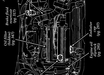
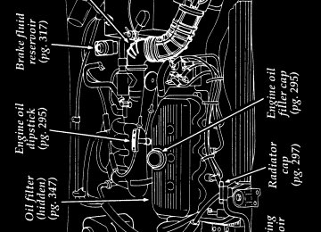
Brake fluid master cylinder reservoir
If the fluid is low, carefully clean and remove the filler cap from the reservoir. Fill the reservoir to the MAX line with Ford High Performance DOT 3 Brake Fluid C6AZ-19542-AA or DOT 3 equivalent fluid meeting Ford specification ESA-M6C25-A.
RWARNING
If you use a brake fluid that is not DOT 3, you will cause permanent damage to your brakes.
Do not fill the reservoir above the MAX line.
NOTE: Avoid spilling brake fluid on painted
surfaces.
If you find that the fluid level is excessively low — below the seam or ridge on the outside of the plastic reservoir — have the brake system inspected.
318
File:15ctsve.ex Update:Tue Sep 19 14:37:50 1995
*[SV31100(ALL)01/95]
%*[SV31200(ALL)02/95] *[SV31300(ALL)01/95]
%*[SV31400(ALL)03/95]
*[SV31500(ALL)02/95]
*[SV31600(ALL)01/95]
*[SV31700(ALL)05/95] [SV31850(ALL)02/94]
[SV32100(ALL)02/94]
[SV32150(ALL)03/95]
RWARNING
Do not let the reservoir for the master cylinder run dry. This may cause the brakes to fail.
Power Steering Fluid
Check the level of the power steering fluid at least twice a year (i.e., every Spring and Fall). Checking and Adding Power Steering Fluid
1. Start the engine and let it run until the
power steering fluid reaches normal operating temperature. The power steering fluid will be at the right temperature when the engine coolant temperature gauge in the instrument cluster is near the center of the NORMAL operating temperature range.
2. While the engine idles, turn the steering
wheel back and forth several times. Make sure that the cap assembly is installed at this time.
3. Turn the engine off.
4. Check the fluid level in the reservoir. The
fluid level should be in between the F (Full) and L (Low) markings on the reservoir.
5.
If the power steering fluid is low, add fluid in small amounts, continuously checking the level until you reach the F (Full) range. Do not overfill. To find out how much fluid your vehicle’s reservoir for the power steering fluid will hold, see Refill capacities in the Index.
6. When you are finished, put the reservoir cap
back on and make sure that it fits snugly.
319
File:15ctsve.ex Update:Tue Sep 19 14:37:50 1995
[SV32200(ALL)03/95]
*[SV32700(ALL)01/95]
%*[SV33000(ALL)04/95]
[SV33025(ALL)07/93]
[SV33050(ALL)07/93]
[SV33100(ALL)06/93]
Use only power steering fluid that meets Ford Specification ESW-M2C33-F, such as Motorcraft Type “F” Automatic Transmission and Power Steering Fluid.
If the power steering fluid is low, do not drive your vehicle for a long period of time before adding fluid. This can damage the power steering pump. Fuses, Fuse Links and Circuit Breakers Fuses, fuse links and circuit breakers protect your vehicle electrical system from overloading. If electrical parts in your vehicle are not working, the system may have been overloaded and blown a fuse, fuse link or tripped a circuit breaker. Before you replace or repair any electrical parts, check the appropriate circuit protector.
The following charts tell you which circuit protector protects each electrical part of your vehicle. If a fuse or fuse link blows, or a circuit breaker opens a circuit, none of the parts of your vehicle that use the circuit will work. For example, if the RADIO fuse is blown, the radio and remote control mirrors will not work. If the radio works, but the electric mirrors don’t work, something is wrong with the mirrors.
NOTE: Fuse links should only be repaired by
your dealer.
320
File:15ctsve.ex Update:Tue Sep 19 14:37:50 1995
*[SV33500(ALL)07/95] [SV33550(ALL)08/95]
[SV33555(ALL)08/95]
[SV33569(ALL)06/93]
[SV33570(ALL)08/95]
half page art:0000830-A
Fuses
If electrical parts in your vehicle are not working, the system may have been overloaded and blown a fuse. If a fuse blows, all the parts of your vehicle that use the fuse will not work.
Your vehicle has two fuse panels. The interior fuse panel is below the instrument panel in front of the driver’s door. The main panel is under the hood behind the battery.
The instrument panel fuse panel
Fuse panel under instrument panel
321
File:15ctsve.ex Update:Tue Sep 19 14:37:50 1995
[SV33575(ALL)08/95]
half page art:0070083-C
Inside of the instrument fuse panel cover
322
t
t
F
File:15ctsve.ex Update:Tue Sep 19 14:37:50 1995
[SV33742(ALL)06/93]
[SV33744(ALL)09/95]
half page art:0070085-D
The engine compartment fuse panel
Engine compartment fuse panel (1.8 liter)
326
File:15ctsve.ex Update:Tue Sep 19 14:37:50 1995
[SV33746(ALL)09/95]
half page art:0070086-D
Engine compartment fuse panel (1.9 liter)
327
F
F
t
File:15ctsve.ex Update:Tue Sep 19 14:37:50 1995
[SV33850(ALL)08/95]
[SV33900(ALL)09/95]
quarter page art:0030248-C
[SV33950(ALL)08/95]
[SV34000(ALL)08/95]
[SV34025(ALL)09/95]
[SV34050(ALL)08/95]
fourteen pica chart:0070082-B
To remove and replace a fuse, use the fuse puller tool provided.
RWARNING
Always replace a fuse with one that has the specified amperage rating. Using a fuse with a higher amperage rating can cause severe wire damage and could start a fire.
To find a fuse’s amperage rating, check the number on the fuse or check the color.
Color coding for fuses
331
File:15ctsve.ex Update:Tue Sep 19 14:37:50 1995
[SV34100(ALL)09/95]
%*[SV34300(ALL)03/95] [SV34425(ALL)08/95]
[SV34500(ALL)02/93]
[SV34550(ALL)02/93]
[SV34560(ALL)08/95]
six pica chart:0070011-B
*[SV34570(ALL)08/95]
Even after you replace a fuse, it will continue to blow if you do not find what caused the overload. If the fuse continues to blow, have your electrical system checked. Circuit Breakers
Circuit breakers open when a circuit overload exceeds their rated current (amperage). The manual reset-type used for the blower motor can be reset by pushing the red button located on top of the circuit breaker. If the overload which caused the circuit breaker to open is still present in the circuit, then the circuit breaker will open again and the red button will pop out. The overload must be removed from the circuit before proceeding.
The non-cycling type used for power seats, power windows, and power door locks will stay open once tripped until the overload is removed.
The circuit breaker chart
RWARNING
Always replace a fuse with one that has the specified amperage rating. Using a fuse with a higher amperage rating can cause severe wire damage and could start a fire.
332
File:15ctsve.ex Update:Tue Sep 19 14:37:50 1995
%*[SV37500(ALL)03/95] *[SV37600(ALL)01/95]
*[SV37700(ALL)01/95] *[SV37750(ALL)02/95] *[SV37800(ALL)01/95] *[SV37900(ALL)01/95] *[SV38000(ALL)01/95] *[SV38100(ALL)01/95] *[SV38200(ALL)01/95] *[SV38300(ALL)01/95] [SV38325(E )08/95] %*[SV38400(ALL)01/95]
*[SV38500(ALL)01/95]
*[SV38600(ALL)01/95]
*[SV38700(ALL)01/95]
Lights and Bulb Replacement It is a good idea to check the operation of the following lights frequently:
headlamps
high-mount brakelamp
tail lamps
brakelamps
hazard flasher
turn signals
side markers
license plate lamp
fog lamps (if equipped)
The alignment of your headlamps should be checked if:
oncoming motorists frequently signal you to turn off your vehicle’s high beams when you do not have the high beams on
the headlamps do not seem to give you enough light to see clearly at night
the headlamp beams are pointed substantially away from a position slightly down and to the right
333
File:15ctsve.ex Update:Tue Sep 19 14:37:50 1995
%*[SV38800(ALL)03/95] *[SV38900(ALL)01/95]
*[SV39000(ALL)05/95]
*[SV39100(ALL)01/95]
*[SV39300(ALL)03/95] *[SV39400(ALL)05/95]
*[SV39500(ALL)02/95]
[SV39550(ALL)09/89]
one third page art:0000831-A
Headlamp Bulb
The headlamps on your vehicle use replaceable bulbs. When the lamp burns out, simply replace the bulb, rather than the whole lamp.
RWARNING
Handle a halogen headlamp bulb carefully and keep out of children’s reach. Grasp the bulb only by its plastic base and do not touch the glass. The oil from your hand could cause the bulb to break the next time the headlamps are operated.
Do not remove the burned-out bulb unless you can immediately replace it with a new one. If a bulb is removed for an extended period of time, contaminants may enter the headlamp housing and affect its performance.
Removing the headlamp bulb
1. Make sure that the headlamp knob is in the
OFF position.
2. Lift the hood and find the bulb in the
headlamp socket.
Location of the headlamp bulb
334
File:15ctsve.ex Update:Tue Sep 19 14:37:50 1995
*[SV39801(ALL)02/95]
*[SV40001(ALL)02/95]
*[SV40300(ALL)03/95] *[SV40400(ALL)02/95]
*[SV40500(ALL)08/95]
*[SV40600(ALL)02/95]
*[SV40625(ALL)09/89]
3. Remove the electrical connector from the
bulb by pulling the connector.
4. Remove the bulb retaining ring by rotating it
counterclockwise (when viewed from the rear) about an eighth of a turn to free it from the bulb socket, and by sliding the ring off the plastic base. Keep the ring. It is to be used again to retain the new bulb.
Installing the headlamp bulb
1. With the flat side of the bulb’s plastic base facing upward, insert the glass end of the bulb into the socket. You may need to turn the bulb left or right to line up the grooves in the plastic base with the tabs in the socket. When the grooves are aligned, push the bulb into the socket until the plastic base contacts the rear of the socket.
2. Slip the bulb retaining ring over the plastic base until it contacts the rear of the socket. Lock the ring into the socket by rotating it clockwise until you feel a “stop.”
3. Push the electrical connector into the rear of the plastic base until it snaps, locking it into position.
4. Turn the headlamps on and make sure that
they work properly. If the headlamp was correctly aligned before you changed bulbs, you should not need to align it again.
335
File:15ctsve.ex Update:Tue Sep 19 14:37:50 1995
*[SV40650(ALL)01/95] [SV40655(ALL)08/95]
[SV40660(E )06/94]
half page art:0000832-A
[SV40665(ALL)09/89]
[SV40670(ALL)02/94]
[SV40675(ALL)09/89]
[SV40680(ALL)03/95]
[SV40685(ALL)09/89]
[SV40690(ALL)09/89]
High-Mount Brakelamp Bulb
Removing the brakelamp bulb
Location of the high-mount brakelamp (GT hatchback brakelamp is on spoiler)
1. Push in the center of each of the three mounting clips and pry each clip out.
2. Remove the high-mount brakelamp cover.
3. Remove the socket that contains the
burned-out bulb and replace the bulb.
Installing the brakelamp bulb
1. Push the bulb socket into the lamp assembly.
2. Secure the cover with the mounting clips.
336
File:15ctsve.ex Update:Tue Sep 19 14:37:50 1995
[SV40700(ALL)03/95]
[SV40710(ALL)08/93]
half page art:0070200-A
[SV40725(ALL)03/91]
[SV40750(ALL)03/91]
[SV40775(ALL)03/91]
[SV40800(ALL)03/91]
Replacing the brakelamp on a luggage compartment with spoiler
Location of the high-mount brakelamp on spoiler
1. Remove the two retaining screws and the
lens.
2. Detach the socket from the housing and
remove the bulb.
3. Replace the bulb and ease the socket back
into the housing.
4. Replace the lens and secure with the
retaining screws.
337
File:15ctsve.ex Update:Tue Sep 19 14:37:50 1995
[SV40820(ALL)03/95]
[SV40825(ALL)08/93]
half page art:0070201-A
[SV40830(ALL)08/93]
[SV40840(ALL)03/91]
[SV40850(ALL)03/91]
[SV40860(ALL)08/93]
Replacing a brakelamp mounted on the package tray in the rear window
Location of the high-mount brakelamp in rear window
1. Remove the two fastener clips and the
brakelamp assembly cover.
2. Detach the socket from the housing and
remove the bulb.
3. Replace the bulb and ease the socket back
into the housing.
4. Replace the brake assembly cover and secure
with the two fastener clips.
338
File:15ctsve.ex Update:Tue Sep 19 14:37:50 1995
*[SV40918(ALL)03/95] [SV40920(E )08/95]
Bulb Specifications
thirty-two pica chart:0070152-C
339
File:15ctsve.ex Update:Tue Sep 19 14:37:50 1995
[SV40930(E )08/95]
fourteen pica chart:0070027-C
%*[SV41000(ALL)03/95] *[SV41100(ALL)05/95]
*[SV41200(ALL)06/95]
Emission Control System Your vehicle is equipped with a catalytic converter which enables your vehicle to comply with applicable exhaust emission requirements.
RWARNING
Exhaust leaks may result in the entry of harmful and potentially lethal fumes into the passenger compartment. Under extreme conditions excessive exhaust temperatures could damage the fuel system, the interior floor covering, or other vehicle components, possibly causing a fire.
340
File:15ctsve.ex Update:Tue Sep 19 14:37:50 1995
*[SV41300(ALL)05/95]
*[SV41400(ALL)01/95] *[SV41500(ALL)01/95] *[SV41600(ALL)01/95]
*[SV41700(ALL)03/95]
*[SV41720(ALL)03/95]
*[SV41750(ALL)05/95]
To make sure that the catalytic converter and the other emission control parts continue to work properly: q Use only unleaded fuel. q Avoid running out of fuel. q Do not turn off the ignition while your
vehicle is moving, especially at high speeds.
q Have the services listed in the Maintenance
Schedule and Record booklet performed according to the specified schedule. The scheduled maintenance services are required because they are considered essential to the life and performance of your vehicle and to its emissions system.
In general, maintenance, replacement, or service of the emissions control devices or systems in your new Ford Motor Company vehicle or engine may be performed at your expense by any automotive repair establishment or individual using automotive parts equivalent to those which your vehicle or engine was originally equipped.
If other than Ford or Motorcraft or Ford authorized remanufactured parts are used for maintenance, replacement, or for the service of components affecting emissions control, the owner should be assured that such parts are warranted by their manufacturer to be equivalent to genuine Ford Motor Company parts in performance and durability. Please consult your warranty information booklet for complete warranty information.
341
File:15ctsve.ex Update:Tue Sep 19 14:37:50 1995
*[SV41800(ALL)05/95]
*[SV42000(ALL)01/95]
*[SV42100(ALL)01/95]
[SV42200(ALL)08/95]
*[SV42300(ALL)01/95]
%*[SV42400(ALL)05/95]
RWARNING
Do not park, idle, or drive your vehicle in dry grass or other dry ground cover. The emission system heats up the engine compartment and exhaust system, which can start a fire.
Do not make any unauthorized changes to your vehicle or engine. Changes that cause more unburned fuel to reach the exhaust system can increase the temperature of the engine or exhaust system.
By law, anyone who manufactures, repairs, services, sells, leases, trades vehicles, or supervises a fleet of vehicles is not permitted to intentionally remove an emission control device or prevent it from working. In some of the United States and in Canada, vehicle owners may be liable if their emission control device is removed or is prevented from working.
Never use a metal exhaust collector when you service your vehicle. If the metal collector contacts any of your vehicle’s plastic trim or bumper parts they could melt or deform.
Do not drive your vehicle if it does not operate properly. See your dealer if the engine runs on for more than five seconds after you shut it off or if it misfires, surges, stalls, or backfires.
Information about your vehicle’s emission control system is on the Vehicle Emission Control Information decal located on or near the engine. This decal identifies engine displacement and gives some tune-up specifications.
342
File:15ctsve.ex Update:Tue Sep 19 14:37:50 1995
%*[SV42405(ALL)07/95]
*[SV42410(ALL)07/95]
[SV42415(ALL)09/95]
[SV42416(ALL)08/95]
[SV42417(ALL)09/95]
Readiness for Inspection/Maintenance Testing
In some localities it may become a legal requirement to pass an Inspection/Maintenance (I/M) test of the On-Board Diagnostic (OBD) II system. If the vehicle’s powertrain system or its battery has just been serviced, the OBD II system is reset to a not ready for I/M testing condition. To prepare for I/M testing, the law specifies a “need for additional mixed city and highway driving to complete the check” of the OBD II system. As soon as all of the OBD II system checks are successfully completed, the OBD II system is set to the ready condition. The amount of driving required to reach the ready condition varies with individual driving patterns. To complete this requirement in the minimum amount of time, refer to the OBD II Drive Cycle defined below. If the vehicle owner cannot or does not want to do the additional driving required by law, a service center can perform this drive cycle as it would any other type of repair work. OBD II Drive Cycle (1.9L Engine only)
The following steps must be run in the order shown. If any steps are interrupted, repeat the preceding step. Any safe driving mode is acceptable between steps.
NOTE: Always drive vehicle in a safe manner
according to traffic conditions and obey all traffic laws.
343
File:15ctsve.ex Update:Tue Sep 19 14:37:50 1995
*[SV42420(ALL)07/95]
[SV42425(ALL)08/95]
[SV42430(ALL)08/95]
[SV42435(ALL)08/95]
[SV42440(ALL)08/95]
[SV42445(ALL)08/95]
[SV42450(ALL)08/95]
*[SV42455(ALL)07/95]
[SV42460(ALL)06/95]
*[SV42465(ALL)07/95]
[SV42470(ALL)08/95]
The engine must be warmed up and at operating temperature before proceeding with the drive modes of the following OBD II Drive Cycle.
1. Start the engine. Drive the vehicle or idle in
neutral for 4 minutes.
2.
Idle the vehicle in D (drive) (neutral for manual transaxles) for 40 seconds.
3. Accelerate the vehicle to 35 mph (55 km/h)
(manual transaxles upshift from 1st to 3rd gear) at 1/2 to 3/4 throttle for 10 seconds.
4. Drive the vehicle with a steady throttle at 35 mph (55 km/h) (manual transaxles use 3rd gear) for 30 seconds.
5.
Idle the vehicle in D (drive) (neutral for manual transaxles) for 40 seconds.
6. Continue to drive the vehicle in city traffic at
speeds between 25 and 40 mph (40-64 km/h) (manual transaxles primarily use 3rd and 4th gear when possible) for 15
minutes. During the 15 minute drive cycle the following modes must be achieved:a. at least 5 stop and idle modes at 10
seconds each
b. acceleration from idles at 1/2 to 3/4
throttle position, and
c. choose 3 different speeds to do 1.5
minute steady state throttle drives.7. Accelerate the vehicle up to between 45 and
60 mph (72-97 km/h) (manual transaxles upshift to 5th gear). This should take approximately 5 minutes.
344
File:15ctsve.ex Update:Tue Sep 19 14:37:50 1995
[SV42475(ALL)06/95]
[SV42480(ALL)06/95]
[SV42485(ALL)06/95]
*[SV42490(ALL)07/95]
*[SV42500(ALL)07/95]
%*[SV42600(ALL)07/95] [SV42650(ALL)06/94]
sixteen pica chart:0070029-I
8. Drive vehicle and hold the throttle steady at
the selected speed between 45 and 60 mph (72-97 km/h) for approximately 5 minutes.
9. Drive the vehicle for 5 minutes at varying
speeds between 45 and 60 mph (72-97 km/h).
10. Bring the vehicle back to idle. Idle in drive
for 40 seconds.
11. OBD II drive cycle has been completed.
Vehicle can be turned off when convenient. Refill Capacities, Motorcraft Parts, and Lubricant Specifications Refill Capacities
345
File:15ctsve.ex Update:Tue Sep 19 14:37:50 1995
[SV42700(ALL)05/94]
eighteen pica chart:0070028-I
346
File:15ctsve.ex Update:Tue Sep 19 14:37:50 1995
%*[SV42800(ALL)05/95] [SV42825(ALL)08/95]
Motorcraft Parts
eighteen pica chart:0070094-F
[SV42850(ALL)08/95]
If an original 1.9L engine spark plug is removed for examination, it must be reinstalled in the same cylinder. Spark plugs in cylinders 1 and 3
have a EG suffix. Spark plugs in cylinders 2 and 4 have a E suffix. If a spark plug needs to be replaced, use only spark plugs with the service part number suffix EE as shown on the engine decal.347
F
F
File:15ctsve.ex Update:Tue Sep 19 14:37:50 1995
%*[SV43100(ALL)01/95] *[SV43200(ALL)01/95] *[SV43300(ALL)01/95]
*[SV43400(ALL)01/95] *[SV43500(ALL)01/95] *[SV43600(ALL)01/95] *[SV43700(ALL)01/95]
*[SV43800(ALL)01/95] *[SV43900(ALL)01/95]
*[SV44000(ALL)01/95] *[SV44100(ALL)01/95] *[SV44200(ALL)01/95]
*[SV44300(ALL)04/95] *[SV44400(ALL)01/95] *[SV44500(ALL)01/95]
Vehicle Storage Maintenance Tips If you plan on storing your vehicle for an extended period of time (60 days or more), refer to the following maintenance recommendations to ensure your vehicle stays in good operating condition. General
Store all vehicles in a dry, ventilated place.
q Protect from sunlight, if possible.
If vehicles are stored outside, they require regular maintenance to protect against rust and damage.
Body q Wash vehicle thoroughly to remove dirt,
grease, oil, tar or mud from exterior surfaces, rear wheel housing and underside of front fenders.
q Periodically wash vehicles stored in exposed
locations.
q Touch-up raw or primed metal to prevent
rust.
q Cover chrome and stainless steel parts with a
thick coat of auto wax to prevent discoloration. Re-wax as necessary when the vehicle is washed.
q Lubricate all hood, door and trunk lid hinges
and latches with a light grade oil.
q Cover interior soft trim to prevent fading. q Keep all rubber parts free from oil and
solvents.
350
File:15ctsve.ex Update:Tue Sep 19 14:37:50 1995
%*[SV44600(ALL)01/95] *[SV44700(ALL)01/95] *[SV44800(ALL)01/95] %*[SV44900(ALL)01/95] %*[SV45000(ALL)07/94]
*[SV45200(ALL)03/95]
*[SV45300(ALL)01/95]
*[SV45400(ALL)01/95]
%*[SV45500(ALL)01/95] *[SV45600(ALL)01/95]
Engine
Start engine every 15 days. Run at fast idle until it reaches normal operating temperature. q With your foot on the brake, shift through all
the gears while the engine is running.
Fuel system
Fill fuel tank with high-quality unleaded fuel until the first automatic shutoff of the fuel pump nozzle.
NOTE: During extended periods of vehicle storage (60 days or more), fuel may deteriorate due to oxidation. This can damage rubber and other polymers in the fuel system and may also clog small orifices.
Ford Gas Stabilizer should be added whenever actual or expected storage periods exceed 60
days. Follow the instructions on the label. The vehicle should then be operated at idle speed to circulate the additive throughout the fuel system. A volatile corrosion inhibitor added to the fuel system will protect the fuel system’s inner surfaces from corrosion. Follow the instructions packaged with the product. Cooling system q Protect against freezing temperatures.351
File:15ctsve.ex Update:Tue Sep 19 14:37:50 1995
%*[SV45700(ALL)01/95] *[SV45800(ALL)01/95] *[SV45900(ALL)01/95] %*[SV46000(ALL)01/95] *[SV46100(ALL)01/95] %*[SV46200(ALL)01/95] *[SV46300(ALL)05/95] *[SV46400(ALL)01/95] *[SV46500(ALL)01/95]
*[SV46600(ALL)03/95]
Battery q Check and recharge as necessary. q Keep connections clean and covered with a
light coat of grease.
Brakes q Make sure brakes and parking brake are fully
released.
Tires q Maintain recommended air pressure. Miscellaneous q Make sure all linkages, cables, levers and clevis pins under vehicle are covered with grease to prevent rust.
q Move vehicles at least 25 feet (8 m) every 15
days to lubricate working parts and prevent corrosion.352
F
—
F