- 2015 Chevrolet Camaro Owners Manuals
- Chevrolet Camaro Owners Manuals
- 2000 Chevrolet Camaro Owners Manuals
- Chevrolet Camaro Owners Manuals
- 2014 Chevrolet Camaro Owners Manuals
- Chevrolet Camaro Owners Manuals
- 1993 Chevrolet Camaro Owners Manuals
- Chevrolet Camaro Owners Manuals
- 1999 Chevrolet Camaro Owners Manuals
- Chevrolet Camaro Owners Manuals
- 1996 Chevrolet Camaro Owners Manuals
- Chevrolet Camaro Owners Manuals
- 2012 Chevrolet Camaro Owners Manuals
- Chevrolet Camaro Owners Manuals
- 2016 Chevrolet Camaro Owners Manuals
- Chevrolet Camaro Owners Manuals
- 2001 Chevrolet Camaro Owners Manuals
- Chevrolet Camaro Owners Manuals
- 2011 Chevrolet Camaro Owners Manuals
- Chevrolet Camaro Owners Manuals
- 2010 Chevrolet Camaro Owners Manuals
- Chevrolet Camaro Owners Manuals
- 1994 Chevrolet Camaro Owners Manuals
- Chevrolet Camaro Owners Manuals
- 1995 Chevrolet Camaro Owners Manuals
- Chevrolet Camaro Owners Manuals
- 2002 Chevrolet Camaro Owners Manuals
- Chevrolet Camaro Owners Manuals
- 2013 Chevrolet Camaro Owners Manuals
- Chevrolet Camaro Owners Manuals
- 1998 Chevrolet Camaro Owners Manuals
- Chevrolet Camaro Owners Manuals
- 1997 Chevrolet Camaro Owners Manuals
- Chevrolet Camaro Owners Manuals
- Download PDF Manual
-
{ WARNING
Batteries have acid that can burn you and gas that can explode. You can be badly hurt if you are not careful. See Jump Starting on page 9-84 for tips on working around a battery without getting hurt.
Infrequent Usage: If the vehicle is driven infrequently, remove the black, negative (−) cable from the battery. This helps keep the battery from running down.
Extended Storage: For extended storage of the vehicle, remove the black, negative (−) cable from the battery or use a battery trickle charger. This helps maintain the charge of the battery over an extended period of time.
Rear Axle When to Check Lubricant It is not necessary to regularly check rear axle fluid unless you suspect there is a leak or you hear an unusual noise. A fluid loss could indicate a problem. Have it inspected and repaired.
How to Check Lubricant
V6 Automatic Transmission
shown, V6 Manual Transmission,
V8 Automatic and Manual
transmission similar
A. Fill Plug Hole B. Drain Plug Hole
To get an accurate reading, the vehicle should be on a level surface. If the level is below the bottom of the ï¬ller plug hole, add some lubricant. Add enough lubricant to raise the level to the bottom of the ï¬ller plug hole.
Starter Switch Check
{ WARNING When you are doing this inspection, the vehicle could move suddenly. If the vehicle moves, you or others could be injured.
1. Before starting this check,
be sure there is enough room around the vehicle.
2. Firmly apply both the parking brake and the regular brake. See Parking Brake on page 8-32. Do not use the accelerator pedal, and be ready to turn off the engine immediately if it starts.
Vehicle Care
9-31
3. For automatic transmission
vehicles, try to start the engine in each gear. The vehicle should start only in P (Park) or N (Neutral). If the vehicle starts in any other position, contact your dealer/retailer for service. For manual transmission vehicles, put the shift lever in Neutral, push the clutch pedal down halfway, and try to start the engine. The vehicle should start only when the clutch pedal is pushed down all the way to the floor. If the vehicle starts when the clutch pedal is not pushed all the way down, contact your dealer/retailer for service.
What to Use For 218 mm rear drive module (RDM) V6 manual, V8 automatic and V8 manual: To add lubricant when the level is low, use 75W-90 LS gear oil (GM Part No. US 89021677
and 1052358, in Canada Part No. 89021678 and 992694) meeting GM Speciï¬cation 9986226. To completely reï¬ll after draining, see Recommended Fluids and Lubricants on page 10-7. Then ï¬ll to the bottom of the ï¬ller plug hole with the Synthetic Gear Lubricant. For 195 mm RDM V6 automatic: To add lubricant when the level is low, use 75W-90 gear Oil (GM Part No. US 89021677, in Canada Part No. 89021678) meeting GM Speciï¬cation 9986115. To completely reï¬ll after draining, see Recommended Fluids and Lubricants on page 10-7. Then ï¬ll to the bottom of the ï¬ller plug hole with the Synthetic Gear Lubricant.9-32
Vehicle Care
Automatic Transmission Shift Lock Control System Check
{ WARNING When you are doing this inspection, the vehicle could move suddenly. If the vehicle moves, you or others could be injured.
1. Before starting this check, be
sure there is enough room around the vehicle. It should be parked on a level surface.
2. Firmly apply the parking brake.
See Parking Brake on page 8-32. Be ready to apply the regular brake immediately if the vehicle begins to move.
3. With the engine off, turn the ignition to ON/RUN, but do not start the engine. Without applying the regular brake, try to move the shift lever out of P (Park) with normal effort. If the shift lever moves out of P (Park), contact your dealer/retailer for service.
Ignition Transmission Lock Check While parked, and with the parking brake set, try to turn the ignition to LOCK/OFF in each shift lever position. • The ignition should turn to LOCK/OFF only when the shift lever is in P (Park).
• The ignition key should come out
only in LOCK/OFF.
Contact your dealer/retailer if service is required.
Park Brake and P (Park) Mechanism Check { WARNING
When you are doing this check, the vehicle could begin to move. You or others could be injured and property could be damaged. Make sure there is room in front of the vehicle in case it begins to roll. Be ready to apply the regular brake at once should the vehicle begin to move.
Wiper Blade Replacement Windshield wiper blades should be inspected for wear and cracking. See Scheduled Maintenance on page 10-2 for more information. Replacement blades come in different types and are removed in different ways. For proper type and length, see Maintenance Replacement Parts on page 10-9.
Park on a fairly steep hill, with the vehicle facing downhill. Keeping your foot on the regular brake, set the parking brake. • To check the parking brake’s
holding ability: With the engine running and the transmission in N (Neutral), slowly remove foot pressure from the regular brake pedal. Do this until the vehicle is held by the parking brake only.
• To check the P (Park)
mechanism’s holding ability: With the engine running, shift to P (Park). Then release the parking brake followed by the regular brake.
Contact your dealer/retailer if service is required.
Vehicle Care
9-33
To replace the windshield wiper blade: 1. Pull the windshield wiper assembly away from the windshield.
2. Lift up on the latch in the middle
of the wiper blade where the wiper arm attaches.
9-34
Vehicle Care
3. With the latch open, pull the
wiper blade down towards the windshield far enough to release it from the J-hooked end of the wiper arm.
4. Remove the wiper blade.
Allowing the wiper blade arm to touch the windshield when no wiper blade is installed could damage the windshield. Any damage that occurs would not be covered by the vehicle warranty. Do not allow the wiper blade arm to touch the windshield.
5. Reverse steps 1 through 3 for
wiper blade replacement.
Headlamp Aiming The headlamp aiming system has been preset at the factory. If the vehicle is damaged in an accident, the aim of the headlamps may be affected and adjustment may be necessary. It is recommended that a dealer/retailer adjust the headlamps. To re-aim the headlamps yourself, use the following procedure. The vehicle should be properly prepared as follows: • The vehicle should be placed so the headlamps are 7.6 m (25 ft) from a light colored wall.
• The vehicle must have all four tires on a level surface which is level all the way to the wall.
• The vehicle should be placed so it is perpendicular to the wall or other flat surface.
• The vehicle should not have any
snow, ice, or mud on it.
• The vehicle should be fully
assembled and all other work stopped while headlamp aiming is being performed.
• The vehicle should be normally loaded with a full tank of fuel and one person or 75 kg (160 lbs) sitting on the driver’s seat.
• Tires should be properly inflated. Headlamp aiming is done with the vehicle’s low-beam headlamps. The high-beam headlamps will be correctly aimed if the low-beam headlamps are aimed properly.
To adjust the vertical aim: 1. Open the hood. See Hood on page 9-5 for more information.
Vehicle Care
9-35
Halogen Headlamp
HID Headlamp
2. Locate the aim dot on the lens of
the low-beam headlamp.
3. Measure the distance from the
ground to the aim dot on the low-beam headlamp. Record the distance.
4. At the wall measure from
the ground upward (A) to the recorded distance from Step 3
and mark it.5. Draw or tape a horizontal line (B)
on the wall the width of the vehicle at the height of the mark in Step 4.
9-36
Vehicle Care
Notice: Do not cover a headlamp to improve beam cut-off when aiming. Covering a headlamp may cause excessive heat build-up which may cause damage to the headlamp. 6. Turn on the low-beam
headlamps and place a piece of cardboard or equivalent in front of the headlamp not being adjusted. This allows only the beam of light from the headlamp being adjusted to be seen on the flat surface.
Halogen Headlamp
HID Headlamp
7. Locate the vertical headlamp
aiming screws, which are under the hood near each headlamp assembly. The adjustment screw can be turned with a 6 mm hex key.
8. Turn the vertical aiming screw
until the headlamp beam is aimed to the horizontal tape line. Turn it clockwise or counterclockwise to raise or lower the angle of the beam.
9. Make sure that the light from the headlamp is positioned at the bottom edge of the horizontal tape line. The lamp on the left (A) shows the correct headlamp aim. The lamp on the right (B) shows the incorrect headlamp aim.
10. Repeat Steps 6 through 9 for
the opposite headlamp.
Bulb Replacement For the proper type of replacement bulbs, see Replacement Bulbs on page 9-41. For any bulb changing procedure not listed in this section, contact your dealer/retailer.
Halogen Bulbs
{ WARNING
Halogen bulbs have pressurized gas inside and can burst if you drop or scratch the bulb. You or others could be injured. Be sure to read and follow the instructions on the bulb package.
High Intensity Discharge (HID) Lighting
{ WARNING
The low beam high intensity discharge lighting system operates at a very high voltage. If you try to service any of the system components, you could be seriously injured. Have your dealer/retailer or a qualiï¬ed technician service them.
The up–level vehicle is equipped with HID headlamps. The park lamp function is also a function of the HID headlamp. After an HID headlamp bulb has been replaced, you may notice that the beam is a slightly different shade than it was originally. This is normal.
Vehicle Care
9-37
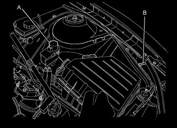
Headlamps, Front Turn Signal and Parking Lamps (Base Vehicle) The base model vehicle has a halogen headlamp and a turn signal/parking lamp on the headlamp assembly. To replace one of these bulbs: 1. Open the hood. See Hood on
page 9-5.
2. Press in on the tabs located on
the sides of the duct and then push the duct rearward into the air cleaner/ï¬lter housing.
9-38
Vehicle Care
A. Parking/Turn Signal Lamp B. Halogen Headlamp
3. Disconnect the wiring harness
and turn the bulb socket counterclockwise to remove it from the headlamp assembly.
4. Pull the bulb straight out from the
socket.
5. Push the new bulb into the
socket and reinstall the socket into the headlamp assembly by turning it clockwise.
6. Reconnect the electrical
connector.
7. Pull the duct back out of the air cleaner/ï¬lter housing until the tabs snap the duct back into position.
Headlamps, Front Turn Signal and Parking Lamps (Up-Level Vehicle) The up–level model vehicle has a HID headlamp and a turn signal lamp on the headlamp assembly. The park lamp is also the function of the HID headlamp. See High Intensity Discharge (HID) Lighting on page 9-37 for more information.
To replace the turn signal bulb: 1. Open the hood. See Hood
on page 9-5.
2. Press in on the tabs located on
the sides of the duct and then push the duct rearward into the air cleaner/ï¬lter housing.
Daytime Running Lamps (DRL) The up-level model vehicle may have daytime running lamps which would be located on the facia. To replace one of these bulbs:
Vehicle Care
9-39
3. Push in the new bulb assembly
to lock it into place.
4. Reconnect the electrical
connector to the bulb assembly.
The base model vehicle daytime running lamps are the low beam on the halogen headlamp. If one these lamps fail, see Headlamps, Front Turn Signal and Parking Lamps (Base Vehicle) on page 9-37
or Headlamps, Front Turn Signal and Parking Lamps (Up-Level Vehicle) on page 9-38 for replacement information.1. Locate the bulb assembly under
the front facia.
2. Disconnect the electrical connector from the bulb assembly and pull out the bulb assembly.
3. Disconnect the wiring harness
and turn the bulb socket counterclockwise to remove it from the headlamp assembly.
4. Pull the bulb straight out from the
socket.
5. Push the new bulb into the
socket and reinstall the socket into the headlamp assembly by turning it clockwise.
6. Reconnect the electrical
connector.
7. Pull the duct back out of the air cleaner/ï¬lter housing until the tabs snap the duct back into position.
9-40
Vehicle Care
Fog Lamps The base model vehicle may have fog lamps which would be located on the facia. To replace one of these bulbs:
The up-level vehicle will not be equipped with fog lamps.
Taillamps, Turn Signal, and Stoplamps To replace a taillamp, turn signal, or stoplamp bulb: 1. Open the trunk. See Trunk on
page 1-8.
4. Pull the old bulb straight out of
the bulb socket.
5. Push the new bulb straight into
the bulb socket until it clicks.
6. Turn the bulb socket clockwise to
reinstall.
License Plate Lamp To replace one of these bulbs:
1. Locate the bulb assembly under
the front facia.
2. Disconnect the electrical connector from the bulb assembly and pull out the bulb assembly.
3. Push in the new bulb assembly
to lock it into place.
4. Reconnect the electrical
connector to the bulb assembly.
2. Remove the close out panel
retainers to gain access to the bulb socket connectors.
3. Turn the bulb socket
counterclockwise to remove it.
1. Unclip the license plate lamp
from the facia opening.
2. Pull the license plate lamp down
through the facia opening.
3. Turn the bulb socket
counterclockwise and pull the bulb straight out of the lamp socket.
4. Install the new bulb. 5. Push the bulb straight into the
socket and turn clockwise to reinstall.
6. Reinstall the license plate lamp
by lifting it through the facia opening until the clip is in place.
Replacement Bulbs
Exterior Lamp
Daytime Running Lamp (Up-level vehicles) Fog Lamp Front Park and Turn Signal Lamp Halogen Headlamp License Plate Lamp Rear Turn Signal and Taillamps
Bulb
Number
P13W
PS24W
3457NAK
H13
W5W3157K
For replacement bulbs not listed here, contact your dealer/retailer.
Vehicle Care
9-41
Electrical System Electrical System Overload The vehicle has fuses and circuit breakers to protect against an electrical system overload. When the current electrical load is too heavy, the circuit breaker opens and closes, protecting the circuit until the current load returns to normal or the problem is ï¬xed. This greatly reduces the chance of circuit overload and ï¬re caused by electrical problems. Fuses and circuit breakers protect the following in the vehicle: • Headlamp Wiring • Windshield Wiper Motor • Power Windows and other Power
Accessories
9-42
Vehicle Care
Headlamp Wiring An electrical overload may cause the lamps to go on and off, or in some cases to remain off. Have the headlamp wiring checked right away if the lamps go on and off or remain off.
Windshield Wipers If the wiper motor overheats due to heavy snow or ice, the windshield wipers will stop until the motor cools and will then restart. Although the circuit is protected from electrical overload, overload due to heavy snow or ice, may cause wiper linkage damage. Always clear ice and heavy snow from the windshield before using the windshield wipers. If the overload is caused by an electrical problem and not snow or ice, be sure to get it ï¬xed.
Fuses and Circuit Breakers The wiring circuits in the vehicle are protected from short circuits by a combination of fuses and circuit breakers. This greatly reduces the chance of damage caused by electrical problems. To check a fuse, look at the silver-colored band inside the fuse. If the band is broken or melted, replace the fuse. Be sure to replace a bad fuse with a new one of the identical size and rating. Fuses of the same amperage can be temporarily borrowed from another fuse location, if a fuse goes out. Replace the fuse as soon as possible. To identify and check fuses, circuit breakers, and relays, see Engine Compartment Fuse Block on page 9-42, Instrument Panel Fuse Block on page 9-45, and Rear Compartment Fuse Block on page 9-46.
Engine Compartment Fuse Block
To remove the hinged fuse block cover, press the clip at the front of the cover, and swing it up. Notice: Spilling liquid on any electrical components on the vehicle may damage it. Always keep the covers on any electrical component.
Vehicle Care
9-43
J-Case Fuses
41
42
43
44
Usage
Cooling Fan High Front Heater, Ventilation and Air Conditioning Antilock Brake System Pump Cooling Fan Low
Mini Fuses
Usage
10
Air Conditioning Compressor Clutch Transmission Control Module Engine Control Module Main Pre-Catalytic Converter Oxygen Sensor Post-Catalytic Converter Oxygen Sensor Fuel Injectors – Even Fuel Injectors – Odd
Engine Compartment Fuse Block
J-Case Fuses
12
22
Usage
Wiper Starter Brake Vacuum Pump
J-Case Fuses
25
26
27
Usage
Power Windows Rear Power Windows Front Rear Defog
9-44
Vehicle Care
Mini Fuses
Usage
Mini Fuses
Usage
11
14
15
1617
18
19
20
31
32
33
Cooling Fan Relay Manifold Air Flow/Chassis Control Ignition Run/Crank IP Sensing Diagnostic Module/Ignition Run/Crank Body Transmission Control Module/ Ignition Engine Control Module/Ignition Outside Rear View Mirror Canister Vent Solenoid Body Control Module #6
34
35
3840
46
47
50
51
5255
56
61
Sunroof Front Heated Seats Washer Pump Front Antilock Brake System Valves HID Headlamp – Left Front HID Headlamp – Right Front Fog Lamps Horn Spare High Beam Headlamp – Right Front High Beam Headlamp – Left Front Heated Mirror
Mini
Relays
K26
K50
K55
K612
K614Micro Relays
K61
K69
K613K617
K619
K627
K632
Usage
Powertrain Run / Crank Rear Defog Cooling Fan High Cooling Fan Control
Usage
Starter Wiper Control Cooling Fan Low Air Conditioning Compressor Clutch Wiper Speed High Intensity Discharge Headlamps Brake Vacuum Pump
Instrument Panel Fuse Block
Vehicle Care
9-45
The instrument panel fuse block is located on the end of the instrument panel, on the driver side of the vehicle. To access the fuses, open the fuse panel door by pulling out. To reinstall the door, push the door back into its original location.
Instrument Panel Fuse Block
Fuses
F1
F2
F3
F4Usage Discrete Logic Ignition Switch Diagnostic Link Connector Airbag Cluster
Fuses
Usage
F5
F6
F8
F9Heating Ventilation Air Conditioning Controller Body Control Module Battery Spare
9-46
Vehicle Care
Usage
Fuses
Fuses F10
F11
F12
F13F14
F15
F16
F17
F18F19
F20
F21
F22
F23F24
Spare Spare Spare Display OnStar® Universal Hands Free Phone Body Control Module 3
Body Control Module 4
Power Outlet 1
Power Outlet 2
Steering Wheel Controls Backlight Spare Spare Spare Trunk Automatic Occupant SensingRear Compartment Fuse Block
Usage Body Control Module 1
Body Control Module 8
Spare Body Control Module 5
Body Control Module 7F25
F27
F28
F29
F30
Circuit Breakers
CB7
CB26Usage
Passenger Seat Driver Seat
Relays
Usage
K10
K605
K609Retained Accessory Power Not Used Trunk
The rear compartment fuse block is located on the right side of the trunk behind a cover. Remove the six convenience net retainers, the rear sill plate, and the two passenger side trim retainers, then swing the trim out of the way.
Vehicle Care
9-47
Fuses
Usage
F9
F10
F11
F12F13
F14
F15
F16
Spare Spare Spare Spare Engine Control Module/Battery Regulated Voltage Control Fuel System Control Module Spare
Fuses
Usage
Fuses
Usage
Universal Garage Door Opener/ Ultrasonic Reverse Parking Aid Ampliï¬er Radio
F1
F2
F3F4
F5
F6
F7
F8Spare Convertible Top 1
Convertible Top 2
Spare Spare9-48
Vehicle Care
Wheels and Tires Tires Your new vehicle comes with high-quality tires made by a leading tire manufacturer. If you ever have questions about your tire warranty and where to obtain service, see your vehicle Warranty booklet for details. For additional information refer to the tire manufacturer. { WARNING
Poorly maintained and improperly used tires are dangerous.
• Overloading your tires can
cause overheating as a result of too much flexing. You could have an air-out and a serious accident. See Vehicle Load Limits on page 8-12.
(Continued)
WARNING (Continued)
• Underinflated tires pose the same danger as overloaded tires. The resulting accident could cause serious injury. Check all tires frequently to maintain the recommended pressure. Tire pressure should be checked when your tires are cold. See Tire Pressure on page 9-54.
• Overinflated tires are more likely to be cut, punctured or broken by a sudden impact — such as when you hit a pothole. Keep tires at the recommended pressure.
• Worn, old tires can cause accidents. If your tread is badly worn, or if your tires have been damaged, replace them.
Winter Tires If you expect to drive on snow or ice covered roads often, you may want to get winter tires for your vehicle. All season tires provide good overall performance on most surfaces but they may not offer the traction you would like or the same level of performance as winter tires on snow or ice covered roads. Winter tires, in general, are designed for increased traction on snow and ice covered roads. With winter tires, there may be decreased dry road traction, increased road noise, and shorter tread life. After switching to winter tires, be alert for changes in vehicle handling and braking. See your dealer/retailer for details regarding winter tire availability and proper tire selection. Also, see Buying New Tires on page 9-63.
If you choose to use winter tires: • Use tires of the same brand and
tread type on all four wheel positions.
• Use only radial ply tires of the
same size, load range, and speed rating as the original equipment tires.
Winter tires with the same speed rating as your original equipment tires may not be available for H, V, W, Y, and ZR speed rated tires. If you choose winter tires with a lower speed rating, never exceed the tire’s maximum speed capability.
Tire Sidewall Labeling Useful information about a tire is molded into its sidewall. The examples below show a typical passenger vehicle tire and a compact spare tire sidewall.
Passenger (P-Metric)
Tire Example
(A) Tire Size: The tire size is a combination of letters and numbers used to deï¬ne a particular tire’s width, height, aspect ratio, construction type, and service description. See the “Tire Size†illustration later in this section for more detail.
Vehicle Care
9-49
(B) TPC Spec (Tire Performance Criteria Speciï¬cation): Original equipment tires designed to GM’s speciï¬c tire performance criteria have a TPC speciï¬cation code molded onto the sidewall. GM’s TPC speciï¬cations meet or exceed all federal safety guidelines. (C) DOT (Department of Transportation): The Department of Transportation (DOT) code indicates that the tire is in compliance with the U.S. Department of Transportation Motor Vehicle Safety Standards.
9-50
Vehicle Care
(D) Tire Identiï¬cation Number (TIN): The letters and numbers following the DOT (Department of Transportation) code is the Tire Identiï¬cation Number (TIN). The TIN shows the manufacturer and plant code, tire size, and date the tire was manufactured. The TIN is molded onto both sides of the tire, although only one side may have the date of manufacture. (E) Tire Ply Material: The type of cord and number of plies in the sidewall and under the tread. (F) Uniform Tire Quality Grading (UTQG): Tire manufacturers are required to grade tires based on three performance factors: treadwear, traction, and temperature resistance. For more information see Uniform Tire Quality Grading on page 9-65.
(G) Maximum Cold Inflation Load Limit: Maximum load that can be carried and the maximum pressure needed to support that load.
Compact Spare Tire Example
(A) Tire Ply Material: The type of cord and number of plies in the sidewall and under the tread. (B) Temporary Use Only: The compact spare tire or temporary use tire has a tread life of approximately 3,000 miles (5 000 km) and should not be
driven at speeds over 65 mph (105 km/h). The compact spare tire is for emergency use when a regular road tire has lost air and gone flat. If your vehicle has a compact spare tire, see Compact Spare Tire on page 9-83 and If a Tire Goes Flat on page 9-69. (C) Tire Identiï¬cation Number (TIN): The letters and numbers following the DOT (Department of Transportation) code is the Tire Identiï¬cation Number (TIN). The TIN shows the manufacturer and plant code, tire size, and date the tire was manufactured. The TIN is molded onto both sides of the tire, although only one side may have the date of manufacture. (D) Maximum Cold Inflation Load Limit: Maximum load that can be carried and the maximum pressure needed to support that load.
(E) Tire Inflation: The temporary use tire or compact spare tire should be inflated to 60 psi (420 kPa). For more information on tire pressure and inflation see Tire Pressure on page 9-54. (F) Tire Size : A combination of letters and numbers deï¬ne a tire’s width, height, aspect ratio, construction type, and service description. The letter T as the ï¬rst character in the tire size means the tire is for temporary use only. (G) TPC Spec (Tire Performance Criteria Speciï¬cation): Original equipment tires designed to GM’s speciï¬c tire performance criteria have a TPC speciï¬cation code molded onto the sidewall. GM’s TPC speciï¬cations meet or exceed all federal safety guidelines.
Tire Designations Tire Size The following illustration shows an example of a typical passenger vehicle tire size.
(A) Passenger (P-Metric) Tire: The United States version of a metric tire sizing system. The letter P as the ï¬rst character in the tire size means a passenger vehicle tire engineered to standards set by the U.S. Tire and Rim Association. (B) Tire Width: The three-digit number indicates the tire section width in millimeters from sidewall to sidewall.
Vehicle Care
9-51
(C) Aspect Ratio: A two-digit number that indicates the tire height-to-width measurements. For example, if the tire size aspect ratio is 60, as shown in item C of the illustration, it would mean that the tire’s sidewall is 60 percent as high as it is wide. (D) Construction Code: A letter code is used to indicate the type of ply construction in the tire. The letter R means radial ply construction; the letter D means diagonal or bias ply construction; and the letter B means belted-bias ply construction. (E) Rim Diameter: Diameter of the wheel in inches. (F) Service Description: These characters represent the load index and speed rating of the tire. The load index represents the load carry capacity a tire is certiï¬ed to carry. The speed rating is the maximum speed a tire is certiï¬ed to carry a load.
9-52
Vehicle Care
Tire Terminology and Deï¬nitions Air Pressure: The amount of air inside the tire pressing outward on each square inch of the tire. Air pressure is expressed in pounds per square inch (psi) or kilopascal (kPa). Accessory Weight: This means the combined weight of optional accessories. Some examples of optional accessories are, automatic transmission, power steering, power brakes, power windows, power seats, and air conditioning. Aspect Ratio: The relationship of a tire’s height to its width. Belt: A rubber coated layer of cords that is located between the plies and the tread. Cords may be made from steel or other reinforcing materials.
Bead: The tire bead contains steel wires wrapped by steel cords that hold the tire onto the rim. Bias Ply Tire: A pneumatic tire in which the plies are laid at alternate angles less than 90 degrees to the centerline of the tread. Cold Tire Pressure: The amount of air pressure in a tire, measured in pounds per square inch (psi) or kilopascals (kPa) before a tire has built up heat from driving. See Tire Pressure on page 9-54. Curb Weight: The weight of a motor vehicle with standard and optional equipment including the maximum capacity of fuel, oil, and coolant, but without passengers and cargo.
DOT Markings: A code molded into the sidewall of a tire signifying that the tire is in compliance with the U.S. Department of Transportation (DOT) motor vehicle safety standards. The DOT code includes the Tire Identiï¬cation Number (TIN), an alphanumeric designator which can also identify the tire manufacturer, production plant, brand, and date of production. GVWR: Gross Vehicle Weight Rating. See Vehicle Load Limits on page 8-12. GAWR FRT: Gross Axle Weight Rating for the front axle. See Vehicle Load Limits on page 8-12. GAWR RR: Gross Axle Weight Rating for the rear axle. See Vehicle Load Limits on page 8-12.
Intended Outboard Sidewall: The side of an asymmetrical tire, that must always face outward when mounted on a vehicle. Kilopascal (kPa): The metric unit for air pressure. Light Truck (LT-Metric) Tire: A tire used on light duty trucks and some multipurpose passenger vehicles. Load Index: An assigned number ranging from 1 to 279
that corresponds to the load carrying capacity of a tire. Maximum Inflation Pressure: The maximum air pressure to which a cold tire can be inflated. The maximum air pressure is molded onto the sidewall. Maximum Load Rating: The load rating for a tire at the maximum permissible inflation pressure for that tire.Maximum Loaded Vehicle Weight: The sum of curb weight, accessory weight, vehicle capacity weight, and production options weight. Normal Occupant Weight: The number of occupants a vehicle is designed to seat multiplied by 150 lbs (68 kg). See Vehicle Load Limits on page 8-12. Occupant Distribution: Designated seating positions. Outward Facing Sidewall: The side of an asymmetrical tire that has a particular side that faces outward when mounted on a vehicle. The side of the tire that contains a whitewall, bears white lettering, or bears manufacturer, brand, and/or model name molding that is higher or deeper than the same moldings on the other sidewall of the tire.
Vehicle Care
9-53
Passenger (P-Metric) Tire: A tire used on passenger cars and some light duty trucks and multipurpose vehicles. Recommended Inflation Pressure: Vehicle manufacturer’s recommended tire inflation pressure as shown on the tire placard. See Tire Pressure on page 9-54 and Vehicle Load Limits on page 8-12. Radial Ply Tire: A pneumatic tire in which the ply cords that extend to the beads are laid at 90 degrees to the centerline of the tread. Rim: A metal support for a tire and upon which the tire beads are seated. Sidewall: The portion of a tire between the tread and the bead.
9-54
Vehicle Care
Speed Rating: An alphanumeric code assigned to a tire indicating the maximum speed at which a tire can operate. Traction: The friction between the tire and the road surface. The amount of grip provided. Tread: The portion of a tire that comes into contact with the road. Treadwear Indicators: Narrow bands, sometimes called wear bars, that show across the tread of a tire when only 1/16 inch (1.6 mm) of tread remains. See When It Is Time for New Tires on page 9-62. UTQGS (Uniform Tire Quality Grading Standards): A tire information system that provides consumers with ratings for a tire’s traction, temperature, and treadwear. Ratings are determined by tire manufacturers using government testing
procedures. The ratings are molded into the sidewall of the tire. See Uniform Tire Quality Grading on page 9-65. Vehicle Capacity Weight: The number of designated seating positions multiplied by 150 lbs (68 kg) plus the rated cargo load. See Vehicle Load Limits on page 8-12. Vehicle Maximum Load on the Tire: Load on an individual tire due to curb weight, accessory weight, occupant weight, and cargo weight. Vehicle Placard: A label permanently attached to a vehicle showing the vehicle’s capacity weight and the original equipment tire size and recommended inflation pressure. See “Tire and Loading Information Label†under Vehicle Load Limits on page 8-12.
Tire Pressure Tires need the correct amount of air pressure to operate effectively. Notice: Do not let anyone tell you that under-inflation or over-inflation is all right. It is not. If your tires do not have enough air (under-inflation), you can get the following: (cid:129) Too much flexing (cid:129) Too much heat (cid:129) Tire overloading (cid:129) Premature or irregular wear (cid:129) Poor handling (cid:129) Reduced fuel economy If your tires have too much air (over-inflation), you can get the following: (cid:129) Unusual wear (cid:129) Poor handling (cid:129) Rough ride (cid:129) Needless damage from road
hazards
A vehicle speciï¬c Tire and Loading Information label is attached to your vehicle. This label shows your vehicle’s original equipment tires and the correct inflation pressures for your tires when they are cold. The recommended cold tire inflation pressure, shown on the label, is the minimum amount of air pressure needed to support your vehicle’s maximum load carrying capacity. For additional information regarding how much weight your vehicle can carry, and an example of the Tire and Loading Information label, see Vehicle Load Limits on page 8-12. How you load your vehicle affects vehicle handling and ride comfort. Never load your vehicle with more weight than it was designed to carry.
When to Check Check your tires once a month or more. Do not forget to check the compact spare tire, if the vehicle has one. The compact spare should be at 60 psi (420 kPa). For additional information regarding the compact spare tire, see Compact Spare Tire on page 9-83. How to Check Use a good quality pocket-type gage to check tire pressure. You cannot tell if your tires are properly inflated simply by looking at them. Radial tires may look properly inflated even when they are under-inflated. Check the tire’s inflation pressure when the tires are cold. Cold means your vehicle has been sitting for at least three hours or driven no more than 1 mile (1.6 km).
Vehicle Care
9-55
Remove the valve cap from the tire valve stem. Press the tire gage ï¬rmly onto the valve to get a pressure measurement. If the cold tire inflation pressure matches the recommended pressure on the Tire and Loading Information label, no further adjustment is necessary. If the inflation pressure is low, add air until you reach the recommended amount. If you overï¬ll the tire, release air by pushing on the metal stem in the center of the tire valve. Re-check the tire pressure with the tire gage. Be sure to put the valve caps back on the valve stems. They help prevent leaks by keeping out dirt and moisture.
9-56
Vehicle Care
Tire Pressure for High-Speed Operation
{ WARNING
Driving at high speeds, 100 mph (160 km/h) or higher, puts an additional strain on tires. Sustained high-speed driving causes excessive heat build up and can cause sudden tire failure. You could have a crash and you or others could be killed. Some high-speed rated tires require inflation pressure adjustment for high speed operation. When speed limits and road conditions are such that a vehicle can be driven at high speeds, make sure the tires are rated for high speed operation, in excellent condition, and set to the correct cold tire inflation pressure for the vehicle load.
Vehicles with 245/45ZR20 103Y, P245/50ZR19 104W and 275/40ZR20 106Y size tires, have tires capable of high speed use. Make sure the tires are inflated to the recommended cold inflation pressures before operating the vehicle at speeds over 100 mph (160 km/h). See Vehicle Load Limits on page 8-12 and Tire Pressure on page 9-54.
Tire Pressure Monitor System The Tire Pressure Monitor System (TPMS) uses radio and sensor technology to check tire pressure levels. The TPMS sensors monitor the air pressure in your vehicle’s tires and transmit tire pressure readings to a receiver located in the vehicle. Each tire, including the spare (if provided), should be checked monthly when cold and inflated to the inflation pressure recommended by the vehicle manufacturer on the
vehicle placard or tire inflation pressure label. (If your vehicle has tires of a different size than the size indicated on the vehicle placard or tire inflation pressure label, you should determine the proper tire inflation pressure for those tires.) As an added safety feature, your vehicle has been equipped with a tire pressure monitoring system (TPMS) that illuminates a low tire pressure telltale when one or more of your tires is signiï¬cantly under-inflated. Accordingly, when the low tire pressure telltale illuminates, you should stop and check your tires as soon as possible, and inflate them to the proper pressure. Driving on a signiï¬cantly under-inflated tire causes the tire to overheat and can lead to tire failure. Under-inflation also reduces fuel efficiency and tire tread life, and may affect the vehicle’s handling and stopping ability.
Please note that the TPMS is not a substitute for proper tire maintenance, and it is the driver’s responsibility to maintain correct tire pressure, even if under-inflation has not reached the level to trigger illumination of the TPMS low tire pressure telltale. Your vehicle has also been equipped with a TPMS malfunction indicator to indicate when the system is not operating properly. The TPMS malfunction indicator is combined with the low tire pressure telltale. When the system detects a malfunction, the telltale will flash for approximately one minute and then remain continuously illuminated. This sequence will continue upon subsequent vehicle start-ups as long as the malfunction exists. When the malfunction indicator is illuminated, the system may not be able to detect or signal low tire pressure as intended. TPMS malfunctions may occur for a variety
of reasons, including the installation of replacement or alternate tires or wheels on the vehicle that prevent the TPMS from functioning properly. Always check the TPMS malfunction telltale after replacing one or more tires or wheels on your vehicle to ensure that the replacement or alternate tires and wheels allow the TPMS to continue to function properly. See Tire Pressure Monitor Operation on page 9-57 for additional information. Federal Communications Commission (FCC) and Industry and Science Canada See Radio Frequency Statement (US, Can) on page 12-15 for information regarding Part 15
of the Federal Communications Commission (FCC) Rules and RSS-210/211 of Industry and Science Canada.Vehicle Care
9-57
Tire Pressure Monitor Operation This vehicle may have a Tire Pressure Monitor System (TPMS). The TPMS is designed to warn the driver when a low tire pressure condition exists. TPMS sensors are mounted onto each tire and wheel assembly, excluding the spare tire and wheel assembly, if the vehicle has one. The TPMS sensors monitor the air pressure in the vehicle’s tires and transmits the tire pressure readings to a receiver located in the vehicle. Using the Driver Information Center (DIC), the driver can also check tire pressure levels using the DIC. For additional information and details about the DIC operation and displays see Tire Messages on page 4-36.
9-58
Vehicle Care
When a low tire pressure condition is detected, the TPMS illuminates the low tire pressure warning light located on the instrument panel cluster. A DIC warning message to check the pressure in a speciï¬c tire is also shown on the DIC display screen. The low tire pressure warning light and the DIC warning message come at each ignition cycle until the tires are inflated to the correct inflation pressure.
The low tire pressure warning light may come on in cool weather when the vehicle is ï¬rst started, and then turn off as you start to drive. This could be an early indicator that the air pressure in the tire(s) are getting low and need to be inflated to the proper pressure. The Tire and Loading Information label, attached to your vehicle, shows the size of your vehicle’s original equipment tires and the correct inflation pressure for the tires when they are cold. See Vehicle Load Limits on page 8-12, for an example of the Tire and Loading Information label and its location on your vehicle. Also see Tire Pressure on page 9-54. Your vehicle’s TPMS can warn you about a low tire pressure condition but it does not replace normal tire
maintenance. See Tire Inspection on page 9-61, Tire Rotation on page 9-61 and Tires on page 9-48. Notice: Using non-approved tire sealants could damage the Tire Pressure Monitor System (TPMS) sensors. TPMS sensor damage caused by using an incorrect tire sealant is not covered by the vehicle warranty. Always use the GM approved tire sealant available through your dealer/retailer. Factory-installed Tire Inflator Kits use a GM approved liquid tire sealant. Using non-approved tire sealants could damage the TPMS sensors. See Tire Sealant and Compressor Kit on page 9-71 for information regarding the inflator kit materials and instructions.
• The TPMS sensor matching process was not done or not completed successfully after rotating the vehicle’s tires. The DIC message should go off after successfully completing the sensor matching process. See “TPMS Sensor Matching Process†later in this section. • One or more TPMS sensors
are missing or damaged. The DIC message and the TPMS malfunction light should go off when the TPMS sensors are installed and the sensor matching process is performed successfully. See your dealer/ retailer for service.
Vehicle Care
9-59
• Replacement tires or wheels do not match your vehicle’s original equipment tires or wheels. Tires and wheels other than those recommended for your vehicle could prevent the TPMS from functioning properly. See Buying New Tires on page 9-63.
• Operating electronic devices or being near facilities using radio wave frequencies similar to the TPMS could cause the TPMS sensors to malfunction.
If the TPMS is not functioning it cannot detect or signal a low tire condition. See your dealer/retailer for service if the TPMS malfunction light and DIC message comes on and stays on.
TPMS Malfunction Light and Message The TPMS will not function properly if one or more of the TPMS sensors are missing or inoperable. When the system detects a malfunction, the low tire warning light flashes for about one minute and then stays on for the remainder of the ignition cycle. A DIC warning message is also displayed. The low tire warning light and DIC warning message come on at each ignition cycle until the problem is corrected. Some of the conditions that can cause the malfunction light and DIC message to come on are: • One of the road tires has been
replaced with the spare tire, if the vehicle has one. The spare tire does not have a TPMS sensor. The DIC message should go off once you re-install the road tire containing the TPMS sensor.
9-60
Vehicle Care
TPMS Sensor Matching Process Each TPMS sensor has a unique identiï¬cation code. Any time you replace one or more of the TPMS sensors or rotate your vehicle’s tires, the identiï¬cation codes need to be matched to the new tire/wheel position. The sensors are matched to the tire/wheel positions in the following order: driver side front tire, passenger side front tire, passenger side rear tire, and driver side rear tire using a TPMS diagnostic tool. See your dealer/retailer for service. The TPMS sensors can also be matched to each tire/wheel position by increasing or decreasing the tire’s air pressure. If increasing the tire’s air pressure, do not exceed the maximum inflation pressure indicated on the tire’s sidewall. To decrease the tire’s air-pressure use the pointed end of the valve cap, a pencil-style air pressure gage, or a key.
You have two minutes to match the ï¬rst tire/wheel position, and ï¬ve minutes overall, to match all four tire/wheel positions. If it takes longer than two minutes, to match the ï¬rst tire and wheel, or more than ï¬ve minutes to match all four tire and wheel positions, the matching process stops and you need to start over. The TPMS matching process is outlined below: 1. Set the parking brake. 2. Turn the ignition switch to
ON/RUN with the engine off.
3. Go to the TPM vehicle
information screen on the DIC. See Driver Information Center (DIC) on page 4-27. Press set to relearn the sensors. The horn sounds twice to signal the receiver is in relearn mode and Tire Learning Active message displays on the DIC screen.
4. Start with the driver side
front tire.
5. Remove the valve cap from the valve stem. Activate the TPMS sensor by increasing or decreasing the tire’s air pressure for 10 seconds, or until a horn chirp sounds. The horn chirp, which can take up to 30 seconds to sound, conï¬rms that the TPMS sensor identiï¬cation code has been matched to this tire position.
6. Proceed to the passenger side front tire, and repeat the procedure in Step 5.
7. Proceed to the passenger side rear tire, and repeat the procedure in Step 5.
8. Proceed to the driver side rear tire, and repeat the procedure in Step 5.
9. After hearing the conï¬rming horn chirp, for the driver side rear tire, the horn sounds two more times to signal the tire learning mode is no longer active. Turn the ignition switch to LOCK/OFF.
10. Set all four tires to the
recommended air pressure level as indicated on the tire and loading information label.
11. Put the valve caps back on the
valve stems.
The tires air pressure will not appear on the screen until you start driving the vehicle.
Tire Inspection We recommend that you regularly inspect your vehicle’s tires, including the spare tire, if the vehicle has one, for signs of wear or damage. See When It Is Time for New Tires on page 9-62
for more information.Tire Rotation Tire rotation is not recommended if the vehicle has different size tires on the front and rear wheels. Different tire sizes should not be rotated front to rear. Each tire and wheel should only be used in its original front or rear position. Tire rotation is recommended if the vehicle has the same size tires on all four wheel positions. These tires should be rotated every 5,000 to 8,000 miles (8 000 to 13 000 km). See Scheduled Maintenance on page 10-2. The purpose of a regular tire rotation is to achieve a uniform wear for all tires on the vehicle. This will ensure that your vehicle continues to perform most like it did when the tires were new.
Vehicle Care
9-61
Any time you notice unusual wear, rotate the tires as soon as possible and check wheel alignment. Also check for damaged tires or wheels. See When It Is Time for New Tires on page 9-62
and Wheel Replacement on page 9-67.When rotating the vehicle’s tires, always use the correct rotation pattern shown here.
9-62
Vehicle Care
The compact spare tire, if the vehicle has one, is not included in the tire rotation. After the tires have been rotated, adjust the front and rear inflation pressures as shown on the Tire and Loading Information label. See Tire Pressure on page 9-54
and Vehicle Load Limits on page 8-12. Reset the Tire Pressure Monitor System. See Tire Pressure Monitor Operation on page 9-57. Make certain that all wheel nuts are properly tightened. See “Wheel Nut Torque†under Capacities and Speciï¬cations on page 11-2.{ WARNING
Rust or dirt on a wheel, or on the parts to which it is fastened, can make wheel nuts become loose after time. The wheel could come off and cause an accident. When changing a wheel, remove any rust or dirt from places where the wheel attaches to the vehicle. In an emergency, use a cloth or a paper towel to do this; but be sure to use a scraper or wire brush later, if needed, to get all the rust or dirt off. See If a Tire Goes Flat on page 9-69.
When It Is Time for New Tires Various factors, such as maintenance, temperatures, driving speeds, vehicle loading, and road conditions influence when you need new tires.
One way to tell when it is time for new tires is to check the treadwear indicators, which appear when the tires have only 1/16 inch (1.6 mm) or less of tread remaining.
The vehicle needs new tires if any of the following statements are true: • You can see the indicators at three or more places around the tire.
• You can see cord or fabric
showing through the tire’s rubber. • The tread or sidewall is cracked, cut, or snagged deep enough to show cord or fabric.
• The tire has a bump, bulge,
or split.
• The tire has a puncture, cut, or
other damage that cannot be repaired well because of the size or location of the damage.
The rubber in tires degrades over time, even if they are not being used. This is also true for the spare tire, if the vehicle has one. Multiple conditions affect how fast this aging takes place, including temperatures, loading conditions, and inflation
pressure maintenance. With proper care and maintenance tires typically wear out before they degrade due to age. If you are unsure about the need to replace the tires as they get older, consult the tire manufacturer for more information.
Buying New Tires GM has developed and matched speciï¬c tires for your vehicle. The original equipment tires installed on your vehicle, when it was new, were designed to meet General Motors Tire Performance Criteria Speciï¬cation (TPC Spec) system rating. If you need replacement tires, GM strongly recommends that you get tires with the same TPC Spec rating. This way, your vehicle will continue to have tires that are designed to give the same performance and vehicle safety, during normal use, as the original tires.
Vehicle Care
9-63
GM’s exclusive TPC Spec system considers over a dozen critical speciï¬cations that impact the overall performance of your vehicle, including brake system performance, ride and handling, traction control, and tire pressure monitoring performance. GM’s TPC Spec number is molded onto the tire’s sidewall near the tire size. If the tires have an all-season tread design, the TPC Spec number will be followed by an MS for mud and snow. See Tire Sidewall Labeling on page 9-49 for additional information. GM recommends replacing tires in sets of four. This is because uniform tread depth on all tires will help keep your vehicle performing most like it did when the tires were new.
9-64
Vehicle Care
Replacing less than a full set of tires can affect the braking and handling performance of your vehicle. See Tire Inspection on page 9-61 and Tire Rotation on page 9-61 for information on proper tire rotation.
{ WARNING
Mixing tires could cause you to lose control while driving. If you mix tires of different sizes, brands, or types (radial and bias-belted tires), the vehicle may not handle properly, and you could have a crash. Using tires of different sizes, brands, or types may also cause damage to your vehicle. Be sure to use the correct size, brand, and type of tires on all wheels. It is all right to drive with your compact (Continued)
WARNING (Continued)
spare temporarily, as it was developed for use on your vehicle. See Compact Spare Tire on page 9-83.
{ WARNING
If you use bias-ply tires on the vehicle, the wheel rim flanges could develop cracks after many miles of driving. A tire and/or wheel could fail suddenly, causing a crash. Use only radial-ply tires with the wheels on the vehicle.
If you must replace your vehicle’s tires with those that do