- 2015 Volvo V60 Owners Manuals
- Volvo V60 Owners Manuals
- 2016 Volvo V60 Owners Manuals
- Volvo V60 Owners Manuals
- 2014 Volvo V60 Owners Manuals
- Volvo V60 Owners Manuals
- 2012 Volvo V60 Owners Manuals
- Volvo V60 Owners Manuals
- 2013 Volvo V60 Owners Manuals
- Volvo V60 Owners Manuals
- 2011 Volvo V60 Owners Manuals
- Volvo V60 Owners Manuals
- Download PDF Manual
-
When using child safety products it is important to read the installation instruc- tions included.
02
WARNING
Do not secure the straps of the child seat to the seat's horizontal adjustment bar, springs or the rails and beams under the seat. Sharp edges may damage the straps.
Look in the installation instructions for the child seat for the correct fitting.
Child seats and airbags are not compatible.
40
02 Safety
Recommended child seats2
WeightFront seat (with deactivated airbag) Outer rear seat
Centre rear seat
Group 0
max 10 kgGroup 0+ max 13 kg
Group 0
max 10 kgGroup 0+ max 13 kg
Volvo infant seat (Volvo Infant Seat) - rear-facing child seat, secured with the ISOFIX fixture system. Type approval: E1 04301146
(L)Volvo infant seat (Volvo Infant Seat) - rear- facing child seat, secured with the car's seatbelt. Type approval: E1 04301146
(U)Volvo infant seat (Volvo Infant Seat) - rear-facing child seat, secured with the car's seatbelt. Type approval: E1 04301146
(U)Group 0
max 10 kgChild seats which are universally approved. (U)
Child seats which are universally approved. (U)
Group 0+ max 13 kg
Group 1
9-18 kgVolvo rear-facing/turnable child seat (Volvo Convertible Child Seat) - rear-facing child seat, secured with the car's seatbelt and straps. Type approval: E5 04192
(L)Volvo rear-facing/turnable child seat (Volvo Convertible Child Seat) - rear-facing child seat, secured with the car's seatbelt and straps. Type approval: E5 04192
(L)Volvo infant seat (Volvo Infant Seat) - rear-facing child seat, secured with the car's seatbelt. Type approval: E1 04301146
(U)Child seats which are univer- sally approved. (U)
2 With regard to other child seats your car should be included in the manufacturer's enclosed list of vehicles or be universally approved in accordance with the ECE R44 legal requirement.
02
}} 41
02 Safety || Weight
Front seat (with deactivated airbag) Outer rear seat
Group 1
9-18 kgChild seats which are universally approved. (U)
Child seats which are universally approved. (U)
02
Group 2
15-25 kgGroup 2
15-25 kgVolvo rear-facing/turnable child seat (Volvo Convertible Child Seat) - rear-facing child seat, secured with the car's seatbelt and straps. Type approval: E5 04192
(L)Volvo rear-facing/turnable child seat (Volvo Convertible Child Seat) - rear-facing child seat, secured with the car's seatbelt and straps. Type approval: E5 04192
(L)Volvo rear-facing/turnable child seat (Volvo Convertible Child Seat) - front-facing child seat, secured with the car's seatbelt. Type approval: E5 04191
(U)Volvo rear-facing/turnable child seat (Volvo Convertible Child Seat) - front-facing child seat, secured with the car's seatbelt. Type approval: E5 04191
(U)Group 2/3
15-36 kgVolvo booster seat with backrest (Volvo Booster Seat with backrest). Type approval: E1 04301169
(UF)Volvo booster seat with backrest (Volvo Booster Seat with backrest). Type approval: E1 04301169
(UF)Group 2/3
15-36 kgBooster cushion with and without backrest (Booster Cushion with and without backrest). Type approval: E5 04216
(UF)Booster cushion with and without backrest (Booster Cushion with and without backrest). Type approval: E5 04216
(UF)Centre rear seat
Child seats which are univer- sally approved. (U)
Volvo rear-facing/turnable child seat (Volvo Convertible Child Seat) - front-facing child seat, secured with the car's seatbelt. Type approval: E5 04191
(U)Volvo booster seat with back- rest (Volvo Booster Seat with backrest). Type approval: E1 04301169
(UF)Booster cushion with and with- out backrest (Booster Cushion with and without backrest). Type approval: E5 04216
(UF)42
02 Safety
Weight
Front seat (with deactivated airbag) Outer rear seat
Centre rear seat
Group 2/3
15-36 kgIntegrated booster cushion (Integrated Booster Cushion) - available as a factory fitted option. Type approval: E5 04189
(B)L: Suitable for specific child seats. These child seats may be intended for use in a special car model, limited or semi-universal categories. U: Suitable for universally approved child seats in this weight class. UF: Suitable for front-facing universally approved child seats in this weight class. B: Built-in child seats approved for this weight class.
Related information • Child seats - location (p. 44) • Child seats - upper mounting points (p.
51)
• Child seat - ISOFIX (p. 47) • General information on child safety (p. 39)
02
43
02 Safety
Child seats - location Always fit child seats/booster cushions (p. 40) in the rear seat if the passenger airbag is acti- vated (p. 30). If a child is sitting on the front passenger seat then he/she could suffer seri- ous injury if the airbag deploys.
02
The label for the airbag becomes visible when the passenger door is opened, see illustration (p. 30). You may place: • a child seat/booster cushion on the front passenger seat provided there is no acti- vated airbag on the front passenger side. • one or more child seats/booster cushions
in the rear seat.
WARNING
Never place a child in a child seat or on a booster cushion in the front seat if the air- bag (SRS) is activated. No one shorter than 140 cm should ever sit in the front passenger seat if the airbag (SRS) is activated. Failure to follow the advice given above can endanger life.
Child seat - two-stage booster seat* The integrated booster seats in the rear seat allow children to sit comfortably and safely.
The booster cushions are specially designed to provide optimum safety. In combination with the seatbelt (p. 23) they are approved for children who weigh between 15 and 36 kg and who are at least 95 cm in height.
WARNING
Booster cushions/child seats with steel braces or some other design that could rest on the seatbelt buckle's opening but- ton must not be used, as they could cause the seatbelt buckle to open accidentally. Do not allow the upper section of the child seat to rest against the windscreen.
Related information • General information on child safety (p. 39) • Child seats - upper mounting points (p.
51)
• Child seat - ISOFIX (p. 47)
Correct position, the seatbelt should be posi- tioned in on the shoulder.
44
* Option/accessory, for more information, see Introduction.
02 Safety
Two-stage booster seat* - raising The integrated booster seat (p. 44) in the rear seat can be folded up into two stages. How many stages the cushion should be folded up depends on the child's weight.
02
Stage 1
22-36 kg
Stage 2
15-25 kg
Weight
Stage 13
WARNING
Volvo recommends that repair or replace- ment is only carried out by an authorised Volvo workshop. Do not make any modifi- cations or additions to the booster cush- ion. If an integrated booster cushion has been subjected to a major load, such as in conjunction with a collision, the entire booster cushion must be replaced. Even if the booster cushion appears to be undam- aged, it may not afford the same level of protection. The booster cushion must also be replaced if it is heavily worn.
WARNING
If the instructions for the two-stage booster seat are not followed then the child could sustain serious injury in the event of an accident.
Pull the handle forward and up in order to
release the booster cushion.
* Option/accessory, for more information, see Introduction.
45
Incorrect position, the head restraint must be adjusted as high as the head and the seatbelt must not be below the shoulder. Check before driving that: • the integrated two-stage booster seat is correctly set in accordance with the table (p. 45) and in locked position
• the seatbelt is in contact with the child's
body and is not slack or twisted
• the seatbelt does not lie across the
child's throat or below the shoulder (see preceding illustrations)
• the lap section of the seatbelt is posi-
tioned low over the pelvis to provide opti- mal protection.
Adjusting the booster seat's two levels is per- formed by raising (p. 45) and lowering (p. 46).
3 Lower stage.
02 Safety ||
02
Two-stage booster seat* - lowering The integrated booster seat (p. 44) in the rear seat can be folded down from the upper or lower stage to fully lowered position in the seat cushion. However, it is not possible to adjust the booster cushion from the upper stage to the lower stage.
Press the booster cushion backwards to
lock.
Stage 24
Lift the booster cushion up at the front
edge and press it back against the backrest to lock.
NOTE
It is not possible to adjust the booster seat from stage 2 to stage 1. It must first be reset by being fully folded down (p. 46) into the seat cushion.
Pull the handle forwards to release the
cushion.
Start from the lower stage. Press the but-
ton.
4 Upper stage.
46
* Option/accessory, for more information, see Introduction.
Child seat - ISOFIX ISOFIX is a fixture system for car child seats (p. 40) that is based on an international stand- ard.
02 Safety
• General information on child safety (p. 39)
02
Press down with your hand in the centre
of the cushion in order to lock it.
IMPORTANT
Check that there are no loose objects (e.g. toys) left behind in the space under the cushion before lowering.
NOTE
When folding the rear backrest the booster seat must first be lowered.
Related information • Two-stage booster seat* - raising (p. 45)
Mounting points for the ISOFIX fixture system are concealed behind the lower section of the rear seat backrest, in the outer seats. The location of the mounting points is indi- cated by symbols in the backrest upholstery (see preceding illustration). Press the seat cushion down to access the mounting points. Always follow the manufacturer's installation instructions when connecting a child seat to the ISOFIX mounting points.
Related information • ISOFIX - size classes (p. 48) • ISOFIX - types of child seat (p. 49)
* Option/accessory, for more information, see Introduction.
47
WARNING
Never place the child in the passenger seat if the car is fitted with an activated air- bag.
NOTE
If an ISOFIX child seat has no size classifi- cation, the car model must be included on the vehicle list for the child seat.
NOTE
Volvo recommends that you contact an authorised Volvo dealer for recommenda- tions about which ISOFIX child seats Volvo recommends.
02 Safety
ISOFIX - size classes There is a size classification for child seats using the ISOFIX (p. 47) fixture system in order to assist users in choosing the correct type of child seat (p. 49).
02
Size class
Description
B1
Full size, front-facing child seat
Reduced size (alt. 1), front- facing child seat
Reduced size (alt.2), front-fac- ing child seat
Full size, rear-facing child seat
Reduced size, rear-facing child seat
Rear-facing infant seat
Transverse infant seat, left- hand
Transverse infant seat, right- hand
48
ISOFIX - types of child seat Child seats are in different sizes – cars are in different sizes. This means that not all child
seats are suitable for all seats in all car mod- els.
Type of child seat
Weight
Size class
Passenger seats for ISOFIX installation of child seats
02
Front seat
Outer rear seat
02 Safety
Infant seat transverse
max 10 kg
Infant seat, rear-facing
max 10 kg
Infant seat, rear-facing
max 13 kg
Child seat, rear-facing
9-18 kg
OK (IL)
OK (IL)
OK (IL)
OK (IL)
OK (IL)
OK (IL)
}} 49
02 Safety || Type of child seat
Weight
Size class
Passenger seats for ISOFIX installation of child seats
Front seat
Outer rear seat
02
Front-facing child seat
9-18 kg
B1
OKA (IUF)
OKA (IUF)
OKA (IUF)
X: The ISOFIX position is not suitable for ISOFIX child seats in this weight class and/or size class. IL: Suitable for specific ISOFIX child seats. These child seats may be intended for use in a special car model, limited or semi-universal catego- ries. IUF: Suitable for front-facing ISOFIX child seats that are universally approved in this weight class.
A Volvo recommends rear-facing child seats for this group.
Make sure you select the right size class (p. 48) of child seat with ISOFIX (p. 47) fixture system.
50
Child seats - upper mounting points The car is equipped with upper mounting points for certain front-facing child seats (p. 40). These mounting points are located on the rear of the seat.
NOTE
In cars with a cargo cover over the lug- gage compartment, this must be removed before child seats can be attached to the securing points.
For detailed information on how the child seat should be tensioned in the upper mounting points, see the seat manufacturer's instruc- tions.
WARNING
The child seat's straps must always be drawn through the hole in the head restraint leg before they are tensioned at the attachment point.
The upper mounting points are primarily intended for use with front-facing child seats. Volvo recommends that small children should sit in rear-facing child seats to as late an age as possible.
Related information • General information on child safety (p. 39) • Child seats - location (p. 44) • Child seat - ISOFIX (p. 47)
NOTE
Fold the head restraints in order to facili- tate fitting this type of child seat in cars with folding head restraints on the outer seats.
02 Safety
02
51
INSTRUMENTS AND CONTROLS
Instruments and controls, left-hand drive car - overview The overview shows where the car's displays and controls are located.
03 Instruments and controls
03
}} 53
03 Instruments and controls || Overview, left-hand drive car
03
54
03 Instruments and controls
Function
See
Seat adjustment*
(p. 73).
Headlamp control, opener for fuel filler flap and tailgate
(p. 78), (p. 300) and (p. 167).
Related information • Outside temperature gauge (p. 67) • Trip meter (p. 68) • Clock (p. 68)
03
Function
See
Menus and mes- sages, direction indicators, main/ dipped beam, trip computer
Manual gear chang- ing in an automatic gearbox*
Cruise control*
Horn, airbags
Combined instru- ment panel
Menu navigation, audio control, phone control*
START/STOP ENGINE button
(p. 100), (p. 102), (p. 87), (p. 81) and (p. 112).
(p. 273).
(p. 185) and (p. 188).
(p. 76) and (p. 28).
(p. 59).
(p. 103) and the Sensus Infotainment supplement.
(p. 264).
Ignition switch
(p. 70).
Screen for infotain- ment system and display of menus
(p. 103) and the Sensus Infotainment supplement.
Function
Door handle
Control panel
Hazard warning flashers
See
–
(p. 165), (p. 170), (p. 92) and (p. 94).
(p. 86).
Control panel for infotainment system and menu naviga- tion
(p. 103) and the Sensus Infotainment supplement.
Control panel for cli- mate control
(p. 121).
Gear selector
Controls for active chassis (Four-C)*
(p. 271), (p. 273) or (p. 276).
(p. 175).
Wipers and washing
(p. 90).
Steering wheel adjustment
Bonnet opener
Parking brake
(p. 76).
(p. 343).
(p. 293).
* Option/accessory, for more information, see Introduction.
55
03 Instruments and controls
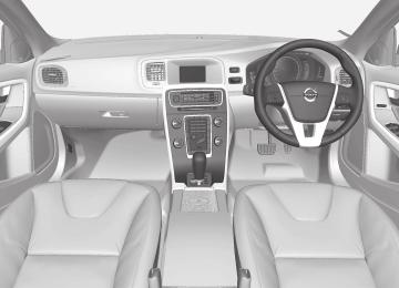
Instruments and controls, right-hand drive car - overview The overview shows where the car's displays and controls are located.
03
56
Overview, right-hand drive cars
03 Instruments and controls
03
}} 57
03 Instruments and controls ||
Function
See
03
Screen for infotain- ment system and display of menus
Ignition switch
START/STOP ENGINE button
Manual gear chang- ing in an automatic gearbox*
Cruise control*
Combined instru- ment panel
Horn, airbags
Menu navigation, audio control, phone control*
(p. 103) and the Sensus Infotainment supplement.
(p. 70).
(p. 264).
(p. 273).
(p. 185) and (p. 188).
(p. 59).
(p. 76) and (p. 28).
(p. 103) and the Sensus Infotainment supplement.
Function
Control panel
Headlamp control, opener for fuel filler flap and tailgate
See
(p. 165), (p. 170), (p. 92) and (p. 94).
(p. 78), (p. 300) and (p. 167).
Function
See
Control panel for infotainment system and menu naviga- tion
(p. 103) and the Sensus Infotainment supplement.
Hazard warning flashers
(p. 86).
Seat adjustment*
(p. 73).
Bonnet opener
(p. 343).
Related information • Outside temperature gauge (p. 67) • Trip meter (p. 68) • Clock (p. 68)
Parking brake
Steering wheel adjustment
Menus and mes- sages, direction indicators, main/ dipped beam, trip computer
Gear selector
Controls for active chassis (Four-C)*
(p. 293).
(p. 76).
(p. 100), (p. 102), (p. 87), (p. 81) and (p. 112).
(p. 271), (p. 273) or (p. 276).
(p. 175).
Wipers and washing
(p. 90).
Door handle
–
Control panel for cli- mate control
(p. 121).
58
* Option/accessory, for more information, see Introduction.
Combined instrument panel The combined instrument panel's information display shows information on some of the car's functions, as well as messages. • Analogue combined instrument panel -
overview (p. 59)
• Digital combined instrument panel - over-
view (p. 60)
• Combined instrument panel - meaning of
indicator symbols (p. 64)
• Combined instrument cluster - meaning
of warning symbols (p. 65)
03 Instruments and controls
Gauges and indicators
Analogue combined instrument panel - overview The combined instrument panel's information display shows information on some of the car's functions, e.g. cruise control and trip computer, as well as messages. The informa- tion is shown with symbols and text.
Information display
Fuel gauge. When the indicator lowers to only one white marking1, the yellow indi- cator symbol for low level in the fuel tank is illuminated. See also Trip computer - supplementary information (p. 112) and Filling up with fuel (p. 300). Eco meter The meter provides an indica- tion of how economically the car is being driven. The higher the reading on the scale, the more economical it is. Speedometer
Information display, analogue instrument panel. The combined instrument panel's information display shows information on some of the car's functions, e.g. cruise control and trip computer, as well as messages. The informa- tion is shown with symbols and text. There are further descriptions under the functions that use the display.
1 When the display's message "Distance to empty fuel tank:" starts to show "----", the marking becomes red.
03
59
03 Instruments and controls ||
Tachometer. The meter indicates engine speed in thousands of revolutions per minute (rpm). Gear shift indicator2/Gear position indica- tor3 See also Gear shift indicator* (p. 272), Automatic gearbox -- Geartronic* (p. 273) or Automatic gearbox -- Powershift* (p. 276).
03
Indicator and warning symbols
Indicator and warning symbols, analogue instru- ment panel.
Indicator symbols
Indicator and warning symbols
warning symbols4
Functionality check All indicator and warning symbols, apart from symbols in the centre of the information dis- play, illuminate in key position II or when the engine is started. When the engine has started, all the symbols should go out except the parking brake symbol, which only goes out when the brake is disengaged. If the engine does not start or if the function- ality check is carried out in key position II then all symbols go out within a few seconds except the symbol for faults in the car's emis- sions system and the symbol for low oil pres- sure.
Related information • Combined instrument panel (p. 59) • Combined instrument panel - meaning of
indicator symbols (p. 64)
• Combined instrument cluster - meaning
of warning symbols (p. 65)
Digital combined instrument panel - overview The combined instrument panel's information display shows information on some of the car's functions, e.g. cruise control and trip computer, as well as messages. The informa- tion is shown with symbols and text.
Information display
Information display, digital instrument panel*. The combined instrument panel's information display shows information on some of the car's functions, e.g. cruise control and trip computer, as well as messages. The informa- tion is shown with symbols and text. There are further descriptions under the functions that use the display.
2 Manual gearbox 3 Automatic gearbox 4 For certain engine variants, the symbol for low oil pressure is not used. Warnings are made via display text; see Engine oil - checking and filling (p. 346).
60
* Option/accessory, for more information, see Introduction.
Gauges and indicators, digital instrument panel Alternative themes can be selected for the digital combined instrument panel. Possible themes are "Elegance", "Eco" and "Performance". The setting for the theme can be stored in the remote control key's memory when locking the car; see pages Remote con- trol key with key blade (p. 149) and MY CAR (p. 103). A theme can only be selected when the engine is running. To select the theme, press the left-hand stalk switch's OK button and then select the Themes menu option by turning the thumb- wheel on the lever. Confirm your choice by pressing the OK button. For more information on menus, see Menu navigation - combined instrument panel (p. 100). The appearance of the centre console's screen follows the combined instrument pan- el's theme setting on certain model variants.
03 Instruments and controls
(p. 273) or Automatic gearbox -- Powershift* (p. 276).
Gauges and indicators, theme "Elegance".
Fuel gauge. When the indicator lowers to only one white marking5, the yellow indi- cator symbol for low level in the fuel tank is illuminated. See also Trip computer - supplementary information (p. 112) and Filling up with fuel (p. 300). Temperature gauge for engine coolant
Speedometer
Tachometer. The meter indicates engine speed in thousands of revolutions per minute (rpm). Gear shift indicator6/Gear position indica- tor7 See also Gear shift indicator* (p. 272), Automatic gearbox -- Geartronic*
Gauges and indicators, theme "Eco".
Fuel gauge. When the indicator lowers to only one white marking5, the yellow indi- cator symbol for low level in the fuel tank is illuminated. See also Trip computer - supplementary information (p. 112) and Filling up with fuel (p. 300). Eco guide. See also Eco guide & Power guide* (p. 63). Speedometer
Tachometer. The meter indicates engine speed in thousands of revolutions per minute (rpm). Gear shift indicator6/Gear position indica- tor7. See also Gear shift indicator* (p.
5 When the display's message "Distance to empty fuel tank:" starts to show "----", the marking becomes red. 6 Manual gearbox 7 Automatic gearbox
* Option/accessory, for more information, see Introduction.
03
}} 61
03 Instruments and controls ||
272), Automatic gearbox -- Geartronic* (p. 273) or Automatic gearbox -- Powershift* (p. 276).
Power guide. See also Eco guide & Power guide* (p. 63). Gear shift indicator6/Gear position indica- tor7. See also Gear shift indicator* (p. 272), Automatic gearbox -- Geartronic* (p. 273) or Automatic gearbox -- Powershift* (p. 276).
Indicator and warning symbols
03
Gauges and indicators, theme "Performance".
Fuel gauge. When the indicator lowers to only one white marking5, the yellow indi- cator symbol for low level in the fuel tank is illuminated. See also Trip computer - supplementary information (p. 112) and Filling up with fuel (p. 300). Temperature gauge for engine coolant
Speedometer
Tachometer. The meter indicates engine speed in thousands of revolutions per minute (rpm).
Indicator and warning symbols, digital instrument panel.
Indicator symbols
Indicator and warning symbols
warning symbols8
Functionality check All indicator and warning symbols, apart from symbols in the centre of the information dis- play, illuminate in key position II or when the engine is started. When the engine has started, all the symbols should go out except the parking brake symbol, which only goes out when the brake is disengaged. If the engine does not start or if the function- ality check is carried out in key position II then all symbols go out within a few seconds except the symbol for faults in the car's emis- sions system and the symbol for low oil pres- sure.
Related information • Combined instrument panel (p. 59) • Combined instrument panel - meaning of
indicator symbols (p. 64)
• Combined instrument cluster - meaning
of warning symbols (p. 65)
5 When the display's message "Distance to empty fuel tank:" starts to show "----", the marking becomes red. 6 Manual gearbox 7 Automatic gearbox 8 For certain engine variants, the symbol for low oil pressure is not used. Warnings are made via display text; see Engine oil - checking and filling (p. 346).
62
* Option/accessory, for more information, see Introduction.
Eco guide & Power guide* Eco guide and Power guide are two com- bined instrument panel (p. 59) instruments which help the driver to drive the car with optimum driving economy. The car also stores statistics of journeys made, which can be viewed in the form of a block diagram; see Trip computer - trip statis- tics* (p. 113).
Eco guide This instrument provides an indication of how economically the car is being driven. To view this function, select the theme "Eco"; see Digital combined instrument panel - over- view (p. 60).
Instantaneous value
Average value
9 Power is dependent on engine speed.
03 Instruments and controls
Instantaneous value The instantaneous value is shown here - the higher the reading on the scale, the better. The instantaneous value is calculated based on speed, engine speed, engine power uti- lised plus use of the foot brake. Optimum speed (50-80 km/h) and low engine speeds are encouraged. The pointers fall dur- ing acceleration and braking. Very low instantaneous values illuminate the red zone on the meter (with a short delay), which means poor driving economy and hence should be avoided. Average value The average value slowly follows the instanta- neous value and describes how the car has been driven most recently. The higher the pointers on the scale, the better the economy achieved by the driver.
Power guide This instrument shows the relationship between how much power (Power) is being taken from the engine and how much power is available. To view this function, select the theme "Performance"; see Digital combined instru- ment panel - overview (p. 60).
03
Available engine power
Engine power utilised
Available engine power The smaller, upper pointer shows the availa- ble engine power9. The higher the reading on the scale, the more power is available in the current gear. Engine power utilised The larger, lower pointer shows the engine power utilised9. The higher the reading on the scale, the more power is being taken from the engine. A large gap between the two pointers indi- cates a large power reserve.
* Option/accessory, for more information, see Introduction.
63
03 Instruments and controls
03
Combined instrument panel - meaning of indicator symbols The indicator symbols alert the driver that a function is activated, that the system is oper- ating, or that an error or failure has occurred.
Indicator symbols Symbol Specification
ABL fault
Emissions system
ABS fault
Rear fog lamp on
Stability system
Stability system, sport mode
Engine preheater (diesel)
Low level in fuel tank
Information, read display text
Main beam On
Left-hand direction indicator
Symbol Specification
Right-hand direction indicator
Eco-function on, see ECO* (p. 288)
Start/Stop, the engine auto- stopped; see Start/Stop* - function and operation (p. 280)
Tyre pressure system*, see Tyre pressure monitoring* (p. 330)
ABL fault The symbol illuminates if a fault has arisen in the ABL function (Active Bending Lights).
Emissions system If the symbol illuminates after the engine has been started then it may be due to a fault in the car's emissions system. Drive to a work- shop for checking. Volvo recommends that you seek assistance from an authorised Volvo workshop.
ABS fault If this symbol illuminates then the system is not working. The car's regular brake system continues to work, but without the ABS func- tion. 1. Stop the car in a safe place and turn off
the engine.
2. Restart the engine. 3.
If the symbol remains illuminated, drive to a workshop to have the ABS system checked. Volvo recommends that you seek assistance from an authorised Volvo workshop.
Rear fog lamp on This symbol illuminates when the rear fog lamp is switched on.
Stability system A flashing symbol indicates that the stability system is operating. If the symbol illuminates with constant glow then there is a fault in the system.
Stability system, sport mode Sport mode allows for a more active driving experience. The system then detects whether the accelerator pedal, steering wheel move- ments and cornering are more active than in normal driving and then allows controlled skidding of the rear section up to a certain level before it intervenes and stabilises the car.
Engine preheater (diesel) This symbol illuminates during engine pre- heating. Preheating mostly takes place due to low temperature.
Low level in fuel tank When the symbol illuminates the level in the fuel tank is low, refuel as soon as possible.
64
* Option/accessory, for more information, see Introduction.
03 Instruments and controls
Information, read display text When one of the car's systems does not behave as intended, this information symbol illuminates and a text appears on the informa- tion display. The message text is cleared with the OK button, see Menu navigation - com- bined instrument panel (p. 100), or it disap- pears automatically after a time (time depending on which function is indicated). The information symbol can also illuminate in conjunction with other symbols.
Tyre pressure system The symbol illuminates in the event of low tyre pressure, or if a fault arises in the tyre pressure system.
Related information • Combined instrument panel (p. 59) • Combined instrument cluster - meaning
of warning symbols (p. 65)
• Digital combined instrument panel - over-
view (p. 60)
Combined instrument cluster - meaning of warning symbols The warning symbols alert the driver that an important function is activated, or that a seri- ous error or a serious failure has occurred.
Warning symbols Symbol Specification
Low oil pressureA
03
NOTE
When a service message is shown, the symbol and message are cleared using the OK button, or disappear automatically after a time.
Main beam On The symbol illuminates when main beam is on and with main beam flash.
Left/right-hand direction indicator Both direction indicator symbols flash when the hazard warning flashers are used.
Eco function on The symbol illuminates when the Eco function is activated.
Start/Stop The symbol shines when the engine is auto- stopped.
Parking brake applied, digital instrument
Parking brake applied, ana- logue instrument
Airbags – SRS
Seatbelt reminder
Alternator not charging
Fault in brake system
Warning
A For certain engine variants, the symbol for low oil pressure
is not used. Warnings are made via display text; see Engine oil - checking and filling (p. 346).
Low oil pressure If this symbol illuminates during driving then the engine's oil pressure is too low. Stop the
65
03 Instruments and controls || engine immediately and check the engine oil level, top up if necessary. If the symbol illumi- nates and the oil level is normal, contact a workshop. Volvo recommends that you seek assistance from an authorised Volvo work- shop.
Alternator not charging This symbol illuminates during driving if a fault has occurred in the electrical system. Visit a workshop. Volvo recommends that you seek assistance from an authorised Volvo workshop.
Parking brake applied This symbol illuminates with a constant glow when the parking brake is applied. The sym- bol flashes during application, and then changes over to a constant glow. A flashing symbol in any other situation means that a fault has arisen. Read the mes- sage on the information display. For more information, see Parking brake (p. 293).
Airbags – SRS If this symbol remains illuminated or illumi- nates while driving, it means a fault has been detected in the seatbelt buckle, SRS, SIPS, or IC systems. Drive immediately to a workshop to have the system checked. Volvo recom- mends that you seek assistance from an authorised Volvo workshop.
Seatbelt reminder This symbol flashes if someone in a front seat has not put on their seatbelt or if someone in a rear seat has taken off their seatbelt.
Fault in brake system If this symbol illuminates, the brake fluid level may be too low. Stop the car in a safe place and check the level in the brake fluid reser- voir; see Brake and clutch fluid - level (p. 350). If the brake and ABS symbols illuminate at the same time, there may be a fault in the brake force distribution system. 1. Stop the car in a safe place and turn off
the engine.
2. Restart the engine.
• If both symbols extinguish, continue
driving.
• If the symbols remain illuminated,
check the level in the brake fluid reser- voir, see Brake and clutch fluid - level (p. 350). If the brake fluid level is nor- mal but the symbols are still illumi- nated, the car can be driven, with great care, to a workshop to have the brake system checked. Volvo recommends that you seek assistance from an authorised Volvo workshop.
WARNING
If the brake fluid is under the MIN level in the brake fluid reservoir, do not drive fur- ther before topping up the brake fluid. The loss of brake fluid must be investiga- ted by a workshop. Volvo recommends that you contact an authorised Volvo workshop.
WARNING
If the BRAKE and ABS symbols are lit at the same time, there is a risk that the rear end will skid during heavy braking.
Warning The red warning symbol illuminates when a fault has been indicated which could affect the safety and/or driveability of the car. An explanatory text is shown on the information display at the same time. The symbol remains visible until the fault has been rectified but the text message can be cleared with the OK button; see Menu navigation - combined instrument panel (p. 100). The warning sym- bol can also illuminate in conjunction with other symbols. Action: 1. Stop in a safe place. Do not drive the car
further.
03
66
2. Read the information on the information display. Implement the action in accord- ance with the message in the display. Clear the message using the OK button.
Reminder – doors not closed If one of the doors is not closed properly then the information or warning symbol illuminates together with an explanatory image in the information display. Stop the car in a safe place as soon as possible and close the door that is open.
If the car is driven at a speed lower than approx. 7 km/h then the informa-
tion symbol illuminates.
If the car is driven at a speed higher than approx. 7 km/h then the warning
symbol illuminates. If the bonnet10 is not closed properly then the warning symbol illuminates together with an explanatory image in the information display. Stop the car in a safe place as soon as possi- ble and close the bonnet. If the tailgate is not closed properly then the information symbol illuminates together with an explanatory image in the information dis- play. Stop the car in a safe place as soon as possible and close the tailgate.
10 Only cars with alarm*.
03 Instruments and controls
Related information • Combined instrument panel (p. 59) • Combined instrument panel - meaning of
indicator symbols (p. 64)
• Digital combined instrument panel - over-
view (p. 60)
Outside temperature gauge The display for the outside temperature gauge appears in the combined instrument panel.
03
Display for outside temperature gauge, digital instrument panel Display for outside temperature gauge, analogue instrument panel
When the temperature lies between +2 °C to -5 °C a snowflake symbol illuminates in the display. This warns of icy roads. If the car has been stationary then the gauge may show a reading that is too high.
Related information • Combined instrument panel (p. 59)
* Option/accessory, for more information, see Introduction.
67
03 Instruments and controls
Trip meter The trip meter display appears in the com- bined instrument panel.
Clock The clock display appears in the combined instrument panel.
Volvo Sensus Volvo Sensus is the heart of your personal Volvo experience. It is Sensus that provides information, entertainment and functions to simplify your ownership.
03
Trip meter, digital instrument. Display for trip meter11
Clock, digital instrument panel.
Display for showing the time12
Set the clock The clock can be adjusted in the menu sys- tem MY CAR, see MY CAR (p. 103).
Related information • Combined instrument panel (p. 59)
The two trip meters T1 and T2 are used for measuring short distances. The distance is shown in the display. Turn the left stalk switch thumbwheel to show the required meter. A long press (until the change occurs) on the left-hand stalk switch's RESET button resets the trip meter shown. For more information, see Trip computer - supplementary informa- tion (p. 112).
Related information • Combined instrument panel (p. 59)
When you are sitting in your car you want control, and in today's interconnected world, this includes information, communication and entertainment when it is most suitable for you. Sensus covers all our solutions that ena- ble connection* to the outside world, at the same time providing you with intuitive control over all the car's capabilities. Volvo Sensus combines and presents many functions in several of the car's systems on the centre console's display screen. With Volvo Sensus the car can be personalised by means of an intuitive user interface. Settings can be made in Car settings, Audio and media, Climate control, etc.
11 Display appearance may differ depending on instrument variant.
68
* Option/accessory, for more information, see Introduction.
With the centre console buttons and controls or the steering wheel's right-hand keypad* functions can be activated or deactivated and many different settings can be made. With a press on MY CAR all settings related to the driving and control of the car are pre- sented, such as City Safety, locks and alarm, automatic fan speed, setting the clock, etc. With a press on the respective function *, NAV* and CAM* RADIO, MEDIA, TEL*, other sources, systems and functions can be activated, e.g. AM, FM, CD, DVD*, TV*, Blue- tooth*, navigation* and park assist camera*. For more information about all functions/ systems, see the relevant section in the owner's manual or its supplement.
03 Instruments and controls
Overview
Related information • Licenses (p. 422)
03
Centre console control panel. The figure is sche- matic - the number of functions and layout of the buttons both vary, depending on the equipment selected and the market.
Navigation* - NAV, see separate supple- ment. Audio and media - RADIO, MEDIA, TEL*, see separate supplement (Sensus Info- tainment). Car settings - MY CAR, see MY CAR (p. 103). Internet-connected car - *, see sepa- rate supplement (Sensus Infotainment). Climate control system (p. 115).
Park assist camera (p. 244) – CAM*.
12 The time is shown in the centre of an analogue instrument panel.
* Option/accessory, for more information, see Introduction.
69
03 Instruments and controls
Key positions The remote control key can be used to set the vehicle's electrical system in different modes/ levels so that different functions are available; see Key positions - functions at different lev- els (p. 70).
03
the remote control key in the ignition switch.
2. Then press the remote control key in the
lock up to its end position.
IMPORTANT
Foreign objects in the ignition switch can impair the function or destroy the lock. Do not press in the remote control key incorrectly turned - hold the end with the detachable key blade, see Detachable key blade - detaching/attaching (p. 155).
Remove the remote control key Push the remote control key, allow it to eject, then pull it out from the ignition switch.
Key positions - functions at different levels In order to enable the use of a limited number of functions with the engine switched off, the car's electrical system can be set in 3 differ- ent levels (key positions) - 0, I and II - with the remote control key. Throughout this owner's manual these levels are described using the denomination "key positions".
The following table shows the functions avail- able in each key position/level.
Ignition switch with remote control key extrac- ted/inserted.
NOTE
For cars with the Keyless* function the remote control key does not need to be inserted into the ignition switch but can be stored in e.g. a pocket. For more informa- tion on Keyless functions, see Keyless drive* (p. 159).
Insert the remote control key 1. Hold the end of the remote control key
with the detachable key blade and insert
70
* Option/accessory, for more information, see Introduction.
03 Instruments and controls
Towing For important information about the remote control key during towing, see Towing (p. 313).
Related information • Key positions (p. 70)
03
Level Functions
II
• Odometer, clock and tem- perature gauge are illumi- nated.
• Power seats can be adjusted. • The audio system can be
used for a limited time - see the Sensus Infotainment sup- plement.
• Sunroof, power windows, 12V socket in the passenger com- partment, navigation, phone, ventilation fan and wind- screen wipers can be used.
• The headlamps come on. • Warning/indicator lamps illu-
minate for 5 seconds.
• Several other systems are
activated. However, heating in seat cushions and the rear window can only be activated after the engine has been started.
This key position consumes a lot of current from the battery and should therefore be avoi- ded!
13 Not necessary for cars with the Keyless* function. 14 Approx. 2 seconds.
Choosing key position/level • Key position 0 - Unlock the car - This
means that the car's electrical system is at level 0.
• Key position I - With the remote control key fully inserted into the ignition switch13
- Briefly press START/STOP ENGINE.NOTE
To reach level I or II without starting the engine - do not depress the brake/clutch pedal when these key positions are due to be selected.
• Key position II - With the remote control key fully inserted into the ignition switch13
- Give a long14 press on START/STOP ENGINE.• Back to key position 0 - To return to key
position 0 from position II and I - Briefly press on START/STOP ENGINE.
Audio system For information on audio system functions with remote control key removed, see the Sensus Infotainment supplement.
Starting and stopping the engine For information about starting/stopping the engine, see Starting the engine (p. 264).
* Option/accessory, for more information, see Introduction.
71
4. Push the seat forward so that the head restraint "locks" in under the glovebox.
Raising takes place in reverse order.
WARNING
Grasp the backrest and make sure that it is properly locked after being folded up in order to avoid personal injury in the event of sudden braking or an accident.
Related information • Seats, front - electrically operated (p.
73)
• Seats, rear (p. 74)
03 Instruments and controls
Seats, front The car's front seats have different setting options for optimum seating comfort.
WARNING
Adjust the position of the driver's seat before setting off, never while driving. Make sure that the seat is in locked posi- tion in order to avoid personal injury in the event of sudden braking or an accident.
Lowering the front seat backrest*16
03
Lumbar support adjustment, turn the wheel15. Forward/backward: lift the handle to adjust the distance to the steering wheel and pedals. Check that the seat is locked after changing position. Raise/lower* front edge of seat cushion, pump up/down. Adjust backrest rake, turn the wheel.
Raise/lower the seat, pump up/down.
Control panel for power seat*.
The passenger seat backrest can be folded forward to make room for long loads.
Move the seat as far back/down as possi- ble. Adjust the backrest to an upright position.
Lift the catches on the rear of the back- rest and fold it forward.
15 Also applies to power seat. 16 The sport seat backrest cannot be folded.
72
* Option/accessory, for more information, see Introduction.
03 Instruments and controls
Seats, front - electrically operated The car's front seats have different setting options for optimum seating comfort. The power seat can be moved forward/backward and up/down. The front edge of the seat cushion can be raised/lowered. The backrest angle can be changed.
Power seat*
Preparations The seats can be adjusted for a certain time after unlocking the door with the remote con- trol key without the key in the ignition switch. Seat adjustment is normally made in key position I and can always be made when the engine is running.
Seat with memory function*
2. Hold the button depressed to store set-
tings while depressing one of the memory buttons.
Using a stored setting Hold one of the memory buttons depressed until the seat and the door mirrors stop. If you release the button then the movement of the seat will stop.
Heated seats For heated seats, see Heated front seats* (p. 122) and Heated rear seat* (p. 122).
03
Related information • Seats, front (p. 72) • Seats, rear (p. 74)
Front edge of seat cushion up/down
Seat forward/backward and up/down
Backrest rake
The power front seats have overload protec- tion which is tripped if a seat is blocked by an object. If this happens, go to key position I or 0 and wait a short time before adjusting the seat again. Only one movement (forward/back/up/down) can be made at a time.
The memory function stores settings for the seat and the door mirrors.
Store setting
Memory button
Memory button
Memory button
Button for storing settings
1. Adjust the seat and the door mirrors.
* Option/accessory, for more information, see Introduction.
73
03 Instruments and controls
Key memory* in remote control key17
All remote control keys can be used by differ- ent drivers to store the settings for the driver's seat and door mirrors18.03
Proceed as follows in order to store the set- tings and use the key memory: • Adjust the seat as you want it. • Lock the car by pressing the lock button on the remote control key that you nor- mally use. This stores the positions of the seat and door mirrors in the remote con- trol key's memory19.
• Unlock the car (by pressing the unlock button on the same remote control key) and open the driver's door. The driver's seat and door mirrors will automatically adopt the positions that are stored in the
remote control key's memory (if the seat has been moved since you locked the car).
The key memory can be activated/deacti- vated in the menu system MY CAR. For a description of the menu system, see MY CAR (p. 103).
Emergency stop If the seat accidentally begins to move, press one of the setting buttons for the seat or memory buttons in order to stop the seat. Restarting to reach the seat position stored in the key memory is performed by pressing the unlock button on the remote control key. The driver's door must then be open.
WARNING
Risk of crushing! Make sure that children do not play with the controls. Check that there are no objects in front of, behind or under the seat during adjustment. Ensure that none of the rear seat passengers is in danger of becoming trapped.
Related information • Remote control key - functions (p. 151)
17 For key memory for Keyless function, see Keyless drive* - key memory (p. 162). 18 Only if the car is equipped with power seat with memory and retractable power door mirrors. 19 This setting does not affect settings that have been stored in the power seat's memory function.
74
* Option/accessory, for more information, see Introduction.
Seats, rear The rear seat backrest and the outer seat head restraints can be folded. The centre seat head restraint can be adjusted to suit the height of the passenger.
Head restraint, centre seat, rear
Adjust the head restraint according to pas- senger height so that the whole of the back of the head is covered if possible. Slide it up as required. To lower the head restraint again, the button (located in the centre between the backrest and head restraint, see illustration) must be pressed in while the head restraint is pressed down carefully.
Manual lowering of the outer head restraints, rear seat
The triple-section backrest can be folded in different ways.
03 Instruments and controls
NOTE
The front seats may need to be pushed forwards, and/or the backrests adjusted upwards, in order that the rear backrests can be folded forward fully.
• The left-hand section can be folded sepa-
rately.
• The centre section can be folded sepa-
rately.
• The right-hand section can only be folded
together with the centre section.
• If the entire backrest is to be folded then
the different sections should be folded separately.
If the centre backrest is being lowered - release and adjust the head restraint for the centre backrest, see the earlier sec- tion "Head restraint, centre seat, rear". The outer head restraints are lowered automatically when the outer backrests are lowered. Pull up the backrest's lock- while folding the backrest ing handle forward at the same time. A red indicator shows that the on the lock catch backrest is no longer locked in place.
NOTE
When the backrests have been lowered the head restraints must be moved for- ward slightly so as not to make contact with the seat cushion.
Raising takes place in reverse order.
03
}} 75
Pull the locking handle closest to the head restraint to fold the head restraint forward. The head restraint is moved back manually until a "click" can be heard.
WARNING
The head restraints must be in locked position after being raised.
Lowering the rear seat backrest
IMPORTANT
There must be no objects on the rear seat when the backrest is to be folded down. The seat belts must not be connected either. Otherwise there is a risk of damag- ing the rear seat upholstery.
03 Instruments and controls ||
NOTE
When the backrest has been raised, the red indicator should no longer be showing. If it is still showing then the backrest is not locked in place.
WARNING
Do not lower the outer head restraints if there are any passengers using of the outer seats.
Steering wheel The steering wheel can be adjusted in differ- ent positions and has controls for horn and cruise control, as well as menu, audio and phone control.
WARNING
03
Check that the backrests and head restraints in the rear seat are locked prop- erly after being folded up.
Electrical lowering of the rear seat's outer head restraints*
Move the head restraint back manually until a click is heard.
Adjusting
WARNING
The head restraints must be in locked position after being raised.
Related information • Seats, front (p. 72) • Seats, front - electrically operated (p. 73)