- 2004 Volvo C70 Owners Manuals
- Volvo C70 Owners Manuals
- 2011 Volvo C70 Owners Manuals
- Volvo C70 Owners Manuals
- 1998 Volvo C70 Owners Manuals
- Volvo C70 Owners Manuals
- 2005 Volvo C70 Owners Manuals
- Volvo C70 Owners Manuals
- 2000 Volvo C70 Owners Manuals
- Volvo C70 Owners Manuals
- 2007 Volvo C70 Owners Manuals
- Volvo C70 Owners Manuals
- 2006 Volvo C70 Owners Manuals
- Volvo C70 Owners Manuals
- 2012 Volvo C70 Owners Manuals
- Volvo C70 Owners Manuals
- 2002 Volvo C70 Owners Manuals
- Volvo C70 Owners Manuals
- 2013 Volvo C70 Owners Manuals
- Volvo C70 Owners Manuals
- 2008 Volvo C70 Owners Manuals
- Volvo C70 Owners Manuals
- 2009 Volvo C70 Owners Manuals
- Volvo C70 Owners Manuals
- 1999 Volvo C70 Owners Manuals
- Volvo C70 Owners Manuals
- 2001 Volvo C70 Owners Manuals
- Volvo C70 Owners Manuals
- 2003 Volvo C70 Owners Manuals
- Volvo C70 Owners Manuals
- Download PDF Manual
-
"Oxygenated fuels"
Some fuel suppliers sell gasoline containing "oxygenates" which are usually alcohols or ethers. In some areas, state or local laws require that the service pump be marked indicating use of alcohols or ethers. However, there are areas in which the pumps are unmarked. If you are not sure whether there is alcohol or ethers in the gasoline you buy, check with the service station operator. To meet seasonal air quality standards, some areas require the use of "oxygenated" fuel.
Volvo allows the use of the following "oxygenated fuels; however, the octane ratings listed on this page must still be met.
Alcohol — Ethanol
Fuels containing up to 10% ethanol by volume may be used.
Ethanol may also be referred to as Ethyl alcohol, or "Gasohol".
Ethers — MTBE
Fuels containing up to 15% MTBE may be used. Refueling
The fuel tank holds approximately 17.9 US gal. (68 liters) with sufficient volume left over to accommodate possible expansion of the fuel in hot weather. Be aware that the "usable" tank capacity will be somewhat less than the specified maximum. When the fuel level is low, such factors as ambient temperature, the fuel's "Reid vapor pressure" characteristics, and terrain can affect the fuel pumps' ability to supply the engine with an adequate supply of fuel. Therefore, it is advisable to refuel as soon as possible when the needle nears the red zone, or when the fuel warning light comes on. Fuel tank cover
The fuel tank cover (on the right rear fender) is locked and must be popped open using the control on the driver's door.
Open fuel filler cap slowly during hot weather conditions.
CAUTION:
· Do not refuel with the engine running. Turn the ignition off or to position I. If the ignition is on, an incorrect reading could occur in the fuel gauge.
· After refueling, close the fuel filler cap by turning it clockwise until it clicks into place *.
· Allow for fuel expansion by not overfilling the tank. Overfilling could also cause damage to the emission control systems.
· Avoid spilling gasoline during refueling. Gasolines containing alcohol can cause damage to painted surfaces, which may not be covered under the New Vehicle Limited Warranty.
· Do not use gasolines containing methanol (methyl alcohol, wood alcohol). This practice can result in vehicle performance deterioration and can damage critical parts in the fuel system. Such damage may not be covered under the New Vehicle Limited Warranty. * If the fuel filler cap is not closed tightly or if the engine is running when the car is refueled, the Malfunction Indicator Lamp may indicate a fault. However, your vehicle's performance will not be affected. Use only Volvo original or approved fuel filler caps.
pg. 58 Driving economy
Economical driving conserves natural resources
Better driving economy may be obtained by thinking ahead, avoiding rapid starts and stops and adjusting the speed of your vehicle to immediate traffic conditions. Observe the following rules:
· Bring the engine to normal operating temperature as soon as possible by driving with a light foot on the accelerator pedal for the first few minutes of operation. A cold engine uses more fuel and is subject to increased wear.
· Whenever possible, avoid using the car for driving short distances. This does not allow the engine to reach normal operating temperature.
· Drive carefully and avoid rapid acceleration and hard braking.
· Do not exceed speed limit.
· Avoid carrying unnecessary items (extra load) in the car.
· Maintain correct tire pressure. Check tire pressure regularly (check when tires are cold).
· Remove snow tires when threat of snow or ice has ended.
· Note that roof racks, ski racks, etc., increase air resistance and thereby fuel consumption.
· Avoid using automatic transmission kickdown feature unless necessary.
· Avoid using the air conditioning when it is not required. When engaged, the air conditioner's compressor places an additional load on the engine. However, please note that fuel consumption is lower with the air conditioning on than it is when driving with the air conditioning switched off and the windows down.
· If your car is equipped with the optional Trip Computer, utilizing the fuel consumption modes can help you "learn" how to drive more economically.
Other factors which decrease gas mileage are:
· Worn or dirty spark plugs
· Incorrect spark plug gap
· Dirty air cleaner
· Dirty engine oil and clogged oil filter
· Dragging brakes
· Incorrect front end alignment
Some of the above mentioned items and others are checked at the standard Maintenance Service intervals.
NOTE: (D)rive or 5th gear (manual transmissions) should be used as often as possible to help improve fuel economy.
pg. 59 Starting the engine
Starting and stopping
1. Fasten the seat belt.
WARNING! Before starting, check that the seat, steering wheel and mirrors are adjusted properly. Make sure the brake pedal can be depressed completely. Move the seat closer if necessary. Refer to section "front seats".
2. Apply the parking brake, if not already set. The gear selector (automatic transmission) is locked in the (P)ark position (SHIFT LOCK).
Manual transmission: the clutch must be fully depressed.
3. Without touching the accelerator pedal, turn the ignition key to the starting position*. Allow the starter to operate for up to 10 seconds. Release the key as soon as the engine starts. If the engine fails to start, repeat step 3.
For cold starts at altitudes above 6000 ft (1800 meters), depress the accelerator pedal halfway and turn the key to the starting position. Release the pedal slowly when the engine starts.
* If the key is left in the Drive position (position II) for more than 30 seconds, it must be turned to position 0 and then turned to the Start position (position III) again in order to start the car. See page 21 for ignition key positions.
4. To release the gear selector from the (P)ark position (automatic transmission), the ignition key must be in position II and the brake pedal must be depressed. See page 95 for instructions on manually releasing the SHIFTLOCK system.
Do not race a cold engine immediately after starting. Oil flow may not reach some lubrication points fast enough to prevent engine damage.
NOTE: (Automatic transmission only)
Your car is equipped with a KEYLOCK system. When the engine is switched off, the gear selector must be in the (P)ark position before the starting key can be removed from the ignition switch.
5. Select the desired gear. The gear engages after a slight delay (automatic transmission) which is especially noticeable when selecting R.
CAUTION: (Automatic transmission only)
The engine should be idling; never accelerate until after you feel the gear engage! Toorapid acceleration immediately after selecting a gear will cause harsh engagement and premature transmission wear.
NOTE: Selecting P or N (automatic transmission) when idling at a standstill for prolonged periods of time will help prevent overheating of transmission oil.
WARNING! Always place the gear selector (automatic transmission) in Park and apply the parking brake before leaving the vehicle. Never leave the car unattended with the engine running.
Always open the garage doors fully before starting the engine inside a garage to ensure adequate ventilation. The exhaust gases contain carbon monoxide, which is invisible and odorless but very poisonous.
CAUTION:
Never race the engine immediately after starting. Oil flow may not reach some lubricating points fast enough to prevent engine damage.
Do not race the engine just prior to switching off!
pg. 60 Manual transmission
Shift positions
Depress the clutch pedal completely when changing gears*.
Remove your foot from the clutch pedal while driving.
Overdrive (5th gear) should be used as often as possible to help improve fuel economy. This gear can be engaged at speeds above approx. 50 mph (80 km/h).
CAUTION: Follow the shift pattern indicated on the gear shift knob when shifting up (e.g., do not shift directly from 2nd to 5th gear) to help avoid excessive wear on the transmission.
Engaging reverse gear
The gear lever must first be moved to neutral in order to engage reverse gear.
CAUTION: Be careful that you do not inadvertently engage reverse while moving forward. * Clutch interlock (manual transmission only)
The clutch must be fully depressed before you can start your car. If the clutch is not depressed, it will not be possible to start the engine.
pg. 61 AW5 5-Speed Automatic Transmission
P (Park)
Use this position when starting the engine or parking the car.
Never use P while the car is in motion.
The parking brake should also be used when parking on grades.
The gear selector is mechanically locked in the P position (SHIFTLOCK). To release the gear selector from this position, the engine must be running (or the ignition key must be in position II) and the brake pedal must be depressed.
WARNING!
Never leave the car unattended when the engine is running. If, by mistake, the gear selector is moved from P, the car may start moving.
R (Reverse)
Never engage R while the car is moving forward. N (Neutral)
Neutral - no gear engaged. Use the parking brake.
D (Drive)
D is the normal driving position and should be used as often as possible to help improve fuel economy. The car should not be moving when shifting from R to the D position.
Neutral control
When the engine is idling, the gear selector is in the Drive position and the brake pedal is depressed, the
transmission will automatically switch to neutral.
The transmission will automatically return to Drive when the brake pedal is released.
This function has been added to help reduce emissions. 4 (Intermediate gear)
The transmission will shift automatically between gears 4, 3, 2 or 1 from this position.
The transmission cannot shift up to (D)rive from fourth gear. 3 (Intermediate gear)
The transmission will shift automatically between gears 3, 2 and 1 from this position.
The transmission cannot shift up to fourth gear or (D)rive from third gear. L (Low gears)
The transmission is locked in gears 1 and 2 when the selector is in this position.
NOTE:
· Gears 4, 3, or L can be used if you are driving in a mountainous area, towing a trailer or to increase engine braking effect.
· The transmission has a built-in limiter designed to help prevent excessive engine speeds (high rpm) when gears 4, 3
or L are selected. Automatic transmission - adaptive systemThe automatic transmission is controlled by an adaptive guidance system that constantly monitors the way in which the transmission functions. It senses and adapts each gear shift for optimal performance. The system also monitors your particular driving style and adapts gear shifting accordingly.
Contents | Top of Page
2 0 0 1 VOLVO
C70
Chapter 5 - Wheels and tires
pg. 73 Wheels and tires
The handling and riding comfort of the vehicle is dependent on the inflation pressure and the type of tires fitted. Read the following pages carefully.
General information, Wear indicator, Tire economy, Flat spots 74
Snow chains, Snow tires 75
Inflation pressure 76
Uniform tire quality grading 77pg. 74 Wheels and tires
General information
Your vehicle is equipped with tires according to the tire information label located on the rear facing side of the right front door.
The following is an example of a tire designation code 225/50R16:
225 = tire width in mm.
50 = tire profile. This is the relationship (in percent) between the section height and width of the tire.
R = radial tires.
16 = diameter in inches.
The tires have good road holding characteristics and offer good handling on dry and wet surfaces. It should be noted however that the tires have been developed to give these features on snow/icefree surfaces. Certain models are equipped with "all-season" tires, which provide a somewhat higher degree of road holding on slippery surfaces than tires without the "all-season" rating. However, for optimum road holding on icy or snow covered roads we recommend suitable winter tires on all four wheels. When replacing tires, be sure that the new tires are the same size designation, type (radial) and preferably from the same manufacturer, on all four wheels. Otherwise there is a risk of altering the car's roadholding and handling characteristics.
NOTE: When storing wheel/tire assemblies (e.g. winter tires and wheels), either stand the assemblies upright, or suspend them off the ground. Laying wheel/tire assemblies on their sides for prolonged periods can cause wheel and/or tire damage. Wear indicator
The tires have a socalled "wear indicator" in the form of a number of narrow strips running across or parallel to the tread. When approx. 1/16" (1.6 mm) is left on the tread, these strips become visible and indicate that the tire should be replaced.
Tires with less than 1/16" (1.6 mm) tread have a very poor grip in rain or snow.
When replacing worn tires, it is recommended that the tire be identical in type (radial) and size as the one being replaced. Using a tire of the same make (manufacturer) will prevent alteration of the driving characteristics of the vehicle. To improve tire economy:
· Maintain correct tire pressure.
· Drive smoothly: avoid fast starts, hard braking and tire screeching.
· Tire wear increases with speed.
· Correct front wheel alignment is very important.
· Unbalanced wheels impair tire economy and driving comfort.
· If the wheels are rotated, they should be kept on the same side of the car so that they revolve in the same direction as prior to rotation.
· Hitting curbs or potholes can damage the tires and/or wheels permanently. Flat spots
All tires become warm during use. After cooling, when the vehicle is parked, the tires have a tendency to distort slightly, forming flat spots. These flat spots can cause vibrations similar to the vibrations caused by unbalanced wheels. They do, however, disappear when the tire warms up. The degree to which flat spots form depends on the type of cord used in the tire. Remember that, in cold weather, it takes longer for the tire to warm up and consequently longer for the flat spot to disappear.
CAUTION: The car must not be driven with wheels of different dimensions. The use of different size wheels can seriously damage your car's transmission.
pg. 75 Wheels and tires
Snow chains
Snow chains can be used on your Volvo with the following restrictions:
· Snow chains should be installed on front wheels only. Use only Volvo approved snow chains.
· Snow chains may be mounted on tire dimension 195/65R15. Tire dimension 205/55R16 requires a special type of snow chain. Consult your Volvo retailer.
If accessory, aftermarket or "custom" tires and wheels are installed and are of a size different than the original tires and wheels, chains in some cases CANNOT be used. Snow chains cannot be used on those models fitted with all- season tires 225/50 R16 or 225/45 R17 or 225/40R18. Sufficient clearances between chains and brakes, suspension and body components must be maintained.
· Some strapon type chains will interfere with brake components and therefore CANNOT be used.
Consult your Volvo retailer for additional snow chain information.
CAUTION:
· Check local regulations regarding the use of snow chains before installing.
· Always follow the chain manufacturer's installation instructions carefully. Install chains as tightly as possible and retighten periodically.
· Never exceed the chain manufacturer's specified maximum speed limit. (Under no circumstances should that limit be higher than 30 mph (45 km/h).
· Avoid bumps, holes or sharp turns when driving with snow chains.
· The handling of the vehicle can be adversely affected when driving with chains. Avoid fast or sharp turns as well as locked wheel braking.
Snow tires, studded tires *
Tires for winter use:
Owners who live in or regularly commute through areas with sustained periods of snow or icy driving conditions are strongly advised to fit suitable winter tires to help retain the highest degree of traction.
It is important to install winter tires on all four wheels to help retain traction during cornering, braking, and accelerating. Failure to do so could reduce traction to an unsafe level or adversely affect handling. Do not mix tires of different design as this could also negatively affect overall tire road grip. Volvo recommends 195/65 R15 winter tires on 15" steel wheels on all C70 models including those equipped with 16", 17" or 18" wheels.
Winter tires wear more quickly on dry roads in warm weather. They should be removed when the winter driving season has ended.
Studded tires should be runin 300-600 miles (500-1000 km) during which the car should be driven as smoothly as possible to give the studs the opportunity to seat properly in the tires. The car tires should have the same rotational direction throughout their entire lifetime. In other words, if you wish to rotate the wheels, make sure that the same wheels are always on the same side of the car.
NOTE: Please consult state or provincial regulations restricting the use of studded winter tires before installing such tires. * Where permitted.
pg. 76 Wheels and tires
Checking and correcting tire pressure
· Check the tire pressure when refuelling.
· The tire pressure should be corrected only when the tires are cold.
· With warm tires, correct only when the pressure is too low. The tire temperature rises after driving just a few miles. Vehicle loading
The tires on your Volvo will perform to specifications at all normal loads when inflated as recommended on the tire information label* located on the rear facing edge of the passenger's door. This label lists both tire and vehicle design limits.
Do not load your car beyond the load limits indicated.
*Please note that the tire information label indicates pressure for both comfort and fuel economy.
pg. 77 Wheels and tires
Uniform tire quality grading
ALL PASSENGER CAR TIRES MUST CONFORM TO FEDER-AL SAFETY REQUIREMENTS IN ADDITION TO THESE GRADES
Quality grades can be found, where applicable, on the tire sidewall between the tread shoulder and maximum section width. For example: Treadwear 200 Traction AA Temperature A
TREADWEAR
The treadwear grade is a comparative rating based on the wear rate of the tire when tested under controlled conditions on a specified government test course. For example, a tire graded 150 would wear one and one half (1 1/2) times as well on the government course as a tire graded 100. The relative performance of tires depends upon the actual
conditions of their use, however, and many depart significantly from the norm due to variation in driving habits, service practices and differences in road characteristics and climate.
TRACTION
The traction grades, from highest to lowest, are AA, A, B, and C, as measured under controlled conditions on specified government test surfaces of asphalt and concrete. A tire marked C may have poor traction performance.
WARNING! The traction grade assigned to this tire is based on braking (straight-ahead) traction tests and does not include cornering (turning) traction.
TEMPERATURE
The temperature grades are AA (the highest), A, B, and C, representing the tire's resistance to the generation of heat and its ability to dissipate heat when tested under controlled conditions on a specified indoor laboratory test wheel. Sustained high temperature can cause the material of the tire to degenerate and reduce tire life, and excessive temperature can lead to sudden tire failure. The grade C corresponds to a minimum level of performance which all passenger car tires must meet under the Federal Motor Safety Standard No. 109. Grades B and A represent higher levels of performance on the laboratory test wheel than the minimum required by law.
WARNING! The temperature grade for this tire is established for a tire that is properly inflated and not overloaded. Excessive speed, underinflation, or excessive loading, either separately or in combination, can cause heat buildup and possible tire failure.
pg. 78 This page left intentionally blank
Contents | Top of Page
2 0 0 1 VOLVO
C70
Chapter 6 - In case of an emergency
pg. 79 In case of an emergency
Even if you maintain your car in good running condition, there is always the possibility that something might go wrong and prevent you from driving, such as a punctured tire, blown fuse or bulb, etc. For additional information, see section "ON CALL Road Assistance".
Wheel changing 80-81
Spare tire 82
Replacing bulbs 83-88
Replacing fuses 89-91Installation of accessories 92
Replacing wiper blades 93-94
In case of emergency 95
pg. 80 Wheel changing
Changing a wheel
The spare wheel is located under the carpet on the trunk floor. The jack and crank are secured in the wheel recess.
· Engage the parking brake.
· Put the gear selector in (P)ark (automatic) or in Reverse (manual).
· With the car still on the ground, use the lug wrench to loosen the wheel bolts 1/2 -1 turn. Turn the bolts counterclockwise to loosen.
· Fold out the crank handle on the jack by pressing the knob on the handle downward. To attach the jack, refer to the illustration on the following page.
CAUTION: The car must not be driven with wheels of different dimensions or with a spare tire other than the one that came with the car. The use of different size wheels can seriously damage your car's transmission.
NOTE: To avoid excessive wear and the necessity of rebalancing, mark and reinstall wheels in the same location and position as before removal. To lessen the chance of imbalance, each wheel hub is equipped with a guide stud to ensure that a removed wheel can be reinstalled in its original position (as when changing over to winter tires/wheels).
pg. 81 Wheel changing
There is a jack attachment located in the center on each side of the car. Position the jack on the bar in the attachment as shown in illustration above and crank while simultaneously guiding the base of the jack to the ground. The base of the jack must be flat on a level, firm, non-slippery surface. Before raising the car, check that the jack is still correctly positioned in the attachment. Raise the vehicle until both wheels on the side of the car where the jack is attached are lifted off the ground. Unscrew the wheel bolts completely and carefully remove the wheel so as not to damage the thread on the studs. Installing the wheel
Clean the contact surfaces on the wheel and hub. Lift the wheel and place it on the hub. Make sure that you align the wheel with the guide stud on the wheel hub prior to installation. Install the wheel bolts crosswise (see illustration) and tighten by turning lightly clockwise. Lower the vehicle to the ground and alternately tighten the bolts to 100 ft. lbs. (136 Nm). Install the wheel cap (where applicable).
WARNING!
· The jack's attachment must engage the bar in the jack attachment (A). The car's weight must not rest on the jack attachment (B).
· Be sure the jack is on a firm, level, non-slippery surface.
· Never allow any part of your body to be extended under a car supported by a jack.
· Use the jack intended for the car when replacing a wheel. For any other job, use stands to support the side of the car being worked on. -
· Apply the parking brake, select position P (automatic transmission) or Reverse gear (manual transmission).
· Block the wheels standing on the ground, use rigid wooden blocks or large stones.
· The jack should be kept well-greased.
CAUTION: Correct tightening torque on wheel bolts must be observed. The wheel bolts should never be greased or lubricated. The extended, chromed wheel bolts must not be used with steel rims, as they make it impossible to fit the hub caps.
Correct tightening order for wheel bolts
pg. 82 Spare tire
Temporary Spare (certain models)
The spare tire in your car is called a "Temporary Spare". It has the following designation: T125/90R15.
Recommended tire pressure (see decal on fuel filler flap) should be maintained irrespective of which position on the car the Temporary Spare tire is used on.
In the event of damage to this tire, a new one can be purchased from your Volvo retailer.
CAUTION: The car must not be driven with wheels of different dimensions or with a spare tire other than the one that
came with the car. The use of different size wheels can seriously damage your car's transmission.
WARNING!
Current legislation prohibits the use of the "Temporary Spare" tire other than as a temporary replacement for a punctured tire. In other words, it must be replaced as soon as possible by a standard tire. Roadholding, etc., may be affected with the "Temporary Spare" in use. Do not, therefore, exceed 50 mph (80 km/h).
pg. 83 Replacing bulbs
Parking light/direction indicator
1. From the front of the car, use a screwdriver to press down on the silver catch (located in the space between the inside of the fender and the headlight unit) to release the lamp housing from the front fender.
2. Turn the bulb holder 1/4 turn clockwise (viewed from the front) and withdraw it from the from the lamp housing. Leave the connector with its wires in the bulb holder.
4. Remove the bulb from the holder by pulling it straight out.
5. Press a new bulb into the holder and reinstall the unit in the reverse order.
Side direction indicator
1. Slide the lens forward and pull out the rear edge.
2. Pull out the entire lens/bulb unit.
3. With the lens toward you, turn the bulb holder 1/4 turn (the wires should not be disconnected from the holder) and pull out the bulb holder from the lens unit.
4. Pull the old bulb straight out and press a new one into place.
5. Replace the entire unit in the reverse order.
pg. 84 Replacing bulbs
Low beam headlight bulb (A) replacement
1. Turn the plastic cover counterclockwise and remove it.
2. Press the wire catches on the retaining clamp (1 in inset illustration above) together and push out (2) to release the bulb and connector from the headlight housing.
3. Pull the bulb out of the connector.
4. Insert a new bulb into the connector.
5. Reinsert the bulb and connector into the headlight housing. The guide lug must be up to ensure proper positioning.
6. Press the retaining clamp back into position.
7. Reinstall the plastic cover. The marking "Top" on the cover should be up when the cover is reinstalled.
CAUTION! Do not touch the glass on halogen bulbs with your fingers. Grease, oil, or any other impurities can be carbonized onto the bulb and cause damage to the reflector. Be sure to use bulbs of the correct tupe and voltage.
High beam headlight bulb (B) replacement
1. Pull the catch on the lower edge of the cover upward and remove the plastic cover.
2. Press the wire catches on the retaining clamp (1 in inset illustration above) together and push out (2) to release the bulb and connector from the headlight housing.
3. Pull the bulb out of the connector.
4. Insert a new bulb into the connector.
5. Reinsert the bulb and connector into the headlight housing. The guide lug must be up to ensure proper positioning.
6. Press the retaining clamp back into position.
7. Reinstall the plastic cover. Catch B should snap into position.
Contents | Top of Page
2 0 0 1 VOLVO
C70
Chapter 7 - Car care
pg. 97 Car care
Car care includes not only maintaining the appearance of the car, but also protecting the car exterior from the effects of air pollution, rain, mud or road salt. The paintwork should also be touched up immediately, if damaged, to prevent rust formation.
Paint touchup 98-99
Washing 100
Automatic car washing, Polishing and waxing 101
Cleaning the upholstery 102pg. 98 Paint touch up
Paint touchup
Paint damage requires immediate attention to avoid rusting. Make it a habit to check the finish regularly when washing the car for instance. Touchup if necessary.
Paint repairs require special equipment and skill. Contact your Volvo retailer for any extensive damage.
Minor scratches can be repaired by using Volvo touchup paint.
NOTE: When ordering touchup paint from your Volvo retailer, use the paint code indicated on the model plate. The plate is located in the engine compartment, on the inside of the left front fender.
h2>Minor stone chips and scratches
Material:
Primer can
Paint touchup bottle
Brush
Masking tape
NOTE: When touching up the car, it should be clean and dry. The surface temperature should be above 60° F (15° C). Scratches on the surface
If the stone chip has not penetrated down to the metal and an undamaged layer of paint remains, the touchup paint can be applied as soon as the spot has been cleaned.
pg. 99 Paint touch up
Deep scratches
1. Place a strip of masking tape over the damaged surface. Pull the tape off so that any loose flakes of paint adhere to it.
2. Thoroughly mix the primer and apply it with a small brush. When the primer surface is dry, the paint can be applied using a brush. Mix the paint thoroughly; apply several thin paint coats and let dry after each application.
3. If there is a longer scratch, you may want to protect surrounding paint by masking it off.
pg. 100 Washing
Washing the car
· The car should be washed at regular intervals since dirt, dust, insects and tar spots adhere to the paint and may cause damage.
NOTE: It is particularly important to wash the car frequently in the wintertime to prevent corrosion, when salt has been used on the roads.
· When washing the car, do not expose it to direct sunlight. Use lukewarm water to soften the dirt before you wash with a sponge, and plenty of water, to avoid scratching.
· Bird droppings: Remove from paintwork as soon as possible. Otherwise the finish may be permanently damaged.
· A detergent can be used to facilitate the softening of dirt and oil.
· A water-soluble grease solvent may be used in cases of sticky dirt. However, use a wash place equipped with a drainage separator.
· Dry the car with a clean chamois and remember to clean the drain holes in the doors and rocker panels *.
· The power radio antenna must be dried after washing.
· Tar spots can be removed with kerosene or tar remover after the car has been washed.
· A stiff-bristle brush and lukewarm soapy water can be used to clean the wiper blades. Frequent cleaning improves visibility considerably.
· Wash off the dirt from the underside (wheel housings, fenders, etc.).
· In areas of high industrial fallout, more frequent washing is recommended.
CAUTION: During high pressure washing, the spray mouthpiece must never be closer to the vehicle than 13" (30
cm). Do not spray into the locks.· When washing or steam cleaning the engine, avoid spraying water or steam directly on the electrical components or toward the rear side of the engine.
· After cleaning the engine, the spark plug wells should be inspected for water and blown dry if necessary.
Suitable detergents
Special car washing detergents should be used. A suitable mixture is about 2.5 fl. oz. (8.5 cl) of detergent to 2.6 US gal. (10 liters) of warm water. After washing with a detergent the car should be well rinsed with clean water.
WARNING!
· When the car is driven immediately after being washed, apply the brakes several times in order to remove any moisture from the brake linings.
· Engine cleaning agents should not be used when the engine is warm. This constitutes a fire risk.
NOTE: When washing the car, remember to remove dirt from the drain holes in the doors and sills. Bumpers: Wash the bumpers with the same cleaning agent used on the rest of the car. Never clean the bumpers with gasoline or paint thinner. Difficult spots can be removed with denatured alcohol. To avoid scratches, do not dry the bumpers with paper.
* Pay special attention to the drain holes near the base of the windshield in the cowl under the rear edge of the hood.
pg. 101 Automatic car washing, Polishing and waxing
Automatic washing simple and quick
An automatic wash is a simple and quick way to clean your car, but it is worth remembering that it may not be as thorough as when you yourself go over the car with sponge and water. Keeping the underbody clean is most important, especially in the winter. Some automatic washers do not have facilities for washing the underbody.
Before driving into an automatic wash, make sure that side view mirrors, auxiliary lamps, etc., are secure, otherwise there is risk of the machine dislodging them. You should also lower the antenna by turning off the radio.
We do NOT recommend washing your car in an automatic wash during the first six months (because the paint will not have hardened sufficiently). Polishing and waxing
Normally, polishing is not required during the first year after delivery, however, waxing may be beneficial.
Before applying polish or wax the car must be washed and dried. Tar spots can be removed with kerosene or tar remover. Difficult spots may require a fine rubbing compound.
After polishing use liquid or paste wax.
Several commercially available products contain both polish and wax.
Waxing alone does not substitute for polishing of a dull surface.
A wide range of polymerbased car waxes can be purchased today. These waxes are easy to use and produce a longlasting, highgloss finish that protects the bodywork against oxidation, road dirt and fading.
pg. 102 Cleaning the upholstery
Cleaning the upholstery
The fabric can be cleaned with soapy water or a detergent. For more difficult spots caused by oil, ice cream, shoe polish, grease, etc., use a clothing/fabric stain remover.
The plastic in the upholstery can be cleaned with a soft cloth and mild soap solution.
Leather upholstery can be cleaned with a soft cloth and mild soap solution. For more difficult spots, Volvo offers a leather care kit.
On no account must gasoline, naphtha or similar cleaning agents be used on the plastic or the leather since these can cause damage. Cleaning the seat belts
Clean only with lukewarm water and mild soap solution. Cleaning floor mats
The floor mats should be vacuumed or brushed clean regularly, especially during winter when they should be taken out for drying. Spots on textile mats can be removed with a mild detergent. Bear in mind
· Take extra care when removing stains such as ink or lipstick since the coloring can spread.
· Use solvents sparingly. Too much solvent can damage the seat padding.
· Start from the outside of the stain and work toward the center.
Contents | Top of Page
2 0 0 1 VOLVO
C70
Chapter 8 - Volvo Service
pg. 103 Volvo Service
Service an investment
An investment which will pay dividends in the form of improved reliability, durability and resale value.
Label information 104
Maintenance service, Warranty 105Maintenance schedule 106-107
Servicing 108-109Fuel/emissions systems 110
Lubrication 111Engine oil 112-113
Power steering fluid, Brake/clutch system fluid reservoir 114
Windshield washer nozzle, Washer fluid reservoir 115
Coolant 116
Engine compartment 117
Battery maintenance 118
PROPOSITION 65 WARNING 118pg. 104 Label information
1 Vehicle Emission Control Information
Your Volvo is designed to meet all applicable emission standards, as evidenced by the certification label on the underside of the hood. For further information regarding these regulations, please consult your Volvo retailer.
2 Vacuum hose routing
(underside of hood)
3 Loads and Tire Pressures (on rear edge of passenger's door)
4 Model plate
Vehicle Identification Number (VIN). Codes for color and upholstery, etc. This plate is located in the engine compartment, on the inside of the left front fender.
5 Vehicle Identification Number (VIN) *
The VIN plate is located on the top left surface of the dashboard. The VIN is also stamped on the right hand door pillar.
6 Federal Motor Vehicle Safety Standards (FMVSS) specifications (USA) and Ministry of Transport (CMVSS) standards (Canada)
Your Volvo is designed to meet all applicable safety standards, as evidenced by the certification label on the rear edge of the driver's door. For further information regarding these regulations, please consult your Volvo retailer.
* The Vehicle Identification Number (VIN) should always be quoted in all correspondence concerning your vehicle with the retailer and when ordering parts.
** These decals are located on the underside of the hood.
All specifications are subject to change without notice.
pg. 105 Maintenance service, Warranty
Maintenance service
Volvo advises you to follow the service program which is outlined in the Warranty and Service Records Information Booklet. This maintenance program contains inspections and services necessary for the proper function of your car. The maintenance services contain several checks which require special instruments and tools and therefore must be performed by a qualified technician. To keep your Volvo in top condition, specify time tested and proven Genuine Volvo Parts and Accessories. The Federal Clean Air Act U.S.
The Clean Air Act requires vehicle manufacturers to furnish written instructions to the ultimate purchaser to assure the proper functioning of those components that control emissions. The maintenance instructions listed in the "Servicing" section of this Manual represent the minimum maintenance required. These services are not covered by the warranty. You will be required to pay for labor and material used. Refer to your Warranty and Service Records Information Booklet for further details. Maintenance services
Your Volvo has passed several major inspections before being delivered to you, according to Volvo specifications. The maintenance services outlined in this book should be performed as indicated. The extended maintenance service intervals make it even more advisable to follow this program. Inspection and service should also be performed any time a malfunction is observed or suspected. It is recommended that receipts for vehicle emission services be retained in the event that questions arise concerning maintenance. Please refer to the Service Maintenance Record section of the Warranty and Service Records Information Booklet. Applicable warranties U.S. and Canada
In accordance with U.S. Federal Regulations, the following list of applicable U.S. warranties is provided. For Canadian specification vehicles, see your separate warranty booklet.
· New Car Limited Warranty - US
· New Car Limited Warranty - Canada
· Parts and Accessories Limited Warranty
· Corrosion Protection Limited Warranty
· Seat belt and Supplemental Restraint Systems Limited Warranty - US
· Seat belt and Supplemental Restraint Systems Limited Warranty - Canada
· Emission Performance Warranty - US and Province of British Columbia only
· Emission Design and Defect Warranty
These are the Federal warranties; other warranties are provided as required by laws in your state or province. Refer to your separate Warranty and Service Records Information Booklet for detailed information concerning each of the warranties.
pg. 106 Maintenance schedule
MAINTENANCE SCHEDULE
2001
C70
For complete maintenance information, please refer to your Warranty and Service Records Information Booklet.
A = Adjust (Correct if necessary) R = Replace I = Inspect (Correct or Replace if necessary) L = Lubricate
Maintenance Operation
82.5 90 2
thousand miles 7.5 15 22.5 30 37.5 45 52.5 60 67.5
(thousand km) (12) (24) (36) (48) (60) (72) (84) (96) (108) (120) (132) (144)75
EMISSION SYSTEM MAINTENANCE
Engine oil and filter 1
Engine drive belt (accessory belt) Air cleaner filter Spark plugs Automatic transmission fluid Timing belt - all engines3R R R R
R R
R R
1) See section "Engine oil" for detailed information.
NOTE: The oil should be changed at these intervals, after 750 hours of driving or after 12 months,
whichever occurs first.
2) For services beyond 90,000 miles (144,000 km), please refer to the Warranty and Service Records Information Booklet".
3) For proper functioning of the vehicle and its emission control systems, the timing belt and tensioner must be replaced every 105,000 miles (168,000 km).
pg. 107 Maintenance schedule
MAINTENANCE SCHEDULE
2001
C70
A = Adjust (Correct if necessary) R = Replace I = Inspect (Correct or Replace if necessary) L = Lubricate
Maintenance Operation
thousand miles 7.5 15 22.5 30 37.5 45 52.5 60 67.5
75
82.5
90
(thousand km) (12) (24) (36) (48) (60) (72) (84) (96) (108) (120) (132) (144)
EMISSION SYSTEM MAINTENANCE
Engine Fuel line filter1
PCV nipple (orifice)/hoses, clean Battery (check charge and electrolyte level) Brakes Inspect brake pads, replace components as necessary Brake fluid level2 - check Steering/suspension Tires3, check pressure, wear and condition Check power steering fluid level Body Power antenna (clean) Trunk/hood, hinges and latches Cabin air filter (see page 109)1) Replace at 105,000 miles (168,000 km)
2) Brake fluid should be changed at owner request every second year or 30,000 miles (48,000 km). The fluid should be replaced once a year or every 15,000 miles (24,000 km) when driving under extremely hard conditions (mountain driving, etc.).
3) Rotate tires at owner request.
The following items should be checked weekly by the driver (it takes only a few minutes):
Engine oil level, brake fluid level, radiator coolant level, operation of all lights, horns, windshield wipers, tire pressure (all five tires), windshield washer fluid level
The following should also be carried out at regular intervals:
Washing (check all drain holes), polishing, cleaning
pg. 108 Servicing
Hoisting the car
If a garage jack is used to lift the car, the two jack attachments points should be used. They are specially reinforced to bear the weight of the car. A garage jack can also be placed under the front of the engine support frame and under the reinforced plate in the spare wheel well. Take care not to damage the splash guard under the engine. Ensure that the jack is positioned so that the car cannot slide off it. Always use axle stands or similar structures.
If a twopost hoist is used to lift the car, the front lift arm pads should be positioned under the rear engine frame mounts. The rear lift arm pads should be positioned under the rear supporting arm bracket.
CAUTION: Certain models have reduced ground clearance due to the design of the front spoiler. Please observe caution when driving the car onto a garage hoist.
pg. 109 Servicing
Air cleaner
Replace the air cleaner cartridge with a new one every 30,000 miles (48,000 km). The cartridge should be replaced more often when driving under dirty and dusty conditions. The filter cannot be cleaned and therefore should always be replaced with a new one. Timing belt
For proper functioning of the vehicle and its emission control systems, the timing belt and tensioner must be replaced every 105,000 miles (168,000 km). Engine damage will occur if the belt fails. Fuel system cap, tank and lines and connections
The effectiveness of the fuel system to contain hydrocarbons is dependent largely on a leakfree system. Check for proper sealing of the fuel filler cap which contains "O" ring type seals.
NOTE: If the fuel filler cap is not closed tightly or if the engine is running when the car is refueled, the Malfunction Indicator Lamp ("Check Engine") may indicate a fault. However, your vehicle's performance will not be affected. Use only Volvo original or approved fuel filler caps. Fuel (line) filter
For proper functioning of the vehicle and its emission control systems, the fuel line filter should be replaced at 105,000
miles (168,000 km). The filter is replaced as one complete unit. Replace more frequently if contaminated fuel is introduced into the tank (or if there is reason to suspect that this has occurred). PCV systemThe orifice nipple in the intake manifold and the filter at the end of the PCV hose in the air cleaner should be
inspected at 60,000 miles (96,000 km) and thereafter, at 30,000 mile (48,000 km) intervals. Cabin air filter
Replace the cabin air filter with a new one at 15,000 mile (24,000 km) intervals. Volvo recommends replacing the filter more often if the car is driven under dirty and dusty conditions. The filter cannot be cleaned and therefore should always be replaced with a new one.
pg. 110 Fuel/emissions systems
Fuel system
The fuel system is allelectronic and is microprocessorcontrolled. It can continually compensate for variation in engine load, speed and temperature to give the best economy and power. A mass air flow sensor measures the inducted air. In this way the system can make instantaneous adjustments for changes in air temperature or density, thus always assuring the best economy with the lowest possible exhaust emissions. Heated oxygen sensor
This is an emission control system designed to reduce emissions and improve fuel economy. The heated oxygen sensor monitors the composition of the exhaust gases leaving the engine. The exhaust gas analysis is fed into an electronic module. This adjusts the airfuel ratio to provide optimum conditions for combustion and efficient reduction of the three major pollutants (hydrocarbons, carbon monoxide and oxides of nitrogen (NOx) by a threeway catalytic converter.
Crankcase ventilation
The engine is provided with positive crankcase ventilation which prevents crankcase gases from being released into the atmosphere. Instead, the crankcase gases are admitted to the intake manifold and cylinders. Evaporative control system
The car is equipped with an evaporative control system which prevents gasoline vapor from being released into the atmosphere.
The system consists of a fuel tank with filler pipe and cap, a rollover valve, a Fill Limit Vent Valve (FLVV), vapor vent lines, a charcoal canister, a purge line, a purge control valve and engine connections .
In addition, there is a pressure sensor connected to the fuel tank and a filter-protected Canister Close Valve (CCV) on the atmospheric side of the canister, for system diagnosis.
The gasoline vapor is channeled through the rollover valve and the FLVV via the vapor vent lines into the charcoal
canister, where it is stored. When the engine is started, the gasoline vapor is drawn from the charcoal canister to the engine's air intake system and into the combustion process.
NOTE:
· If the fuel filler cap is not closed tightly or if the engine is running when the car is refueled, the Malfunction Indicator Lamp may indicate a fault.
· During a transitional period, a small number of service stations may still have fuel nozzles that are not compatible with the fuel filler neck on cars equipped with the evaporative control system (ORVR) mandated by the U.S. Environmental Protection Agency and the California Air Resources Board. If you experience difficulties in refueling your vehicle, please ask the gas station attendant for assistance.
CAUTION:
Fuel must not be siphoned from the fuel tank. This will damage the Evaporative control system.
pg. 111 Lubrication
Sun roof wind deflector (visible when sun roof is open) Oil, low temperature grease
No. Lubrication point 1 Hood lock and latch 2 Door stop and hinges 4 Door lock catch plate
Power antenna Locks Trunk lock catch plate Front seat side rail and latch
lubricant Oil Oil
Oil WD 40 or similar Volvo teflon lock spray Low temperature grease Oil
To avoid rattles and unnecessary wear, the body should be lubricated at regular service intervals. This should be done by an authorized Volvo retailer.
Contents | Top of Page
2 0 0 1 VOLVO
C70
Chapter 9 - Specifications
pg. 119 Specifications
Specifications
This chapter contains facts and figures pertaining to the technical specifications of your car.
Oil/fluids specifications 120
Engine specifications 121
Cooling/fuel/distributor ignition systems 122
Front/rear suspensions 122
Transmission, Capacities, Vehicle loading 123
Electrical system/bulbs 124
Dimensions and weights 125
Service manuals, Road assistance 126pg. 120 Oil/fluid specifications
Oil quality
Engine Oil
Meeting or exceeding ILSAC specification GF-2, including ACEA A1, API SJ, SJ/CF, and SJ/Energy Conserving.
Oil additives must not be used unless advised by an authorized Volvo retailer. Engine oil Automatic transmission fluid Manual
Quality: Meeting or exceeding ILSAC specification GF-2, including ACEA A1, API SJ, SJ/CF, and SJ/Energy Conserving. Quality: AW5: Only Volvo gearbox oil (1161540-8). Do not mix with other oils.
Capacity (incl. filter): 6.1
US qts. (5.8 liters)* Capacity: 8 US qts. (7.6
liters)transmission fluid Power steering fluid Brake fluid
Quality: Volvo synthetic gearbox oil 1161423
Quality: ATF
Quality: DOT 4+
All specifications are subject to change without notice.
pg. 121 Engine specifications
Capacity: 2.2 US qts. (2.1
liters) Capacity: 0.95 US qts. (0.9 liters) Capacity: 0.64 US qts. (0.6 liters)Engine
Liquid-cooled gasoline, 5cylinder, inline engine. Aluminum alloy cylinder block with castiron cylinder liners cast directly into the block. Aluminum alloy cylinder head with double overhead camshafts and separate intake and outlet channels.
Engine lubrication is provided by an eccentric pump driven from the crankshaft. Fullflow type oil filter. Exhaust emission control is accomplished by multiport fuel injection, heated oxygen sensor(s) and threeway catalytic converter. Designation: Output Max. torque Number of cylinders Bore Stroke Displacement Compression ratio Number of valves
Volvo B 5244 T 190 hp at 5100 rpm (142 kW/85 rps) 199 ft. lbs. at 1600-5000 rpm (270
Nm/27-83 rps) 3.27" (83 mm) 3.54" (90 mm) 2.4 liters 9.0:1Volvo B 5234 T3
236 hp at 5400 rpm (176 kW/90 rps) 243 ft. lbs. at 24005100 rpm (330
Nm/4592 rps) 3.19" (81 mm) 3.54" (90 mm) 2.3 liters 8.5:1Designation: Output Max. torque Number of cylinders Bore Stroke Displacement Compression ratio Number of valves
20
20
All specifications are subject to change without notice.
pg. 122 Specifications
Cooling system
Type: Positive pressure, closed system
Thermostat begins to open at 180° F (87° C)
Coolant: Volvo original coolant/antifreeze
Capacity: 7.4 US qts. (7.0 liters) Fuel system
The engine is equipped with a multiport fuel injection system. Distributor ignition system
12453
Firing order: Distributor ignition setting: Not adjustable Spark plugs: Spark plug gap: Tightening torque:
Champion RC8PYP (or equivalent) 0.03" (0.75 mm) 18.4 ft. lbs. +/ 3.7 ft. lbs. (25 Nm +/ 5 Nm)
WARNING! The distributor ignition system operates at very high voltages. Special safety precautions must be followed to prevent injury. Always turn the ignition off when:
· Replacing distributor ignition components e.g. plugs, coil, etc.
· Do not touch any part of the distributor ignition system while the engine is running. This may result in unintended movements and body injury.
Replacing spark plugs
The spark plugs should be changed every 30,000 miles (48,000 km). However, city driving or fast highway driving may necessitate changing after 15,000 miles (24,000 km) of driving. When installing new plugs, be sure to fit the right type and use correct torque, see "Specifications". When changing the plugs, check that the suppressor connectors are in good condition. Cracked or damaged connectors should be replaced. When changing the spark plugs, clean the terminals and the rubber seals. Front suspension
Spring strut suspension with integrated shock absorbers and control arms linked to the support frame. Powerassisted rack and pinion steering. Safety type steering column.
The alignment specifications apply to an unladen car but include fuel, coolant and spare wheel.
Toe-in measured on the wheel rims: 2.4 mm +/ 0.7 mm
Toe-in measured on tire sides: 2.9 +/ 0.9 mm Rear suspension
Deltalink individual rear wheel suspension with longitudinal support arms, double link arms and track rods.
Toe-in measured on the tire sides: 4° +/ 10°
All specifications are subject to change without notice.
pg. 123 Specifications
Power transmission
Manual transmission: M 56 H
Singledisc dry plate clutch. Allsynchromesh on all gears including reverse; integrated final drive. Operation via a floor mounted gear lever.
Final drive ratio 4.00:1
Reduction ratios 1st gear 2nd gear 3rd gear 4th gear 5th gear Reverse3.07:1
1.77:1
1.19:1
0.87:1
0.70:1
2.99:1Automatic transmission: AW 50-50 LE
5-speed automatic electronically controlled gearbox comprising a hydraulic torque converter with a lockup function; planetary gear, integrated final drive.
Operation via a floor mounted gear selector lever. Drive shafts with symmetrical joint location. Overdrive. Final drive ratio 2.76:1 (Turbocharged models: 2.56:1) Reduction ratios AW5
4.77:1
1st gear 2.10:1
2nd gear 3rd gear 1.96:1
1.32:1
4th gear 1.02:1
5th gear Reverse 3.23:1Capacities
17.9 US gal. (68 liters) 7.4 US qts. (7.0 liters)
Fuel tank Cooling system Engine oil (incl. filter) 6.1 US qts. ( 5.8 liters) * Automatic transmission 2 US gals (7.6 liters) Manual transmission 2.2 US qts. (2.1 liters) Power steering fluid 0.8 US qts (0.8 liters) Washer fluid reservoir 4.7 US qts. (4.5 liters)
Brake/clutch system
0.6 US qts (0.6 liters)
Vehicle loading
The tires on your Volvo should perform to specifications at all normal loads when inflated as recommended on the tire information label. The label is located on the inside of the fuel filler flap. The label lists both tire and vehicle design limits. Do not load your car beyond the load limits indicated.
WARNING! Improperly inflated tires will reduce tire life, adversely affect vehicle handling and can possibly lead to failure resulting in loss of vehicle control without prior warning.
All specifications are subject to change without notice.
pg. 124 Specifications
Electrical system
12 Volt, negative ground.
Voltagecontrolled generator. Singlewire system with chassis and engine used as conductors.
Battery
Voltage 12 Volt
Capacity 520 A/100 min
(certain markets) 420 A/75 min
The battery contains corrosive and poisonous acids. It is of the utmost importance that old batteries are disposed of correctly. Your Volvo retailer can assist you in this matter.
Generator
Rated output 1400 W
Max. current 100 A Bulbs
Bulb Headlights High beam Low beam Front parking lights/turn signals Turn signals, rear
US no. Power
Socket
No/bulbs
55W 55W
H7
H7
3357NA 30/7W/30/2.2cp W 2.5 x 15q 2BAU 15
21W
Side direction indicators Tail lights 67
Brake lights 1156
Backup lights 1156
Rear fog light 1156
Front fog lights H1
License plate light Door open warning light Door step courtesy lights Trunk light Glove compartment light Vanity mirror lights Instrument lighting Illumination, control panel gear selector (auto matic trans.) rear ashtray Instrument warning/indicator lights - Front courtesy lights Rear reading lights5W 5W/4cp 21W/32cp 21W/32cp 21W/32cp 55 W 5 W 3 W 5W 10 W 2 W 1.2 W 3 W 1.2 W 1.2 W 1.2 W 1.2 W 5 W 5 W
W 2.1x9.5 d 2
BA 15 s BA 15 s BA 15 s BA 15 s P14.5s W 2.1x9.5d 2
W 2.1x9.5d 4
W 2.1x9.5d 2
SV 8.5
BA 9s W 2.1x9.5d 3
W 2x4.6 d W 2x4.6d W 2x4.6d W 2x4.6d BA 9s BA 9sAll specifications are subject to change without notice.
pg. 125 Specifications
Dimensions and weights - Volvo C 70
Length Width Height Wheelbase Track, front Track, rear Turning circle (between curbs) 39 ft. (11.9 m) Cargo capacity
185.8 in. (472 cm) 71.7 in. (182 cm) 55.1 in. (140 cm) 104.7 in. (266 cm) 59.8 in. (151.8 cm) 59.7 in. (151.6 cm)
13.1 cu. ft. (0.37m3)
WARNING! When adding accessories, equipment, luggage and other cargo to your vehicle, the total loaded weight capacity of the vehicle must not be exceeded.
USA
Canada
4190 lbs (1900 kg) 4140 lbs (1878 kg) 785 lbs (356 kg) 3305-3405 lbs (1499-1544 kg) 1500-1545 kg
1900 kg 1880 kg 355 kg
Gross vehicle weight (GVW) (aut.) (man.) Capacity weight * Curb weight Permissible axle weight, front 2360 lbs (1070 kg) (aut.) 2310 lbs (1048 kg) (man.) Permissible axle weight, rear 1940 lbs (880 kg) Max roof load 220 lbs (100 kg) Max trailer weight (w/o brakes) 1100 lbs (500 kg) Max trailer weight (with brakes) 2" ball 1 7/8" ball Max tongue weight **
3300 lbs (1500 kg) 1500 kg 2000 lbs (908 kg) 165 lbs (75 kg)
1070 kg 1050 kg 880 kg 100 kg 500 kg
900 kg 75 kg
* The max permissible axle loads or the gross vehicle weight must not be exceeded.
** See also section "Trailer towing" All specifications are subject to change without notice.
pg. 126 Road Assistance
Volvo supports Voluntary Mechanic Certification by the A.S.E. Certified mechanics have demonstrated a high degree of competence in specific areas. Besides passing exams each mechanic must also have worked in the field for two or more years before a certificate is issued. These professional mechanics are fully able to analyze vehicle problems and perform the necessary service procedures to keep your Volvo at peak operating condition.
NOTE: The above pertains to the USA only.
Your new Volvo comes with a four year road assistance program named ONCALL. Additional information, features, and benefits are described in a separate information package in your glove compartment.
If you have misplaced your package, dial:
In the U.S.A.
1-800-63-VOLVO (1-800-638-6586)
In Canada:
1-800-263-0475 All specifications are subject to change without notice.
Contents | Top of Page
2 0 0 1 VOLVO
C70
Chapter 10 - Audio systems
pg. 127 Audio systems
Audio systems
This chapter describes the audio system in your car.
SC-813 128
SC-816 141
SC-901 157
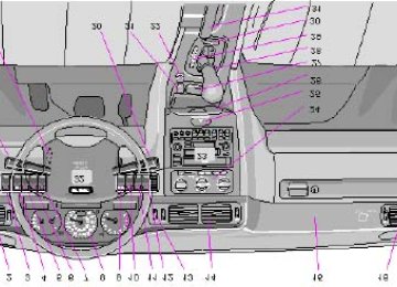
General information 180pg. 128 Audio system SC813 (certain models)
The following pages describe the use of your SC813 Cassette radio and CD remote control
1. On/off (push)
2. · Volume (turn)
· Pause/Mute (push)
· Balance (pull)
3. Active Sound Control
4. CD changer selector
5. · Tape mode selector
· Tape direction selector PROG
6. Bass control
7. Treble control
8. Fader control
9. · Preset buttons
· CD-Disc No. selector
10. PROG - Reversing the tape
11. Dolby B NR button
12. Cassette eject
13. Not in use
14. Scan
15. Auto seek memory
16. · Seek tuning up/down
· TP-Next/Previous song
· CD-Next UP/Previous DOWN track
17. · Manual tuning
· TP-fast forward/Rewind
· CD-Music searchUP/DOWN
18. RND button
19. Cassette slot
20. Display
21. Waveband selector (AM)
22. Waveband selectors (FM)
23. Anti-theft LED
TP = Applicable only in Tape Mode
CD = Applicable only when in CD mode and connected to a CD changer.
pg. 129 Anti-theft code
Anti-theft code
The radio features anti-theft circuitry. If the set is removed from the vehicle or if the battery power is disconnected, a special code must be entered to enable operation of the set.
Refer to the radio code card supplied with your vehicle or ask your retailer for the correct code.
When the car is parked with the ignition key removed, the anti-theft LED will flash.
To enter the code
After installation or when the set has been disconnected from power, the set displays "COdE" when it is switched on.
Enter the 4-digit code using the preset buttons.
If the correct code is entered, "on" is displayed and the set is ready to use.
If you enter an incorrect code you must enter the correct code again from the beginning.
Incorrect code
If an incorrect code has been entered "rPt" is displayed. Enter the correct code.
After three unsuccessful coding attempts the set will lock and remain locked for two hours. "OFF" is displayed.
During this waiting period:
· the battery must be connected
· the ignition key must be turned to position I
· the unit must be turned on
Make sure the headlights are turned off to help prevent battery drain (please refer to page 24 for information on turning the headlights off).
Enter the code again once this time has elapsed.
pg. 130 Radio SC-813
A - On/off switch
Push the button to switch on the radio. Press the button slightly longer to turn the radio off. B - Volume control
Turn the button clockwise to increase the volume. The volume control is electronic and has no end stop. C - Waveband selector
The desired waveband is set by pressing one of the waveband selector buttons. The frequency and waveband is shown on the display.
NOTE: There are two FM wavebands and one AM waveband. This makes it possible to store 2 x 6 FM stations and 6
AM stations in memory.D - Setting frequency selection
The radio can be used in most parts of the world by changing the frequency selection intervals as follows:
Depress and hold preset button 5 and turn the radio ON. "USA" will flash on the display.
Each time button 5 is pressed, the frequency selection will change from "USA" to "AUS", etc. When the correct country name is displayed, wait 5 seconds and the radio will be ready for use. E - Manual tuning
Press the left side tune button to tune to lower frequencies and the right side to tune to higher frequencies. The tuned frequency is displayed.
ST will be displayed to indicate stereo FM reception.
pg. 131 Radio SC-813
A - Seek tuning up/down
Press the left side tune button to tune to lower frequencies and the right side to tune to higher frequencies. The radio seeks the next audible station and stops there. If you wish to continue the seek tuning, press the tune button again. B - Preset programming
1. Tune to the desired frequency.
2. Depress and hold a preset button. The audio will cut out. Keep the button depressed until the audio comes on again (approx. 2 seconds).
3. The frequency is now stored on this preset button. C - Preset buttons
To select a pre-programed radio frequency, depress the preset button. The set frequency will be displayed.
pg. 132 Radio SC-813
A - Automatic programming (Auto)
Please note that this function will not interfere with pre-stored stations on buttons 1-6.
This function automatically seeks and stores up to 8 strong AM or FM stations.
This is especially useful when travelling in areas where radio stations are unfamiliar.
1. Depress and hold the "AUTO" button for at least 1 second. A number of strong stations (max. 8) on the chosen waveband are now automatically stored in the memory.
If there are no audible stations, "- - - -" is displayed.
2. Press the "AUTO" button (for less than 1 second) to obtain another autostored station. A new station will be selected each time the button is pressed momentarily. B - Bass control
Adjust the bass by sliding the control up or down (up to increase, down to decrease).
A "detent" indicates "equalized" bass. C - Treble control
Adjust the treble by sliding the control up or down (up to increase, down to decrease).
A "detent" indicates "equalized" treble.
pg. 133 Radio SC-813
A - Fader control
Adjust front/rear speaker balance by sliding the control up or down.
(Up to direct more sound to the front speakers, down to direct more sound to the rear speakers.
The "detent" indicates "equalized" front /rear balance position. B - Pause function
Press the "volume" knob to temporarily mute the sound. "PAUSE" is displayed. C - Balance control
Pull out the "volume" knob and adjust the left/right balance by turning the knob counter- clockwise or clockwise. D - Scan
Press this button to listen to each station for five seconds. Press it again to stop scanning. "Scan" will be displayed during scanning. E - Active sound control (ASC)
The ASC function automatically adjusts the volume level of the audio system according to driving speed. To deactivate ASC depress the "ASC" button.
To activate ASC, depress the "ASC" button until "ASC" is displayed.
Contents | Top of Page
2 0 0 1 VOLVO
C70
HomeLink® Universal Transceiver (option)
pg. 184 HomeLink® Universal Transceiver (option)
HomeLink® Universal Transceiver
HomeLink® is an advanced system that can be programmed to learn the codes of three different remote controlled- devices (e.g., garage door openers, remote lighting, entry door lock). HomeLink®'s sun visor-mounted transceiver, powered by your car's electrical system, may then be used in place of your hand-held remote controls.
NOTE: For your security, the HomeLink® Universal Transceiver is designed to not function if you lock your car from the outside.
Programming the transceiver
1. The ignition switch must be turned to the "accessory" position (II) before programming the HomeLink® Universal Transceiver.
Release the buttons.
2. Begin by erasing all 3 factory default channels. Hold down the two outside buttons (buttons 1 and 3 in the illustration) on the HomeLink® Universal Transceiver for about 20 seconds, until HomeLink® 's indicator light begins to flash. Then release the buttons.
3. Hold your hand-held transmitter (garage door opener, for example) 2 to 5 in. (5 to 12 cm) away from the HomeLink® surface, keeping the indicator light in view. For placement questions, contact HomeLink® toll-free 1- 800-355-3515 (Internet: www.HomeLink® .jci.com).
4. Using two hands, push and hold both your hand-held transmitter's button and the transceiver button you wish to
program. The indicator light will flash first slowly, then rapidly. Rapid flashing tells you the HomeLink® button has been successfully programmed. Release both buttons.
5. If you are programming a rolling code-equipped device (e.g., garage door opener or entry door lock), refer to "Programming rolling codes" on the next page to complete the programming process.
Repeat steps 3 and 4 to program the other two transceiver buttons. If, after several attempts, you are unable to successfully train the HomeLink® Universal Transceiver to learn your hand-held transmitter's signal, contact HomeLink® toll-free 1-800-355-3515 (Internet: www.HomeLink® .jci.com).
WARNING!
· If you use HomeLink® to open a garage door or gate, be sure no one is near the gate or door while it is in motion.
· Do not use the HomeLink® Universal Transceiver with any garage door opener that lacks safety "stop" and "reverse" features as required by federal safety standards. (This includes any garage door opener model manufactured before April 1, 1982) A garage door opener that cannot "detect" an object, signalling the door to "stop" and "reverse" does not meet current federal safety standards. Using a garage door opener without these features increases the risk of serious injury or death. For more information on this matter, call toll-free 1-800-355- 3515 (Internet: www.HomeLink® .jci.com).
pg. 185 HomeLink® Universal Transceiver (option)
NOTE - Canadian residents:
During programming, your hand-held transmitter may automatically stop transmitting. To successfully train HomeLink® , continue to hold the HomeLink® button. At the same time, repeatedly press and hold your hand-held transmitter's button at two-second intervals until HomeLink® has learned your transmitter's code. The HomeLink® indicator light will flash first slowly, and then rapidly to indicate that the button has been successfully programmed.
Determining if your garage door uses a rolling code
Determining if your garage door uses a rolling code Determine, in one of the following ways, if your garage door uses a rolling code system and is manufactured after 1996:
Refer to the garage door opener owner's manual for verification. If your hand-held transmitter appears to program the HomeLink® Universal Transceiver but the programmed button
does not activate the garage door, your garage door opener may have a rolling code.
Press the programmed HomeLink® button. If the garage door opener has the rolling code feature, the HomeLink®
indicator light flashes rapidly and then glows steadily after approximately 2 seconds.
To train a rolling code garage door opener , follow these instructions after programming the desired transceiver button according to "Programming the transceiver." The help of a second person may make training easier.
1. Locate the training button on the garage door opener motor head unit. The location and color of the training button may vary. If you encounter difficulty, refer to the garage door opener owner's manual or call toll-free 1-800-355-3515
(Internet: www.HomeLink® .jci.com).2. Press the "training" button on the garage door opener motor head unit until the "training" light comes on.
3. Press and release the programmed HomeLink® button. Press and release the programmed HomeLink® button a second time to complete the training process. Some garage door openers may require you to do this procedure a third time to complete the training.
The programmed button on your HomeLink® Universal Transceiver should now operate your garage door opener. The original hand-held transmitter can also be used, as desired, to operate the garage door.
Operating the HomeLink® Universal Transceiver Once programmed, the HomeLink® Universal Transceiver can be used in place of your hand-held transmitters.
To operate, the key must be turned to the "accessory" position (II) or the engine must be running. Press the programmed HomeLink® button to activate the garage door, driveway gate, security lighting, home security system, etc.
Your original hand-held transmitters may, of course, be used at any time.
Erasing programmed buttons
Individual buttons cannot be erased. To erase all three programmed buttons:
1. 1. Turn the ignition key to the "accessory" position (II).
2. Hold down the two outside buttons on the HomeLink® Universal Transceiver for about 20 seconds, until HomeLink® 's indicator light begins to flash.
3. Release both buttons.
The HomeLink® buttons can be reprogrammed using the procedures described on the previous page.
(HomeLink® information is continued on the next page)
pg. 186 HomeLink® Universal Transceiver (option)
Reprogramming a single HomeLink® button
1. Press and hold the desired HomeLink® button. Do not release the button until step 3 has been completed.
2. When the indicator light begins to flash slowly (after approximately 20 seconds), position the hand-held transmitter 2 to 5 in. (5 to 12 cm) away from the HomeLink® surface.
3. Press and hold the hand-held transmitter button. The HomeLink® indicator light will begin to flash, first slowly then rapidly. When the indicator light flashes rapidly, release both buttons.
The previously programmed device has now been erased and the new device can be activated by pressing the HomeLink® button that has just been programmed. This procedure will not affect any other programmed HomeLink® buttons.
NOTE:
· Retain the original transmitter(s) for future programming procedures (i.e., if you purchase a new car).
· It is also suggested that if you sell your car, the programmed channels on the HomeLink® Universal Transceiver be erased for security purposes.
Contents | Top of Page
2 0 0 1 VOLVO
C70
17
35
33
33
44
25
17,19,69
31180
128
141
157
48
101
24
61,62,63,64, 123
62
120118,124
54
118
12
17,18
114,120
18
69
17INDEX
pg. 194 - 196 Index
ABS Air conditioning Air mix Air vents Airbag (SIPS) Airbag (SRS) Alarm Ambient temperature sensor Anti-lock Brake System (ABS) Ashtrays Audio systems - General information - SC813
- SC816
- SC-900/901
Auto-dim (rear-view mirror) Automatic car washing Automatic daytime running Automatic transmission Kickdown Automatic transmission fluid Battery Battery drain - avoiding Battery maintenance Booster cushion Brake failure warning light Brake fluid Brake fluid warning light Brake system Brake warning light17,19
124123
36
75
80
12
10
12
16
25
114
60
116
19
17
64,122
20
49
29Bulb failure warning Bulbs Capacities Central locking button Chains (snow) Changing a wheel Child booster cushion Child Restraint Anchorages Child safety Clock Clock - resetting Clutch fluid Clutch interlock Coolant - checking/changing Coolant level sensor Coolant level warning light Cooling system Courtesy lights - exterior Courtesy lights - front Cruise control Daytime running lights Demister - rear window Dimensions Distributor ignition system Diversity antenna Doors and locks Driving economy Driving mode W EBD (Electronic Brake-force Distribution) 72
34,35
ECC - Electronic Climate Control 64,124
Electrical system 30
Electrically heated front seats 46,47
Electrically operated front seats 41
Electrically operated sun roof 36
Electrically-operated windows Electronic Brake Distribution (EBD) 70
Electronic Brake-force Distribution (EBD) 70