- 2004 Volvo C70 Owners Manuals
- Volvo C70 Owners Manuals
- 2011 Volvo C70 Owners Manuals
- Volvo C70 Owners Manuals
- 1998 Volvo C70 Owners Manuals
- Volvo C70 Owners Manuals
- 2005 Volvo C70 Owners Manuals
- Volvo C70 Owners Manuals
- 2000 Volvo C70 Owners Manuals
- Volvo C70 Owners Manuals
- 2007 Volvo C70 Owners Manuals
- Volvo C70 Owners Manuals
- 2006 Volvo C70 Owners Manuals
- Volvo C70 Owners Manuals
- 2012 Volvo C70 Owners Manuals
- Volvo C70 Owners Manuals
- 2002 Volvo C70 Owners Manuals
- Volvo C70 Owners Manuals
- 2013 Volvo C70 Owners Manuals
- Volvo C70 Owners Manuals
- 2008 Volvo C70 Owners Manuals
- Volvo C70 Owners Manuals
- 2009 Volvo C70 Owners Manuals
- Volvo C70 Owners Manuals
- 1999 Volvo C70 Owners Manuals
- Volvo C70 Owners Manuals
- 2001 Volvo C70 Owners Manuals
- Volvo C70 Owners Manuals
- 2003 Volvo C70 Owners Manuals
- Volvo C70 Owners Manuals
- Download PDF Manual
-
Quality: Meeting or exceeding ILSAC specification GF-2, including ACEA A1, API SJ, SJ/CF, and SJ/Energy Conserving. Quality: AW5: Only Volvo gearbox oil (1161540-8). Do not mix with other oils.
Capacity (incl. filter): 6.1
US qts. (5.8 liters)* Capacity: 8 US qts. (7.6
liters)transmission fluid Power steering fluid Brake fluid
Quality: Volvo synthetic gearbox oil 1161423
Quality: ATF
Quality: DOT 4+
All specifications are subject to change without notice.
pg. 121 Engine specifications
Capacity: 2.2 US qts. (2.1
liters) Capacity: 0.95 US qts. (0.9 liters) Capacity: 0.64 US qts. (0.6 liters)Engine
Liquid-cooled gasoline, 5cylinder, inline engine. Aluminum alloy cylinder block with castiron cylinder liners cast directly into the block. Aluminum alloy cylinder head with double overhead camshafts and separate intake and outlet channels.
Engine lubrication is provided by an eccentric pump driven from the crankshaft. Fullflow type oil filter. Exhaust emission control is accomplished by multiport fuel injection, heated oxygen sensor(s) and threeway catalytic converter. Designation: Output Max. torque Number of cylinders Bore Stroke Displacement Compression ratio Number of valves
Volvo B 5244 T 190 hp at 5100 rpm (142 kW/85 rps) 199 ft. lbs. at 1600-5000 rpm (270
Nm/27-83 rps) 3.27" (83 mm) 3.54" (90 mm) 2.4 liters 9.0:1Volvo B 5234 T3
236 hp at 5400 rpm (176 kW/90 rps) 243 ft. lbs. at 24005100 rpm (330
Nm/4592 rps) 3.19" (81 mm) 3.54" (90 mm) 2.3 liters 8.5:1Designation: Output Max. torque Number of cylinders Bore Stroke Displacement Compression ratio Number of valves
20
20
All specifications are subject to change without notice.
pg. 122 Specifications
Cooling system
Type: Positive pressure, closed system
Thermostat begins to open at 180° F (87° C)
Coolant: Volvo original coolant/antifreeze
Capacity: 7.4 US qts. (7.0 liters) Fuel system
The engine is equipped with a multiport fuel injection system. Distributor ignition system
12453
Firing order: Distributor ignition setting: Not adjustable Spark plugs: Spark plug gap: Tightening torque:
Champion RC8PYP (or equivalent) 0.03" (0.75 mm) 18.4 ft. lbs. +/ 3.7 ft. lbs. (25 Nm +/ 5 Nm)
WARNING! The distributor ignition system operates at very high voltages. Special safety precautions must be followed to prevent injury. Always turn the ignition off when:
· Replacing distributor ignition components e.g. plugs, coil, etc.
· Do not touch any part of the distributor ignition system while the engine is running. This may result in unintended movements and body injury.
Replacing spark plugs
The spark plugs should be changed every 30,000 miles (48,000 km). However, city driving or fast highway driving may necessitate changing after 15,000 miles (24,000 km) of driving. When installing new plugs, be sure to fit the right type and use correct torque, see "Specifications". When changing the plugs, check that the suppressor connectors are in good condition. Cracked or damaged connectors should be replaced. When changing the spark plugs, clean the terminals and the rubber seals. Front suspension
Spring strut suspension with integrated shock absorbers and control arms linked to the support frame. Powerassisted rack and pinion steering. Safety type steering column.
The alignment specifications apply to an unladen car but include fuel, coolant and spare wheel.
Toe-in measured on the wheel rims: 2.4 mm +/ 0.7 mm
Toe-in measured on tire sides: 2.9 +/ 0.9 mm Rear suspension
Deltalink individual rear wheel suspension with longitudinal support arms, double link arms and track rods.
Toe-in measured on the tire sides: 4° +/ 10°
All specifications are subject to change without notice.
pg. 123 Specifications
Power transmission
Manual transmission: M 56 H
Singledisc dry plate clutch. Allsynchromesh on all gears including reverse; integrated final drive. Operation via a floor mounted gear lever.
Final drive ratio 4.00:1
Reduction ratios 1st gear 2nd gear 3rd gear 4th gear 5th gear Reverse3.07:1
1.77:1
1.19:1
0.87:1
0.70:1
2.99:1Automatic transmission: AW 50-50 LE
5-speed automatic electronically controlled gearbox comprising a hydraulic torque converter with a lockup function; planetary gear, integrated final drive.
Operation via a floor mounted gear selector lever. Drive shafts with symmetrical joint location. Overdrive. Final drive ratio 2.76:1 (Turbocharged models: 2.56:1) Reduction ratios AW5
4.77:1
1st gear 2.10:1
2nd gear 3rd gear 1.96:1
1.32:1
4th gear 1.02:1
5th gear Reverse 3.23:1Capacities
17.9 US gal. (68 liters) 7.4 US qts. (7.0 liters)
Fuel tank Cooling system Engine oil (incl. filter) 6.1 US qts. ( 5.8 liters) * Automatic transmission 2 US gals (7.6 liters) Manual transmission 2.2 US qts. (2.1 liters) Power steering fluid 0.8 US qts (0.8 liters) Washer fluid reservoir 4.7 US qts. (4.5 liters)
Brake/clutch system
0.6 US qts (0.6 liters)
Vehicle loading
The tires on your Volvo should perform to specifications at all normal loads when inflated as recommended on the tire information label. The label is located on the inside of the fuel filler flap. The label lists both tire and vehicle design limits. Do not load your car beyond the load limits indicated.
WARNING! Improperly inflated tires will reduce tire life, adversely affect vehicle handling and can possibly lead to failure resulting in loss of vehicle control without prior warning.
All specifications are subject to change without notice.
pg. 124 Specifications
Electrical system
12 Volt, negative ground.
Voltagecontrolled generator. Singlewire system with chassis and engine used as conductors.
Battery
Voltage 12 Volt
Capacity 520 A/100 min
(certain markets) 420 A/75 min
The battery contains corrosive and poisonous acids. It is of the utmost importance that old batteries are disposed of correctly. Your Volvo retailer can assist you in this matter.
Generator
Rated output 1400 W
Max. current 100 A Bulbs
Bulb Headlights High beam Low beam Front parking lights/turn signals Turn signals, rear
US no. Power
Socket
No/bulbs
55W 55W
H7
H7
3357NA 30/7W/30/2.2cp W 2.5 x 15q 2BAU 15
21W
Side direction indicators Tail lights 67
Brake lights 1156
Backup lights 1156
Rear fog light 1156
Front fog lights H1
License plate light Door open warning light Door step courtesy lights Trunk light Glove compartment light Vanity mirror lights Instrument lighting Illumination, control panel gear selector (auto matic trans.) rear ashtray Instrument warning/indicator lights - Front courtesy lights Rear reading lights5W 5W/4cp 21W/32cp 21W/32cp 21W/32cp 55 W 5 W 3 W 5W 10 W 2 W 1.2 W 3 W 1.2 W 1.2 W 1.2 W 1.2 W 5 W 5 W
W 2.1x9.5 d 2
BA 15 s BA 15 s BA 15 s BA 15 s P14.5s W 2.1x9.5d 2
W 2.1x9.5d 4
W 2.1x9.5d 2
SV 8.5
BA 9s W 2.1x9.5d 3
W 2x4.6 d W 2x4.6d W 2x4.6d W 2x4.6d BA 9s BA 9sAll specifications are subject to change without notice.
pg. 125 Specifications
Dimensions and weights - Volvo C 70
Length Width Height Wheelbase Track, front Track, rear Turning circle (between curbs) 39 ft. (11.9 m) Cargo capacity
185.8 in. (472 cm) 71.7 in. (182 cm) 55.1 in. (140 cm) 104.7 in. (266 cm) 59.8 in. (151.8 cm) 59.7 in. (151.6 cm)
13.1 cu. ft. (0.37m3)
WARNING! When adding accessories, equipment, luggage and other cargo to your vehicle, the total loaded weight capacity of the vehicle must not be exceeded.
USA
Canada
4190 lbs (1900 kg) 4140 lbs (1878 kg) 785 lbs (356 kg) 3305-3405 lbs (1499-1544 kg) 1500-1545 kg
1900 kg 1880 kg 355 kg
Gross vehicle weight (GVW) (aut.) (man.) Capacity weight * Curb weight Permissible axle weight, front 2360 lbs (1070 kg) (aut.) 2310 lbs (1048 kg) (man.) Permissible axle weight, rear 1940 lbs (880 kg) Max roof load 220 lbs (100 kg) Max trailer weight (w/o brakes) 1100 lbs (500 kg) Max trailer weight (with brakes) 2" ball 1 7/8" ball Max tongue weight **
3300 lbs (1500 kg) 1500 kg 2000 lbs (908 kg) 165 lbs (75 kg)
1070 kg 1050 kg 880 kg 100 kg 500 kg
900 kg 75 kg
* The max permissible axle loads or the gross vehicle weight must not be exceeded.
** See also section "Trailer towing" All specifications are subject to change without notice.
pg. 126 Road Assistance
Volvo supports Voluntary Mechanic Certification by the A.S.E. Certified mechanics have demonstrated a high degree of competence in specific areas. Besides passing exams each mechanic must also have worked in the field for two or more years before a certificate is issued. These professional mechanics are fully able to analyze vehicle problems and perform the necessary service procedures to keep your Volvo at peak operating condition.
NOTE: The above pertains to the USA only.
Your new Volvo comes with a four year road assistance program named ONCALL. Additional information, features, and benefits are described in a separate information package in your glove compartment.
If you have misplaced your package, dial:
In the U.S.A.
1-800-63-VOLVO (1-800-638-6586)
In Canada:
1-800-263-0475 All specifications are subject to change without notice.
Contents | Top of Page
2 0 0 1 VOLVO
C70
Chapter 10 - Audio systems
pg. 127 Audio systems
Audio systems
This chapter describes the audio system in your car.
SC-813 128
SC-816 141
SC-901 157
General information 180pg. 128 Audio system SC813 (certain models)
The following pages describe the use of your SC813 Cassette radio and CD remote control
1. On/off (push)
2. · Volume (turn)
· Pause/Mute (push)
· Balance (pull)
3. Active Sound Control
4. CD changer selector
5. · Tape mode selector
· Tape direction selector PROG
6. Bass control
7. Treble control
8. Fader control
9. · Preset buttons
· CD-Disc No. selector
10. PROG - Reversing the tape
11. Dolby B NR button
12. Cassette eject
13. Not in use
14. Scan
15. Auto seek memory
16. · Seek tuning up/down
· TP-Next/Previous song
· CD-Next UP/Previous DOWN track
17. · Manual tuning
· TP-fast forward/Rewind
· CD-Music searchUP/DOWN
18. RND button
19. Cassette slot
20. Display
21. Waveband selector (AM)
22. Waveband selectors (FM)
23. Anti-theft LED
TP = Applicable only in Tape Mode
CD = Applicable only when in CD mode and connected to a CD changer.
pg. 129 Anti-theft code
Anti-theft code
The radio features anti-theft circuitry. If the set is removed from the vehicle or if the battery power is disconnected, a special code must be entered to enable operation of the set.
Refer to the radio code card supplied with your vehicle or ask your retailer for the correct code.
When the car is parked with the ignition key removed, the anti-theft LED will flash.
To enter the code
After installation or when the set has been disconnected from power, the set displays "COdE" when it is switched on.
Enter the 4-digit code using the preset buttons.
If the correct code is entered, "on" is displayed and the set is ready to use.
If you enter an incorrect code you must enter the correct code again from the beginning.
Incorrect code
If an incorrect code has been entered "rPt" is displayed. Enter the correct code.
After three unsuccessful coding attempts the set will lock and remain locked for two hours. "OFF" is displayed.
During this waiting period:
· the battery must be connected
· the ignition key must be turned to position I
· the unit must be turned on
Make sure the headlights are turned off to help prevent battery drain (please refer to page 24 for information on turning the headlights off).
Enter the code again once this time has elapsed.
pg. 130 Radio SC-813
A - On/off switch
Push the button to switch on the radio. Press the button slightly longer to turn the radio off. B - Volume control
Turn the button clockwise to increase the volume. The volume control is electronic and has no end stop. C - Waveband selector
The desired waveband is set by pressing one of the waveband selector buttons. The frequency and waveband is shown on the display.
NOTE: There are two FM wavebands and one AM waveband. This makes it possible to store 2 x 6 FM stations and 6
AM stations in memory.D - Setting frequency selection
The radio can be used in most parts of the world by changing the frequency selection intervals as follows:
Depress and hold preset button 5 and turn the radio ON. "USA" will flash on the display.
Each time button 5 is pressed, the frequency selection will change from "USA" to "AUS", etc. When the correct country name is displayed, wait 5 seconds and the radio will be ready for use. E - Manual tuning
Press the left side tune button to tune to lower frequencies and the right side to tune to higher frequencies. The tuned frequency is displayed.
ST will be displayed to indicate stereo FM reception.
pg. 131 Radio SC-813
A - Seek tuning up/down
Press the left side tune button to tune to lower frequencies and the right side to tune to higher frequencies. The radio seeks the next audible station and stops there. If you wish to continue the seek tuning, press the tune button again. B - Preset programming
1. Tune to the desired frequency.
2. Depress and hold a preset button. The audio will cut out. Keep the button depressed until the audio comes on again (approx. 2 seconds).
3. The frequency is now stored on this preset button. C - Preset buttons
To select a pre-programed radio frequency, depress the preset button. The set frequency will be displayed.
pg. 132 Radio SC-813
A - Automatic programming (Auto)
Please note that this function will not interfere with pre-stored stations on buttons 1-6.
This function automatically seeks and stores up to 8 strong AM or FM stations.
This is especially useful when travelling in areas where radio stations are unfamiliar.
1. Depress and hold the "AUTO" button for at least 1 second. A number of strong stations (max. 8) on the chosen waveband are now automatically stored in the memory.
If there are no audible stations, "- - - -" is displayed.
2. Press the "AUTO" button (for less than 1 second) to obtain another autostored station. A new station will be selected each time the button is pressed momentarily. B - Bass control
Adjust the bass by sliding the control up or down (up to increase, down to decrease).
A "detent" indicates "equalized" bass. C - Treble control
Adjust the treble by sliding the control up or down (up to increase, down to decrease).
A "detent" indicates "equalized" treble.
pg. 133 Radio SC-813
A - Fader control
Adjust front/rear speaker balance by sliding the control up or down.
(Up to direct more sound to the front speakers, down to direct more sound to the rear speakers.
The "detent" indicates "equalized" front /rear balance position. B - Pause function
Press the "volume" knob to temporarily mute the sound. "PAUSE" is displayed. C - Balance control
Pull out the "volume" knob and adjust the left/right balance by turning the knob counter- clockwise or clockwise. D - Scan
Press this button to listen to each station for five seconds. Press it again to stop scanning. "Scan" will be displayed during scanning. E - Active sound control (ASC)
The ASC function automatically adjusts the volume level of the audio system according to driving speed. To deactivate ASC depress the "ASC" button.
To activate ASC, depress the "ASC" button until "ASC" is displayed.
Contents | Top of Page
2 0 0 1 VOLVO
C70
HomeLink® Universal Transceiver (option)
pg. 184 HomeLink® Universal Transceiver (option)
HomeLink® Universal Transceiver
HomeLink® is an advanced system that can be programmed to learn the codes of three different remote controlled- devices (e.g., garage door openers, remote lighting, entry door lock). HomeLink®'s sun visor-mounted transceiver, powered by your car's electrical system, may then be used in place of your hand-held remote controls.
NOTE: For your security, the HomeLink® Universal Transceiver is designed to not function if you lock your car from the outside.
Programming the transceiver
1. The ignition switch must be turned to the "accessory" position (II) before programming the HomeLink® Universal Transceiver.
Release the buttons.
2. Begin by erasing all 3 factory default channels. Hold down the two outside buttons (buttons 1 and 3 in the illustration) on the HomeLink® Universal Transceiver for about 20 seconds, until HomeLink® 's indicator light begins to flash. Then release the buttons.
3. Hold your hand-held transmitter (garage door opener, for example) 2 to 5 in. (5 to 12 cm) away from the HomeLink® surface, keeping the indicator light in view. For placement questions, contact HomeLink® toll-free 1- 800-355-3515 (Internet: www.HomeLink® .jci.com).
4. Using two hands, push and hold both your hand-held transmitter's button and the transceiver button you wish to
program. The indicator light will flash first slowly, then rapidly. Rapid flashing tells you the HomeLink® button has been successfully programmed. Release both buttons.
5. If you are programming a rolling code-equipped device (e.g., garage door opener or entry door lock), refer to "Programming rolling codes" on the next page to complete the programming process.
Repeat steps 3 and 4 to program the other two transceiver buttons. If, after several attempts, you are unable to successfully train the HomeLink® Universal Transceiver to learn your hand-held transmitter's signal, contact HomeLink® toll-free 1-800-355-3515 (Internet: www.HomeLink® .jci.com).
WARNING!
· If you use HomeLink® to open a garage door or gate, be sure no one is near the gate or door while it is in motion.
· Do not use the HomeLink® Universal Transceiver with any garage door opener that lacks safety "stop" and "reverse" features as required by federal safety standards. (This includes any garage door opener model manufactured before April 1, 1982) A garage door opener that cannot "detect" an object, signalling the door to "stop" and "reverse" does not meet current federal safety standards. Using a garage door opener without these features increases the risk of serious injury or death. For more information on this matter, call toll-free 1-800-355- 3515 (Internet: www.HomeLink® .jci.com).
pg. 185 HomeLink® Universal Transceiver (option)
NOTE - Canadian residents:
During programming, your hand-held transmitter may automatically stop transmitting. To successfully train HomeLink® , continue to hold the HomeLink® button. At the same time, repeatedly press and hold your hand-held transmitter's button at two-second intervals until HomeLink® has learned your transmitter's code. The HomeLink® indicator light will flash first slowly, and then rapidly to indicate that the button has been successfully programmed.
Determining if your garage door uses a rolling code
Determining if your garage door uses a rolling code Determine, in one of the following ways, if your garage door uses a rolling code system and is manufactured after 1996:
Refer to the garage door opener owner's manual for verification. If your hand-held transmitter appears to program the HomeLink® Universal Transceiver but the programmed button
does not activate the garage door, your garage door opener may have a rolling code.
Press the programmed HomeLink® button. If the garage door opener has the rolling code feature, the HomeLink®
indicator light flashes rapidly and then glows steadily after approximately 2 seconds.
To train a rolling code garage door opener , follow these instructions after programming the desired transceiver button according to "Programming the transceiver." The help of a second person may make training easier.
1. Locate the training button on the garage door opener motor head unit. The location and color of the training button may vary. If you encounter difficulty, refer to the garage door opener owner's manual or call toll-free 1-800-355-3515
(Internet: www.HomeLink® .jci.com).2. Press the "training" button on the garage door opener motor head unit until the "training" light comes on.
3. Press and release the programmed HomeLink® button. Press and release the programmed HomeLink® button a second time to complete the training process. Some garage door openers may require you to do this procedure a third time to complete the training.
The programmed button on your HomeLink® Universal Transceiver should now operate your garage door opener. The original hand-held transmitter can also be used, as desired, to operate the garage door.
Operating the HomeLink® Universal Transceiver Once programmed, the HomeLink® Universal Transceiver can be used in place of your hand-held transmitters.
To operate, the key must be turned to the "accessory" position (II) or the engine must be running. Press the programmed HomeLink® button to activate the garage door, driveway gate, security lighting, home security system, etc.
Your original hand-held transmitters may, of course, be used at any time.
Erasing programmed buttons
Individual buttons cannot be erased. To erase all three programmed buttons:
1. 1. Turn the ignition key to the "accessory" position (II).
2. Hold down the two outside buttons on the HomeLink® Universal Transceiver for about 20 seconds, until HomeLink® 's indicator light begins to flash.
3. Release both buttons.
The HomeLink® buttons can be reprogrammed using the procedures described on the previous page.
(HomeLink® information is continued on the next page)
pg. 186 HomeLink® Universal Transceiver (option)
Reprogramming a single HomeLink® button
1. Press and hold the desired HomeLink® button. Do not release the button until step 3 has been completed.
2. When the indicator light begins to flash slowly (after approximately 20 seconds), position the hand-held transmitter 2 to 5 in. (5 to 12 cm) away from the HomeLink® surface.
3. Press and hold the hand-held transmitter button. The HomeLink® indicator light will begin to flash, first slowly then rapidly. When the indicator light flashes rapidly, release both buttons.
The previously programmed device has now been erased and the new device can be activated by pressing the HomeLink® button that has just been programmed. This procedure will not affect any other programmed HomeLink® buttons.
NOTE:
· Retain the original transmitter(s) for future programming procedures (i.e., if you purchase a new car).
· It is also suggested that if you sell your car, the programmed channels on the HomeLink® Universal Transceiver be erased for security purposes.
Contents | Top of Page
2 0 0 1 VOLVO
C70
17
35
33
33
44
25
17,19,69
31180
128
141
157
48
101
24
61,62,63,64, 123
62
120118,124
54
118
12
17,18
114,120
18
69
17INDEX
pg. 194 - 196 Index
ABS Air conditioning Air mix Air vents Airbag (SIPS) Airbag (SRS) Alarm Ambient temperature sensor Anti-lock Brake System (ABS) Ashtrays Audio systems - General information - SC813
- SC816
- SC-900/901
Auto-dim (rear-view mirror) Automatic car washing Automatic daytime running Automatic transmission Kickdown Automatic transmission fluid Battery Battery drain - avoiding Battery maintenance Booster cushion Brake failure warning light Brake fluid Brake fluid warning light Brake system Brake warning light17,19
124123
36
75
80
12
10
12
16
25
114
60
116
19
17
64,122
20
49
29Bulb failure warning Bulbs Capacities Central locking button Chains (snow) Changing a wheel Child booster cushion Child Restraint Anchorages Child safety Clock Clock - resetting Clutch fluid Clutch interlock Coolant - checking/changing Coolant level sensor Coolant level warning light Cooling system Courtesy lights - exterior Courtesy lights - front Cruise control Daytime running lights Demister - rear window Dimensions Distributor ignition system Diversity antenna Doors and locks Driving economy Driving mode W EBD (Electronic Brake-force Distribution) 72
34,35
ECC - Electronic Climate Control 64,124
Electrical system 30
Electrically heated front seats 46,47
Electrically operated front seats 41
Electrically operated sun roof 36
Electrically-operated windows Electronic Brake Distribution (EBD) 70
Electronic Brake-force Distribution (EBD) 70
66
Emergency towing 23
Emergency warning flashers Engine 121
117
Engine compartment24
23
125
122
183
42
58
62Engine oil Engine oil - checking/changing Engine oil pressure Exterior courtesy lights Fog light - rear Fog lights - front Front courtesy lights Front fog lights Front seats Front seats - heated Front seats - memory function Front suspension Fuel gauge Fuel level Fuel requirements Fuel system Fuel tank cover - opening opening manually Fuses Fuses - replacing Gas tank cover - opening opening manually Generator Generator warning light Hand brake Handling Hazard warning flashers Headlight wiper blades - replacing Headlights Heated front seats Heated side-view mirrors Heating Heating and air conditioning High beams Hoisting the car HomeLink® Hood Ignition switch Immobilizer (start inhibitor) Instrument illumination
112,113,120
112
17
2017,22
22
49
22
46
30
46
122
16
17
56
122
37,57
95
89,90,91
8937,57
95
17,124
1830
65
23
94
20
30
23
35
33
17
108
184,185,186
5121
42
22Instruments Jack Jump starting Keyless entry system Keylock Keys Kick-down Kickdown Label information Lifting the car Locks Long load storage Lubrication Lumbar support Maintenance schedule Maintenance service Malfunction indicator lamp Manual transmission Manual transmission fluid Memory function - front seats Mirrors - rear/side view Occupant safety Octane rating Odometer Oil (engine) Oil pressure warning light On-call Paint touchup Parking brake Parking brake reminder light Parking lights Polishing Power seats Power steering fluid Radio General information SC813
14,15
53,80,81
6843
59
42
62
62104
108
42
50
111
46106
105
17,18
60,123
120
46
4813
57
16
112,113,120
18
12698
17,30
18
20
101
46,47
114,120180
128SC-816
SC-900/901
Radio Data System - RDS Reading lights Rear (side) windows - opening Rear fog light Rear suspension Rear window demister Rear/side-view mirrors Refueling Remote control (central locking system) Remote keyless entry system Replacing bulbs Replacing fuses Reporting safety defects Roadholding Roof rails/racks Safety defects - reporting Seat belt maintenance Seat belts Automatic Locking Retractor Emergency Locking Retractor Seat belts - cleaning Seats Seats - heated Securing cargo Service reminder indicator Servicing Shift lock Shiftlock release (override) Side Impact Protection System (SIPS) Side-view mirrors - heated SIPS Snow chains Snow tires Spare tire Spare tire (sedan) Spark plugs Spark plugs - replacing Specifications SRS SRS diagnostic system SRS warning light141
157
162
49
37
17,22
122
23
48
57
43
43
84,85,86,87,88
89
13
65
6513
13
2,3,11
11
11
102
46
30
54
17,19
108,109,110
59
95
23
75
75
82
53
122
122
119
5,6,7
19
5,17,19Stability and Traction Control (STC) Start inhibitor (immobilizer) Starting the engine Steering wheel adjustment Steering wheel lock Storage compartments Studded tires Sun roof Tachometer Temperature gauge Temporary spare tire Tire pressure Tires - changing Towing Towing a trailer Trailer towing Trip computer Trip odometer Trunk - opening/locking Trunk light Turn signals Uniform tire quality grading Upholstery - cleaning Vanity mirrors Vehicle Identification Number (VIN) Vehicle loading Whiplash Protection System (WHIPS) WHIPS Winter/Wet driving mode Volvo On Call Warning flashers Warning lights Warranty Washer fluid level Washer fluid reservoir Washing Waxing Weights Wheel changing Wheels and tires
19,23,70
42
59
32
21
40
75
23,4116
16
82
76
80
66,67
71
71
23,26,27,28
16
52
53
17,2077
10249
104
123
62
12623
18,19
105
17
115
100
101
125
80,81
74Windows - electrically-operated Windshield washer nozzles Windshield washers/wipers Windshield wiper blades - replacing Winter driving
36
115
21
93
72Contents | Top of Page
2 0 0 1 VOLVO
C70
Back Cover
Back Cover
WARNING!
Detergents and solvents
Do not use gasoline containing lead or benzene as a detergent or solvent. Both lead and benzene are toxic and may be hazardous to your health.
Installation of optional equipment/use of mobile telephones
Incorrectly installed optional equipment, alarm systems or the use of mobile telephones which are not connected to a suitable antenna can cause faults in the car's electronic control systems. Your car is equipped with an accessory connector located under the dashboard on the driver's side. Please consult your Volvo retailer if you have any questions before connecting accessory or optional equipment to the vehicle's electrical system.
Carbon monoxide
Carbon monoxide is a poisonous , colorless and odorless gas which is present in all exhaust gases. If you ever smell exhaust fumes inside the vehicle, make sure the passenger compartment is ventilated and immediately return the vehicle to your retailer for correction.
Never sit in a parked or stopped car for any extended amount of time, nor have it unattended while the engine is running.
Never operate the engine in confined, unventilated areas.
The following should be checked regularly: *
1 Washer fluid reservoir should be filled with water and solvent (wintertime: windshield washer anti-freeze). See page 115.
2 Coolant level should be between the expansion tank marks. Mixture: 50% anti-freeze and 50% water. See page 116.
3 Power steering - When cold, the level must not be above the COLD mark and when hot it must not be above the HOT mark. Top up if the level drops to the ADD mark with ATF fluid. See page 114.
4 Engine oil level should be between the dipstick marks. The distance between the marks represents approx. 1.6 US qts (1.5 liters). See page 112.
5 Brake fluid - check, without removing the cap, that the level is above the MIN mark. Use brake fluid DOT 4+. See page 114.
* Engine oil should be checked each time the car is refuelled.
Octane rating, see page 57.
Tire pressure, see label located on the rear edge of the right front door.
H7
Bulbs Power Socket US no.
55 W - 30/7 W BA 15s 3357NA 55 W PK 22s H1
5 W BA 15s 67
21 W BAU 15 - 21 W BA 15s 1156See pages 85-87 for more detailed information.
Volvo Car Corporation
Göteborg, Sweden
TP 4360/1 (Canada & USA) 3000.07.98 Printed in Sweden, Elanders Graphic Systems AB, Göteborg 1998
Contents | Top of Page
2 0 0 1 VOLVO
C70
This manual deals with the operation and care of your Volvo.
Welcome to the world-wide family of Volvo owners. We trust that you will enjoy many years of safe driving in your Volvo, an automobile designed with your safety and comfort in mind. To help ensure your satisfaction with this vehicle, we encourage you to familiarize yourself with the equipment descriptions, operating instructions and maintenance requirements/recommendations in this manual. We also urge you and your passengers to wear seat belts at all times in this (or any other) automobile. And, of course, please do not operate a vehicle if you may be affected by alcohol, medication or any impairment that could hinder your ability to drive.
Your Volvo is designed to meet all applicable safety and emission standards, as evidenced by the certification labels attached to the driver's door opening and on the left wheel housing in the engine compartment.
For further information please contact your retailer, or: In the USA: Volvo Cars of North America Customer Relations P.O. Box 914
Rockleigh, New Jersey 07647-0914 800-663-8255
800-458-1552In Canada: Volvo Canada Ltd. 175 Gordon Baker Road Willowdale, Ontario M2H 2N7
We also invite you to visit our Home Page on the Internet at:
http://www.volvocars.com
Contents
Contents Chapter 1 - Occupant safety Chapter 2 - Instruments, switches and controls Chapter 3 - Body and interior Chapter 4 - Starting and driving Chapter 5 - Wheels and tires Chapter 6 - In case of an emergency Chapter 7 - Car care Chapter 8 - Volvo Service Chapter 9 - Specifications Chapter 10 - Audio systems HomeLink® Universal Transceiver (option) Index Back Cover General information
Important
Before you operate your car for the first time, please familiarize yourself with the BREAK-IN information on page 56. You should also be familiar with the information in the first three chapters of this manual.
Information contained in the balance of the manual is extremely useful and should be read after operating the vehicle for the first time.
The manual is structured so that it can be used for reference. For this reason, it should be kept in the car for ready access.
Do not export your Volvo to another country before investigating that country's applicable safety and exhaust emission requirements. In some cases it may be difficult or impossible to comply with these requirements. Modifications to the emission control system(s) may render your Volvo not certifiable for legal operation in the U.S., Canada and other countries.
All information, illustrations and specifications contained in this manual are based on the latest product information available at the time of publication. Please note that some vehicles may be equipped differently, depending on special legal requirments and that optional equipment described in this manual may not be available in all markets.
Volvo reserves the right to make model changes at any time, or to change specifications or design, without notice and without incurring obligation. CAUTION: Certain models have reduced ground clearance due to the design of the front spoiler. Please observe caution when e.g., driving onto garage hoists, through drifted snow or when other road debris is encountered, or
when parking near curbs.
© 1998 Volvo Cars of North America Inc. Shiftlock (automatic transmission only)
When your car is parked, the gear selector is locked in the (P)ark position. To release the selector from this position, turn the ignition key to position II (or start the engine), depress the brake pedal, press the button on the front side of the gear selector and move the selector from (P)ark.
If it is necessary to manually override the shiftlock system:
· Turn the starting (ignition) key to position I
· Press firmly on the "SHIFTLOCK OVERRIDE" button located to the right of the base of the gear selector
· While holding the override button down, press the button on the front of the gear selector
· Move the selector from the (P)ark position. Keylock (automatic transmission only)
This means that when you switch off the ignition, the gear selector must be in the (P)ark position before the starting (ignition) key can be removed from the ignition switch. Clutch interlock (manual transmission only)
The clutch must be fully depressed before you can start you car. If the clutch is not depressed, it will not be possible to start the engine. Anti-lock Brake System (ABS)
The ABS system in your car performs a self-diagnostic test when the vehicle first reaches the speed of approximately 12 mph (20 km/h). The brake pedal will pulsate several times and a sound may be audible from the ABS control module. This is normal. Fuel tank cover
The fuel tank cover is locked and must be popped open using the control on the driver's door (see illustration on page 14).
Volvo and the environment
Volvo is committed to the well being of our customers. As a natural part of this commitment, we care about the environment in which we all live. Caring for the environment means an everyday involvement in reducing our environmental impact.
Volvo's environmental activities are based on a holistic view, which means we consider the overall environmental impact of a product throughout its complete life cycle. In this context, design, production, product use, and recycling
are all important considerations.
In production, Volvo has partly or completely phased out several chemicals including freons, lead chromates, naphtanates, asbestos, mercury and cadmium; and reduced the amount of chemicals used in our plants 50% since 1991.
In use, Volvo was the first in the world to introduce into production a three-way catalytic converter with a Lambda sond, now called oxygen sensor, in 1976. The current version of this highly efficient system reduces emissions of harmful substances (CO, HC, NOx) from the exhaust pipe by approximately 95% and the search to eliminate the remaining emissions continues. Volvo is the only automobile manufacturer to offer CFC-free retrofit kits for the air conditioning system for all models as far back as the M/Y 1975 240. Advanced electronic engine controls, refined purification systems and cleaner fuels are bringing us closer to our goal.
After Volvo cars and parts have fulfilled their use, recycling is the next critical step in completing the life cycle. The metal content is about 75% of the total weight of a car, which makes the car among the most recycled industrial products. In order to have efficient and well controlled recycling, many Volvo variants have printed dismantling manuals, indicating the weight and material of individual components. For Volvo, all homogeneous plastic parts weighing more than 1.7 oz. (50 grams) are marked with international symbols that indicate how the component is to be sorted for recycling.
In addition to continuous environmental refinement of conventional gasoline-powered internal combustion engines, Volvo is actively looking at advanced technology alternative-fuel vehicles.
When you drive a Volvo, you become our partner in the work to lessen the car's impact on the environment.
To reduce your vehicle's environmental impact, you can:
· Maintain proper air pressure in your tires. Tests have shown decreased fuel economy with improperly inflated tires
· Follow the recommended maintenance schedule
· Drive at a constant speed
· See an authorized Volvo retailer as soon as possible for inspection if the check engine (malfunction indicator) lamp illuminates, or stays on after the vehicle has started
· Properly dispose of any vehicle related waste such as used motor oil, used batteries, brake pads, etc.
· When cleaning your car, use Volvo's own car care products, all of which have systematically been adapted to the environment
For additional information regarding the environmental activities in
which Volvo Cars of North America, Inc. and Volvo Car Corporation are involved, visit our Internet Home Page at:
http://www.volvocars.com
Three-way catalytic converter
Three-way catalytic converter cautions
· Keep your engine properly tuned. Certain engine malfunctions, particularly involving the electrical, fuel or distributor ignition systems, may cause unusually high three-way catalytic converter temperatures. Do not continue to operate your vehicle if you detect engine misfire, noticeable loss of power or other unusual operating conditions, such as engine overheating or backfiring. A properly tuned engine will help avoid malfunctions that could damage the three- way catalytic converter. · Do not park your car over combustible materials, such as grass or leaves, which can come into contact with the hot exhaust system and cause such materials to ignite under certain wind and weather conditions.
· Excessive starter cranking (in excess of one minute), with an intermittently firing or flooded engine, can cause three- way catalytic converter or exhaust system overheating.
· Remember that tampering or unauthorized modifications to the engine or the vehicle may be illegal and can cause three-way catalytic converter or exhaust system overheating. This includes:
- Altering fuel injection setting or components.
- Altering emission system components or location or removing components.
- Repeated use of leaded fuel.
NOTE: Unleaded fuel is required for cars with three-way catalytic converters.
Top of Page
2 0 0 1 VOLVO
C70
Chapter 1 - Occupant safety
pg. 1 Occupant safety
Not wearing a seat belt is like believing "It'll never happen to me!". Volvo, the inventor of the three-point seat belt, urges you and all adult occupants of your car to wear seat belts and ensure that children are properly restrained, using an infant, car or booster seat determined by age, weight and height. Volvo also believes no child should sit in the front seat of a car.
Fact: In every state and province, some type of child-restraint legislation has been passed. Additionally, most states and provinces have already made it mandatory for occupants of a car to use seat belts.
So, urging you to "buckle up" is not just our recommendation - legislation in your state or province may mandate seat belt usage. The few seconds it takes to buckle up may one day allow you to say, "It's a good thing I was wearing my seat belt".
Seat belts 2
Volvo SRS 4
Side Impact Protection System -(SIPS) air bag 8
WHIPS 9
Child safety 10
Occupant safety 13
Reporting Safety Defects 13pg. 2 Seat belts
Seat belts
Always fasten the seat belts before you drive or ride.
Two lights above the rear view mirror will be illuminated for 4-8 seconds after the starting
(ignition) key is turned to the driving position. A chime will sound at the same time if the
driver has not fastened his seat belt. The rear seats are provided with self- retracting inertia
reel belts. The front seats are provided with single roller belts with tensioners.
To buckle:
Pull the belt out far enough to insert the latch plate into the receptacle (buckle for rear seats)
until a distinct snapping sound is heard. The seat belt retractor is normally "unlocked" and
you can move freely, provided that the shoulder belt is not pulled out too far. The retractor will lock up as follows:
· if the belt is pulled out rapidly
· during braking and acceleration
· if the vehicle is leaning excessively
· when driving in turns
For the seat belt to provide maximum protection in the event of an accident, it must be worn correctly. When wearing the seat belt remember:
· The belt should not be twisted or turned.
· The lap belt must be positioned low on the hips (not pressing against the abdomen).
Make sure that the shoulder belt is rolled up into its retractor and that the shoulder and lap belts are taut.
Before exiting the car, check that the seat belt retracts fully after being unbuckled. If necessary, guide the belt back into the retractor slot.
NOTE: Legislation in your state or province may mandate seat belt usage.
For information on securing child seats, please refer to page 10. WARNING! The rear seat of the Volvo C 70 is intended for two occupants only. Only two three-point seat belts are provided. The center position should never be used to seat a passenger.
WARNING!
· Any device used to induce slack into the shoulder belt portion of the three-point belt system will have a detrimental effect on the amount of protection available to you in the event of a collision. The seat back should not be tilted too far back. The shoulder belt must be taut in order to function properly.
· Do not use child safety seats or child booster cushions/backrests in the front passenger's seat. We also recommend that children who have outgrown these devices sit in the rear seat with the seat belt properly fastened.
pg. 3 Seat belts
WARNING!
· The rear seat of the Volvo C 70 is intended for two occupants only. Only two three-point seat belts are provided. The center position should never be used to seat a passenger.
· Never use a seat belt for more than one occupant.
· Never wear the shoulder portion of the belt under the arm, behind the back or otherwise out of position. Such use could cause injury in the event of an accident.
· As the seat belts lose much of their strength when exposed to violent stretching, they should be replaced after any collision, even if they appear to be undamaged.
· Never repair the belt on your own; have this work done by an authorized Volvo retailer only.
· Any device used to induce slack into the shoulder belt portion of the three-point belt system will have a detrimental effect on the amount of protection available to you in the event of a collision.
· The seat back should not be tilted too far back. The shoulder belt must be taut in order to function properly.
During pregnancy
Pregnant women should always wear seat belts. Remember that the belt should always be positioned in such a way as to avoid any possible pressure on the abdomen. The lap portion of the belt should be located low, as shown in the above illustration.
pg. 4 Volvo SRS
As an enhancement to the three-point seat belt system, your Volvo is equipped with a Supplemental Restraint System (SRS). The Volvo SRS consists of an airbag (2) on both the driver's and passenger's sides and seat belt tensioners in both front door pillars (4). The system is designed to supplement the protection provided by the three-point seat belt system.
The SRS system is indicated by the "SRS" embossed on the steering wheel pad and above the glove compartment, and by decals on both sun visors and on the far right side of the dash.
The airbags are folded and located in the steering wheel hub and above the glove compartment. They are designed to deploy during certain frontal or front-angular collisions, impacts, or decelerations, depending on the crash severity, angle, speed and object impacted. The airbags may also deploy in certain non-frontal collisions where rapid deceleration occurs.
The airbag system includes gas generators (1) surrounded by the airbags (2) and front seat belt tensioners for both of the front seats (4). To deploy the system, the sensor (3) activates the gas generators causing the airbags to be inflated with nitrogen gas. As the movement of the seats' occupants compresses the airbags, some of the gas is expelled at a controlled rate to provide better cushioning. Both seat belt tensioners also deploy, minimizing any seat belt slack.
The entire process, including inflation and deflation of the airbags, takes approximately two-tenths of a second.
WARNING!
· As its name implies, SRS is designed to be a SUPPLEMENT to - not a replacement for - the three-point belt system. For maximum protection, wear seat belts at all times. Be aware that no system can prevent all possible injuries that may occur in an accident.
· When installing any optional equipment, make sure that the SRS system is not damaged. Do not attempt to service any component of the SRS yourself. Attempting to do so may result in serious personal injury. If a problem arises, take your car to the nearest authorized Volvo retailer for inspection as soon as possible.
pg. 5 Volvo SRS
A self-diagnostic system incorporated in the sensor monitors the SRS. The system, however, does not monitor the SIPS airbags. If a fault is detected, the "SRS" warning light will illuminate. The light is included in the warning/indicator light cluster in the instrument panel. Normally, the SRS warning lamp should light up when the ignition is switched on and should go out after 5 seconds or when the engine is started. Check that this light is functioning properly every time the car is started.
The following items are monitored by the self-diagnostic system:
· Sensor unit
· Cable harness
· Gas generator igniters
WARNING!
Never drive an SRS equipped car with your hands on the steering wheel pad / airbag housing.
No objects, accessory equipment or stickers may be placed on, attached to or installed near the SRS cover in the center of the steering wheel, the SRS cover above the glove compartment or the area affected by airbag deployment.
If the SRS warning light stays on after the engine has started or if it comes on while you are driving, drive the car to the nearest authorized Volvo retailer for inspection as soon as possible.
The above is a sample of the label found on all seat belts equipped with tensioners, located on the front seat belts near
the lower anchorage point.
The above is a sample of the decal which can be found on the driver's door pillar.
There is no maintenance to perform on the SRS yourself. The month and year shown on the decal on the door pillar
indicate when you should contact your Volvo retailer for specific servicing or replacement of airbags and seatbelt tensioners. This service must be performed by an authorized Volvo retailer.
Should you have any questions about the SRS system, please contact
your authorized Volvo retailer or Volvo Customer Support:
In the USA: Volvo Cars of North America Customer Relations P.O. Box 914
Rockleigh, New Jersey 07647-0914 800-663-8255
800-458-1552In Canada: Volvo Canada Ltd. 175 Gordon Baker Road Willowdale, Ontario M2H 2N7
pg. 6 Volvo SRS
SRS texts on inside of both sun visors SRS text at far right of instrument panel
SRS texts on outside of both sun visors
SRS texts on the passenger's dash
WARNING! Do not use child safety seats or child booster cushions/backrests in the front passenger's seat. We also recommend that children who have outgrown these devices sit in the rear seat with the seat belt properly fastened.
NOTE: Deployment of SRS components occurs only one time during an accident. In a collision where deployment occurs, the air bags and seat belt tensioners activate. Some noise occurs and a small amount of powder is released. The release of the powder may appear as smoke-like matter. This is a normal characteristic and does not indicate fire.
NOTE: NOTE: Volvo's dual-threshold air bags use special sensors that are integrated with the front seat buckles. The point at which the air bag deploys is determined by whether or not the seat belt is being used, as well as, the severity of the collision. Collisions can occur where only one of the airbags deploys.
WARNING!
· Children must never be allowed in the front passenger seat. Volvo recommends that ALL occupants (adults and children) shorter than 4 feet 7 inches (140 cm) be seated in the back seat of any vehicle with a front passenger side
airbag. See page 10 for guidelines.
· Occupants in the front passenger's seat must never sit on the edge of the seat, sit leaning toward the instrument panel or otherwise sit out of position. The occupant's back must be as upright as comfort allows and be against the seat back with the seat belt properly fastened.
· Feet must be on the floor, e.g. not on the dash, seat or out of the window.
· No objects or accessory equipment, e.g. dash covers, may be placed on, attached to or installed near the SRS hatch (the area above the glove compartment) or the area affected by airbag deployment (see illustration).
· There should be no loose articles, e.g. coffee cups, on the floor, seat or dash area.
· Never try to open the SRS cover on the steering wheel or the passenger side SRS hatch. This should only be done by an authorized Volvo service technician.
· Failure to follow these instructions can result in injury to the vehicle occupants in an accident.
pg. 7 Volvo SRS
NOTE: The information on this page does not pertain to the Side Impact Protection System airbags. When are the airbags deployed?
The SRS system is designed to deploy during certain frontal or frontangular collisions, impacts, or decelerations, depending on the crash severity, angle, speed and object impacted. The SRS sensor is designed to react to both the impact of the collision and the inertial forces generated by it and to determine if the intensity of the collision is sufficient for the airbags to be deployed.
WARNING! The SRS is designed to help prevent serious injury. Deployment occurs very quickly and with considerable force. During normal deployment and depending on variables such as seating position, one may experience abrasions, bruises, swellings, or other injuries as a result of airbag(s) deployment.
If the airbags have been deployed, we recommend the following:
· Have the car towed to an authorized Volvo retailer. Never drive with the airbags deployed.
· Have an authorized Volvo retailer replace the SRS system components.
· Use only new, Genuine Volvo Parts when replacing SRS components (airbags, seat belts, tensioners, etc.). When are the airbags NOT deployed?
Not all frontal collisions activate the SRS system. If the collision involves a nonrigid object (e.g., a snow drift or bush), or a rigid, fixed object at a low speed, the SRS system will not necessarily deploy. Airbags do not normally deploy in a side impact collision, in a collision from the rear or in a rollover situation. The amount of damage to the bodywork does not reliably indicate if the airbags should have deployed or not.
Seat belts the heart of the Volvo safety system
The heart of the Volvo safety system is the three-point seat belt (a Volvo invention)! In order for the SRS system to provide the protection intended, seat belts must be worn at all times by everyone in the car. The SRS system is a supplement to the seat belts.
WARNING! If your car has been subjected to flood conditions (e.g. soaked carpeting/standing water on the floor of the vehicle) or if your car has become flooddamaged in any way, do not attempt to start the vehicle or put the key in the ignition before disconnecting the battery (see below). This may cause airbag deployment which could result in personal injury. Have the car towed to an authorized Volvo retailer for repairs.
Automatic transmission only:
Before attempting to tow the car, use the following procedure to override the shiftlock system to move the gear selector to the neutral position.
· Disconnect the battery
· Wait at least one minute
· Insert the key in the ignition and turn it to position 1
· Press firmly on the shiftlock override button (located near the base of the gear selector).
· While holding the override button down, move the gear selector from the park position.
WARNING! Never drive with the airbags deployed. The fact that they hang out can impair the steering of your car. Other safety systems can also be damaged. The smoke and dust formed when the airbags are deployed can cause skin and eye irritation in the event of prolonged exposure.
Contents | Top of Page
2 0 0 1 VOLVO
C70
Chapter 2 - Instruments, switches and controls
pg. 14 Instruments, switches and controls
pg. 15 Instruments, switches and controls
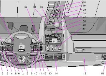
The pages in this section provide detailed descriptions of the vehicle's instruments and controls. Note that vehicles may be equipped differently, depending on special legal requirements.
1 Air vents 2 Headlights, parking lights 3 Instrument illumination 4 Rear fog light 5 Front fog lights (optional)
33
20
22
22
2216-17
23
41
26-28
23
33
4-6
33
51
20
29
32
21
30
31
127
33-35
23
316 Space for additional equipment 7 Space for additional equipment 8 Instruments 9 Stability Control System - STC (optional) 10 Electrically operated sun roof (optional) 11 Trip computer (optional) 12 Rear window demister/heated door mirrors 14 Air vents 15 Passenger side air bag (SRS) hatch 16 Air vents 17 Hood release 18 Turn signals, high/low beams, exterior courtesy lights Cruise control 19 Adjustable steering wheel 20 Windshield wiper/washer 21 Heated front seats (optional) 22 Auxiliary socket 23 Audio systems 24 Heating and ventilation controls 25 Hazard warning flashers 26 Ashtray 27 Coin holder 28 Shiftlock release button (automatic transmission only) 95
29 Gear selector shift positions 30 Winter mode selector 31 Parking brake 32 Horn/SRS 33 Trunk open control 34 Power window controls 35 Power mirror controls 36 Fuel filler open 37 Central locking button61-62
61-62
30
4-6
52
36
48
37
36Some of the items above are available on certain models only.
pg. 16 Instruments
1 Fuel gauge
The fuel tank holds approximately 17.9 US gal. (68 liters). When the warning light comes on there is approximately 1.8 US gal. (8 liters) of fuel remaining. See "Refueling" for further information. 2 Temperature gauge
Do not drive the car with the pointer in the red range. The pointer should be approximately midway on the gauge face when driving. If the pointer approaches the red range repeatedly, check coolant level. 3 Speedometer 4 Clock, ambient temperature sensor, trip
computer (certain models) 5 Odometer 6 Trip odometer
NOTE: Digital displays showing Clock, Trip Odometer and Odometer will go off 30 minutes after the ignition has been switched off. To view these displays again, turn the ignition key to position I. 7 Trip odometer reset button
Used for measuring shorter distances. The last digit indicates 1/10 mile/km. 8 Tachometer
Reads thousands of engine rpm. Do not drive for long with the needle in the red section. The engine has an inbuilt function preventing too high a rotation speed. When this function operates, you may discern some pulsation, which in that case is quite normal.
pg. 17 Indicator and warning lights
1 Turn signal, left
2 Turn signal, right
3 Cruise control
4 Low washer fluid level
If the lamp glows continuously when the engine is running, there is only about 1/2 - 1 US qt. remaining in the washer fluid reservoir.
5 Low fuel level
When the lamp glows, only about 1.8 US gals. (8 liters) of fuel remain. If the ignition is switched on while refuelling, the gauge may read inaccurately for up to 25 minutes.
6 Rear fog light
7 High beams
8 Trunk/tailgate open
9 Bulb failure warning sensor
10 (Not in use)
11 Electronic Throttle System (ETS)
12 SRS
13 Generator not charging
14 Low engine oil pressure
15 Brake warning light
16 Parking brake applied
17 ABS-system
18 Transmission mode: Indicates "W" if winter/wet driving mode is active, or indicates currently selected low gear.
19 Low coolant level
20 Stability and Traction Control (STC) System (option)
21 Malfunction indicator lamp
(See page 18 for more information)
22 Service reminder indicator
pg. 18 Warning lights
The warning lights described on pages 18 and 19 should never stay on when driving
When the ignition key is turned on and before the engine starts, all of the warning lights should go on to test the function of the bulbs. Should a light not go off after the engine has started, the system indicated should be inspected. However, the parking brake reminder light will not go off until the parking brake has been fully released.
Generator warning light
If the light comes on while the engine is running, have the charging system checked.
Malfunction indicator lamp
If the lamp comes on (or stays on after the vehicle has started), the engine diagnostic system has detected a possible fault in the emission control system. Although driveability may not be affected, see an authorized Volvo retailer as soon as possible for inspection.
NOTE: If the fuel filler cap is not closed tightly or if the engine is running when the car is refueled, the Malfunction Indicator Lamp may indicate a fault. However, your vehicle's performance will not be affected. Use only Volvo original or approved fuel filler caps.
Oil pressure warning light
If the light comes on while driving, stop the car and then stop the engine immediately and check the engine oil level. See page 112. If the light stays on after restart, have the car towed to the nearest authorized Volvo retailer. After hard driving, the light may come on occasionally when the engine is idling. This is normal, provided it goes off when the engine speed is increased.
Fault in ETC (Electronic Throttle Control system)
If this lamp comes on, there is a fault in the engine control system and driveability will be affected. Switch the ignition off and then on again. If the light remains on, the system should be inspected by an authorized Volvo retailer.
Cruise Control
This light will be on when cruise control is engaged. Cruise control will automatically disengage when the ignition is switched off.
Brake failure warning light
If the light comes on while driving or braking, stop immediately, open the hood and check the brake fluid level in the reservoir. See page 117 for reservoir position.
Canadian models are equipped with this warning light: WARNING! If the fluid level is below the MIN mark in either section of the reservoir: DO NOT DRIVE. Tow the car to a Volvo retailer and have the brake system checked and any leakage repaired.
Parking brake reminder light
This light will be on when the parking brake (hand brake) is applied. The parking brake lever is situated between the front seats.
Canadian models are equipped with this warning light:
pg. 19 Warning lights
STC disengaged (option)
The indicator light in the instrument panel will be ON when you have switched the Stability and Traction Control system (STC) OFF using the button on the dashboard (see page 23). The light will also come on if there is a fault in the STC system or to indicate that the brakes have overheated. The light will go out when the brake temperature returns to normal.
The symbol will flash when STC is actively regulating power to the drive wheels. Normal power may be reduced at this time. This is normal as power is momentarily reduced to help keep the drive wheels from losing traction and spinning.
Anti-lock Brake system (ABS)
If the warning lamp lights up there is a malfunction of the ABS system (the standard braking system will however function). The vehicle should be driven to a Volvo retailer for inspection.
See page 69 for additional information.
Canadian models are equipped with this warning light:
Coolant level sensor
If this light comes on while driving, the coolant level is low. The coolant level in the expansion tank should be checked immediately and topped up if necessary. The cooling system should be inspected by an authorized Volvo retailer.
Mode "W" engaged
The lamp will light up when the Winter/Wet starting mode is engaged or if gears "4,3" or "L" are selected.
If the warning lamp begins to flash, this means that there is a fault in the automatic gearbox. Contact Your Volvo retailer.
Supplemental Restraint System (SRS)
If the light comes on (or stays on after the vehicle has started), the SRS diagnostic system has detected a fault. Drive to an authorized Volvo retailer for an inspection of the system. See the SRS section for more information.
Service reminder indicator
This light will come on at 7,500 mile (12,000 km) intervals, after 750 hours of driving or after 12 months, whichever occurs first. It is a reminder to the driver that the service interval has been exceeded. The light will stay on for 2
minutes after start until reset by the servicing retailer.Bulb failure warning light
The light will come on if any of the following bulbs are defective:
· one of the low beam headlights
· one of the tail lights
· one of the brake lights when the brake pedal is depressed.
Check the fuse and bulb. See sections "Replacing bulbs" and "fuses.
Should the warning light come on after a defective outside bulb has been replaced, the corresponding bulb on the other side of the car should also be replaced.
Contents | Top of Page
2 0 0 1 VOLVO
C70
Chapter 3 - Body and interior
pg. 39 Body and interior
The seats, sun roof, mirrors, etc. are described on the following pages.
Storage compartments 40
Sun roof 41
Keys, doors and locks 42
Remote keyless entry system 43
Alarm 44
Front seats 46
Rear/side view mirrors 48
Interior lights, Vanity mirrors 49
Long load storage 50
Hood 51
Opening the trunk 52
Trunk light, Spare tire, Jack 53
Securing cargo, Avoiding battery drain 54pg. 40 Storage compartments
WARNING! Packages on the rear window shelf can obscure vision and may become dangerous projectiles in the event of a sudden stop or an accident.
1 Glove compartment
2 Shelf under glove compartment
3 Coin holder
4 Compartment in door
5 Pocket on rear of front seat
6 Compartment between front seats
7 Cup holder
pg. 41 Sun roof (option)
Electrically operated sun roof
The switch for operating the sun roof is located on the instrument panel. The starting
(ignition) key must first be turned to the drive position (position II). The sun roof is also equipped with a one-touch,
AUTO-open function.
· AUTO-open: Press the lower section of the switch once to automatically open the sun roof.
The AUTO-open function can be stopped at any time by pressing the switch.
· To close the sun roof: Depress the upper section of the switch until the sun roof has closed completely.
· To open the rear edge of the sun roof (ventilation position): With the sun roof closed, depress the upper section of the switch. To close, depress the lower section of the switch until the sun roof has closed completely.
· To slide open the sun roof : Depress the lower section of the switch until the sun roof has opened to the position you prefer or until it reaches its final position and stops automatically.
Sun visor: The sun roof also features a sliding sun visor. The visor slides back automatically when the sun roof is opened and also slides back slightly when the sun roof is opened to the ventilation position. The visor must be closed manually.
CAUTION: Do not close the sun visor when the sun roof is in the ventilation position as this could damage the mechanism. NOTE:
The electrically operated sun roof has an overload protecting circuit breaker (fuse no. 37) which is activated when an object blocks the sun roof. Should this occur, remove the object and wait 20 seconds for the circuit breaker to reset. The sun roof should then function normally. Also check fuse no. 35. WARNING! The sun roof must never be obstructed in any way when in operation.
pg. 42 Keys, doors and locks
Doors and locks
Your car is equipped with a central locking system. The key, used on the driver's door, the remote control or central locking button, will lock/unlock both doors and the trunk.
· Turn the key once to unlock the driver's door only.
· Turn the key again (within 10 seconds) to unlock both doors and the trunk. One turn with the key towards lock in the drivers door locks both doors and the trunk.
· Use the switch on the front door armrests to lock/unlock the car from the inside. Check the action of the button on the other door to verify its function (lock/ unlock). WARNING! If the doors are locked while driving, this may hinder rapid access to the occupants of the car in the event of an accident. (Also see information on "Child safety locks").
NOTE:
· If a door is not closed completely, the courtesy lights will stay on and a chime will sound until the door is closed.
· As an added anti-theft measure, new keys have been developed which may take slightly longer to copy or replace if the original keys are misplaced. Duplicate keys may be ordered from your Volvo retailer.
Immobilizer (start inhibitor)
Each of the keys supplied with your car contains a coded transmitter and receiver (transponder). The code in the key is transmitted to an antenna in the ignition switch where it is compared to the code stored in the start inhibitor module. The car can only be started if a properly coded key is used.
If you misplace a key, take the other keys to an authorized Volvo retailer. The existing code in the start inhibitor module and all the keys will be erased as an antitheft measure and a new code will be programmed in.
NOTE:
Not more than one of the keys for your car should be kept on the same key ring. This could cause conflicting signals to be transmitted to the ignition switch, making it impossible to start the car.
This device complies with part 15 of the FCC rules. Operation is subject to the following condition: (1) This device may not cause harmful interference, and (2) this device must accept any interference received, including interference that may cause undesired operation.
This key operates the driver's door and the ignition switch/steering wheel lock. The key number codes are stamped on a separate tag supplied with the keys. This tag should be separated from the key ring and kept in a safe place.
Contents | Top of Page
2 0 0 1 VOLVO
C70
Chapter 4 - Starting and driving
pg. 55 Starting and driving
This section on starting and driving contains items such as starting the engine, operating the gear selector, towing, trailers, etc.
Fuel requirements, Refueling 56-57
Driving economy 58
Starting the engine 59
Manual transmission 60
Automatic transmission 61
Points to remember 63
Emergency towing 66
Vehicle towing information 67
Jump starting 68
Brake system 69-70
Trailer towing 71
Winter driving 72pg. 56 Fuel requirements
NOTE ENGINE OIL:
Although some oil consumption occurs during normal engine operation, more oil is consumed when the engine is new as the internal parts generate higher friction while wearingin to each other. From the time the engine is new until the first service is performed, the oil consumption could be higher than normal. For this reason, it is especially important to check the oil every time you refuel your car during this period. See page 112.
In general, the rate of oil consumption depends on such factors as: engine temperature, length of trip, driving conditions, oil viscosity and quality, engine speed and acceleration/deceleration.
Checking your engine oil level each time the car is refueled is one of the most important items you can perform to help keep your car in good running order. Deposit control gasoline (detergent additives)
Volvo recommends the use of gasoline containing deposit control additives. These additives have shown to be efficient in keeping injectors and intake valves clean. Consistent use of deposit control gasolines will help ensure good driveability and fuel economy. If you are not sure whether the gasoline contains deposit control additives, check with the service station operator. Unleaded fuel
Each Volvo has a three-way catalytic converter and must use only unleaded gasoline. U.S. and Canadian regulations require that pumps delivering unleaded gasoline be labelled "UNLEADED". Only these pumps have nozzles which fit your car's filler inlet. It is unlawful to dispense leaded fuel into a vehicle labelled "unleaded gasoline only". Leaded gasoline damages the three-way catalytic converter and the heated oxygen sensor system. Repeated use of leaded gasoline will lessen the effectiveness of the emission control system and could result in loss of emission warranty coverage. State and local vehicle inspection programs will make detection of misfueling easier, possibly resulting in emission test failure for misfueled vehicles.
NOTE: Some U.S. and Canadian gasolines contain an octane enhancing additive called methly-cyclopentadienyl manganese tricarbonyl (MMT). If such fuels are used, your Emission Control System performance may be affected, and the Malfunction Indicator Lamp located on your instrument panel may light. If this occurs, please return your vehicle to an authorized Volvo retailer for service.
pg. 57 Fuel requirements, Refueling
Octane rating
Volvo engines are designed for optimum performance on unleaded premium gasoline with an octane rating. AKI of 91, or above. AKI (ANTI KNOCK INDEX) is an average of the Research Octane Number, RON, and the Motor Octane Number, MON. (RON + MON/2).
The minimum octane requirement is AKI 87 (RON 91). Gasoline containing alcohol and ethers