- 2014 Toyota Tacoma Owners Manuals
- Toyota Tacoma Owners Manuals
- 2005 Toyota Tacoma Owners Manuals
- Toyota Tacoma Owners Manuals
- 2000 Toyota Tacoma Owners Manuals
- Toyota Tacoma Owners Manuals
- 2007 Toyota Tacoma Owners Manuals
- Toyota Tacoma Owners Manuals
- 2016 Toyota Tacoma Owners Manuals
- Toyota Tacoma Owners Manuals
- 2006 Toyota Tacoma Owners Manuals
- Toyota Tacoma Owners Manuals
- 2008 Toyota Tacoma Owners Manuals
- Toyota Tacoma Owners Manuals
- 2009 Toyota Tacoma Owners Manuals
- Toyota Tacoma Owners Manuals
- 2015 Toyota Tacoma Owners Manuals
- Toyota Tacoma Owners Manuals
- 2001 Toyota Tacoma Owners Manuals
- Toyota Tacoma Owners Manuals
- 2012 Toyota Tacoma Owners Manuals
- Toyota Tacoma Owners Manuals
- 2004 Toyota Tacoma Owners Manuals
- Toyota Tacoma Owners Manuals
- 2011 Toyota Tacoma Owners Manuals
- Toyota Tacoma Owners Manuals
- 2003 Toyota Tacoma Owners Manuals
- Toyota Tacoma Owners Manuals
- 2002 Toyota Tacoma Owners Manuals
- Toyota Tacoma Owners Manuals
- 2010 Toyota Tacoma Owners Manuals
- Toyota Tacoma Owners Manuals
- Download PDF Manual
-
2008 TACOMA from Apr. ’08 Prod. (OM35898U)
08 02.19
Tire related term
Occupant distribution
Production options weight
Rim
Rim diameter (Wheel diameter) Rim size designation Rim type designation Rim width Vehicle capacity weight (Total load capacity)
Vehicle maximum load on the tire
Vehicle normal load on the tire
Meaning
distribution of occupants in a vehicle as specified in the third column of Table 1 that follows the combined weight of those installed regular production options weighing over 2.3 kg (5 lb.) in excess of those standard items which they replace, not pre- viously considered in curb weight or accessory weight, including heavy duty brakes, ride levelers, roof rack, heavy duty battery, and special trim a metal support for a tire or a tire and tube assembly upon which the tire beads are seated nominal diameter of the bead seat rim diameter and width the industry of manufacturer’s designation for a rim by style or code nominal distance between rim flanges the rated cargo and luggage load plus 68 kg (150 lb.) times the vehicle’s desig- nated seating capacity the load on an individual tire that is determined by distributing to each axle its share of the maximum loaded vehicle weight and dividing by two the load on an individual tire that is determined by distributing to each axle its share of the curb weight, accessory weight, and normal occupant weight (distributed in accordance with Table 1 that follows) and dividing by two
2008 TACOMA from Apr. ’08 Prod. (OM35898U)
293
08 02.19
Tire related term
Meaning
Weather side
Bead
Bead separation
Bias ply tire
Carcass
Chunking Cord Cord separation
Cracking
CT
Extra load tire
294
the surface area of the rim not covered by the inflated tire the part of the tire that is made of steel wires, wrapped or reinforced by ply cords and that is shaped to fit the rim a breakdown of the bond between components in the bead a pneumatic tire in which the ply cords that extend to the beads are laid at alternate angles substantially less than 90 degrees to the centerline of the tread the tire structure, except tread and sidewall rubber which, when inflated, bears the load the breaking away of pieces of the tread sidewall the strands forming the plies in the tire the parting of cords from adjacent rubber compounds any parting within the tread, sidewall, or innerliner of the tire extending to cord material a pneumatic tire with an inverted flange tire and rim system in which the rim is designed with rim flanges pointed radially inward and the tire is designed to fit on the underside of the rim in a manner that encloses the rim flanges inside the air cavity of the tire a tire designed to operate at higher loads and at higher inflation pressures than the corresponding standard tire
2008 TACOMA from Apr. ’08 Prod. (OM35898U)
08 02.19
Tire related term
Meaning
Groove
Innerliner
Innerliner separation
Intended outboard sidewall
Light truck (LT) tire
Load rating
Maximum load rating
the space between two adjacent tread ribs the layer(s) forming the inside surface of a tubeless tire that contains the inflat- ing medium within the tire the parting of the innerliner from cord material in the carcass (A) the sidewall that contains a whitewall, bears white lettering or bears
manufacturer, brand, and/or model name molding that is higher or deeper than the same molding on the other sidewall of the tire, or
(B) the outward facing sidewall of an asymmetrical tire that has a particular
side that must always face outward when mounted on a vehicle
a tire designated by its manufacturer as primarily intended for use on lightweight trucks or multipurpose passenger vehicles the maximum load that a tire is rated to carry for a given inflation pressure the load rating for a tire at the maximum permissible inflation pressure for that tire
Maximum permissible inflation pres- sure Measuring rim
Open splice
the maximum cold inflation pressure to which a tire may be inflated
the rim on which a tire is fitted for physical dimension requirements any parting at any junction of tread, sidewall, or innerliner that extends to cord material
2008 TACOMA from Apr. ’08 Prod. (OM35898U)
295
08 02.19
Tire related term
Meaning
Outer diameter
Overall width
Passenger car tire
Ply Ply separation
Pneumatic tire
Radial ply tire
Reinforced tire
Section width
Sidewall Sidewall separation
296
the overall diameter of an inflated new tire the linear distance between the exteriors of the sidewalls of an inflated tire, including elevations due to labeling, decorations, or protective bands or ribs a tire intended for use on passenger cars, multipurpose passenger vehicles, and trucks, that have a gross vehicle weight rating (GVWR) of 10,000 lb. or less a layer of rubber−coated parallel cords a parting of rubber compound between adjacent plies a mechanical device made of rubber, chemicals, fabric and steel or other mate- rials, that, when mounted on an automotive wheel, provides the traction and contains the gas or fluid that sustains the load a pneumatic tire in which the ply cords that extend to the beads are laid at substantially 90 degrees to the centerline of the tread a tire designed to operate at higher loads and at higher inflation pressures than the corresponding standard tire the linear distance between the exteriors of the sidewalls of an inflated tire, excluding elevations due to labeling, decoration, or protective bands that portion of a tire between the tread and bead the parting of the rubber compound from the cord material in the sidewall
2008 TACOMA from Apr. ’08 Prod. (OM35898U)
08 02.19
Tire related term
Meaning
Snow tire
Test rim
Tread Tread rib Tread separation
Treadwear indicators (TWI)
Wheel−holding fixture
a tire that attains a traction index equal to or greater than 110, compared to the ASTM E−1136 Standard Reference Test Tire, when using the snow traction test as described in ASTM F−1805−00, Standard Test Method for Single Wheel Driving Traction in a Straight Line on Snow−and Ice−Covered Surfaces, and which is marked with an Alpine Symbol ( ) on at least one sidewall the rim on which a tire is fitted for testing, and may be any rim listed as appropri- ate for use with that tire that portion of a tire that comes into contact with the road a tread section running circumferentially around a tire pulling away of the tread from the tire carcass the projections within the principal grooves designed to give a visual indication of the degrees of wear of the tread the fixture used to hold the wheel and tire assembly securely during testing
2008 TACOMA from Apr. ’08 Prod. (OM35898U)
297
08 02.19
Table 1—Occupant loading and distribution for vehicle normal load for various designated seating capacities
Designated seating capacity,
number of occupants
Vehicle normal load, number of
occupants
2 through 4
5 through 1011 through 15
16 through 20
Occupant distribution in a normally
loaded vehicle
2 in front 2 in front, 1 in second seat 2 in front, 1 in second seat, 1 in third seat, 1 in fourth seat 2 in front, 2 in second seat, 2 in third seat, 1 in fourth seat
298
2008 TACOMA from Apr. ’08 Prod. (OM35898U)
08 02.19
Vehicle load limits Vehicle load limits include total load capacity, seating capacity, towing capacity and cargo capacity. Follow the load limits shown below. Total load capacity and seating capacity are also described on the tire and loading information label. For location of the tire and loading information label, see “Checking tire inflation pressure” on page 376. Total load capacity: Total load capacity means combined weight of occupants, cargo and luggage. Tongue load is included when trailer towing. For the total load capacity about your vehicle, see “Vehicle capacity weight” on page 402
in Section 8.Seating capacity:
Regular cab models
With separate type seats
With bench type seat
Total 2
Total 3
Access cab models
Total 2+2 (Front 2, Rear Temporary 2)
Double cab models
Total 5 (Front 2, Rear 3)
Seating capacity means the maximum number of occupants whose esti- mated average weight is 68 kg (150
lb.) per person. Depending on the weight of each person, the seating ca- pacity given may exceed the total load capacity.NOTICE
Even if the number of occupants are within the seating capacity, do not exceed the total load ca- pacity.
Towing capacity: Towing capacity means the maximum gross trailer weight (trailer weight plus its cargo weight) that your vehicle is able to tow. For the towing capacity about your vehicle, see “Towing ca- pacity” on page 405 in Section 8. Cargo capacity Cargo capacity may increase or de- crease depending on the size (weight) and the number of occupants. For de- tails, see “Capacity and distribution” that follows.
CAUTION
Do not apply the load more than each load limit. That may cause not only damage to the tires, but also deterioration to the steering ability and braking ability, which may cause an accident.
2008 TACOMA from Apr. ’08 Prod. (OM35898U)
299
08 02.19
Cargo and luggage— —Stowage precautions When stowing cargo and luggage in the vehicle, observe the following: D Put cargo and luggage in the rear deck when at all possible. Be sure all items are secured in place.
D Be careful to keep the vehicle bal- anced. Locating the weight as far forward as possible helps maintain balance.
D For better fuel economy, do not
carry unneeded weight.
CAUTION
D To prevent cargo and luggage from sliding forward during braking, do not stack anything behind the front seats higher than the seatbacks (access cab and double cab models). Keep cargo and low, as close to the floor as possible.
luggage
300
D Never allow anyone to ride in the rear deck. It is not designed for passengers. They should ride in their seats with their seat belts properly fastened. Otherwise, they are much more likely to suffer death or serious bodily injury, in the event of sudden braking or a collision. D Do not drive with objects left on top of the instrument panel. They may interfere with the driver’s field of view. Or they may move during sharp vehicle acceleration or turning, and im- pair the driver’s control of the vehicle. In an accident they may injure the vehicle occu- pants.
—Capacity and distribution Cargo capacity depends on the to- tal weight of the occupants. (Cargo capacity) = (Total load capac- ity) – (Total weight of occupants) Steps Load Limit— (1) Locate
for Determining Correct
the statement
“The combined weight of occupants and cargo should never exceed XXX kg or XXX lbs.” on your vehicle’s placard.
(2) Determine the combined weight of the driver and passengers that will be riding in your vehicle.
(3) Subtract the combined weight of the driver and passengers from XXX kg or XXX lbs.
(4) The resulting figure equals the available amount of cargo and luggage load capacity. For exam- ple, if the “XXX” amount equals 1400 lbs. and there will be five 150 lb passengers in your ve- hicle, the amount of available cargo and luggage load capacity is lbs. (1400–750
(5x150)=650 lbs.)650
2008 TACOMA from Apr. ’08 Prod. (OM35898U)
08 02.19
(5) Determine the combined weight luggage and cargo being of the vehicle. That loaded on weight may not safely exceed the available cargo and luggage load capacity calculated in Step 4. If your vehicle will be towing a trailer, load from your trailer will be transferred to your vehicle. Consult this manual to determine how this reduces the available cargo and luggage load capacity of your vehicle.
(6)
For details about trailer towing, see “Trailer towing” on page 310 in Sec- tion 3.
SU21020
Cargo capacity
Total load capacity
Example on Your Vehicle In case that 2 people with the com- bined weight of A kg (lb.) are riding in your vehicle with the total load ca- pacity of B kg (lb.), the available amount of cargo and luggage load ca- pacity will be C kg (lb.) as follows: B kg (lb.) – A kg (lb.) = C kg (lb.) From this condition, if 3 more passen- gers with the combined weight of D kg (lb.) get on, the available cargo and luggage load will be reduced E kg (lb.) as follows: C kg (lb.) – D kg (lb.) = E kg (lb.)
As shown in the above example, if the number of occupants increases, the cargo and luggage load equaling the combined weight of occupants who got on later must be reduced. In other words, if the increase in the number of occupants causes the excess of the total load capacity (combined weight of occupants plus cargo and luggage load), you have to reduce the cargo and luggage on your vehicle. For details about total load capacity, see “Vehicle load limits” on page 299
in this Section.CAUTION
Even if the total load of occu- pant’s weight and the cargo load is less than the total load capac- ity, do not apply the load uneven- ly. That may cause not only dam- age to the tire but also deteriora- tion to the steering ability due to unbalance of the vehicle, causing an accident.
2008 TACOMA from Apr. ’08 Prod. (OM35898U)
301
08 02.19
Types of tires Determine what kind of tires your vehicle is originally equipped with. 1. Summer tires Summer tires are high−speed capabil- ity tires best suited to highway driving under dry conditions. Since summer tires do not have the same traction performance as snow tires, summer tires are inadequate for driving on snow−covered or icy roads. For driving on snow−covered or icy roads, we recommend using snow tires. If installing snow tires, be sure to replace all four tires. 2. All season tires All season tires are designed to pro- vide better traction in snow and to be adequate for driving in most winter conditions, as well as for use all year round.
traction
All season tires, however, do not have adequate performance compared with snow tires in heavy or loose snow. Also, all season tires fall short in acceleration and handling performance compared with summer tires in highway driving. The details about how to distinguish summer tires from all season tires are described on page 287.
CAUTION
D Do not mix summer and all sea- son tires on your vehicle as this can cause dangerous han- dling characteristics, resulting in loss of control.
D Do not use tires other than the manufacture’s designated tires, and never mix tires or wheels of the sizes different from the originals.
302
2008 TACOMA from Apr. ’08 Prod. (OM35898U)
2008
Quick Reference Guide2008
TacomaThis Quick Reference Guide is a summary of basic vehicle operations. It contains brief descriptions of fundamental operations so you can locate and use the vehicle’s main equipment quickly and easily. The Quick Reference Guide is not intended as a substitute for the Owner’s Manual located in your vehicle’s glove box. We strongly encourage you to review the Owner’s Manual and supplementary manuals so you will have a better understanding of your vehicle’s capabilities and limitations.
Your dealership and the entire staff of Toyota Motor Sales, U.S.A., Inc. wish you many years of satisfied driving in your new Tacoma.
! A word about safe vehicle operations This Quick Reference Guide is not a full description of Tacoma operations. Every Tacoma owner should review the Owner’s Manual that accompanies this vehicle. Pay special attention to the boxed “ ” information highlighted throughout the Owner’s Manual. Each box contains safe operating instructions to help you avoid injury or equipment malfunction. All information in this Quick Reference Guide is current at the time of printing. Toyota reserves the right to make changes at any time without notice.
INDEX
Item
Page no.
OVERVIEW
Engine maintenance Fuel tank door release and cap Hood release Indicator symbols Instrument cluster Instrument panel Keyless entry
FEATURES/OPERATIONS
Accessory meter Air Conditioning/Heating Audio Auto LSD (Auto Limited Slip Differential) Automatic Transmission Bottle holders Clock Cruise control Cup holders Door locks-Power Four-wheel drive Lights & turn signals Light control-Instrument panel Manual Transmission Parking brake Power outlets Rear differential lock Seat adjustments-Front Seats-Head restraints Tilt and telescopic steering wheel Windows-Power Windshield wipers & washers
4-5
2-314-15
16
1619
18
10
17
18
19
11
19
13
13
17
10
10
12
12SAFETY AND EMERGENCY FEATURES
Doors-Child safety locks Seat belts Seat belts-Shoulder belt anchor Spare tire & tools Tire Pressure Warning System reset
21
20
20
21
20OVERVIEW
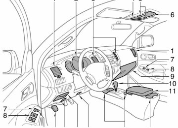
Instrument panel
Steering wheel controls (if equipped)
Volume control buttons (for audio) “ ” buttons (for audio) >> “MODE” button (for audio) Front fog light switch1
Rear differential lock switch1
115V AC Power outlet ON/OFF switch1
Instrument panel light control Headlight and turn signal controls Wiper and washer controls Two-wheel/Four-wheel drive selector1
Audio system Clock Theft deterrent system/Engine immobilizer indicator1
Front passenger seat belt reminder Front passenger occupant classification indicator1
or front passenger airbag ON/OFF indicator1O
Front passenger airbag manual ON/OFF switch1
Air Conditioning controls 12V DC Power outlet Emergency flasher switch 12V DC Power outlet/Cigarette lighter Parking brake lever (stick type)2
Cruise control1
Engine switch Roll sensing curtain shield airbags OFF switch “DAC” (Downhill Assist Control) button1 or clutch start cancel switch1
“VSC OFF” switch1
Power rearview mirror control switches11 If equipped 2 Manual Transmission only.
(Automatic Transmissions are equipped with a parking brake pedal.)
OVERVIEW
Instrument cluster
Tachometer Speedometer Odometer and two trip meters Service indicator and reminder Engine coolant temperature Fuel gauge Trip meter reset knob Gear shift position indicator*
* If equipped
Indicator symbols
Brake system warning1
Driver/Front passenger seat belt reminder1
Charging system warning1
Front passenger occupant classification indicator Low engine oil pressure warning1Malfunction/Check Engine indicator1
Engine oil replacement reminder1
Open door warning1
1 For details, refer to “Service reminder indicators and warning
buzzers,” Section 1-6, 2008 Owner’s Manual.
2 If this light flashes, refer to “Four-wheel drive system,” Section
1-7, 2008 Owner’s Manual.
3 If this light flashes, refer to “Rear differential lock system,”
Airbag SRS warning1
Automatic Transmission fluid temperature warning1
Low Tire Pressure Warning1
Theft deterrent/Engine immobilizer system indicator Roll Sensing Curtain shield Airbags off indicator5Headlight low beam indicator
Headlight high beam indicator
Turn signal indicator
Automatic Transmission indicator (5-speed)/(4-speed) Four-wheel drive indicator2
Low speed four-wheel drive indicator2
Rear differential lock indicator3
Slip indicator Vehicle Stability Control “OFF” indicator warning1
Downhill assist control indicator“AUTO LSD” indicator
Cruise control indicator4
Anti-lock Brake System warning1
Section 1-7, 2008 Owner’s Manual.
4 If this light flashes, refer to “Cruise control,” Section 1-7, 2008
Owner’s Manual.
5 If this light flashes, refer to “Roll sensing of curtain shield
airbags off switch,” Section 1-3, 2008 Owner’s Manual.
OVERVIEW
Keyless entry Locking operation Push
Unlocking operation Push ONCE: Driver door
TWICE: All doors
NOTE: After unlocking, if a door is not opened within 30 seconds, all doors will relock for safety. Panic button Push and hold
Fuel tank door release and cap
Turn
Pull
NOTE: Tighten until one click is heard. If the cap is not tightened enough, Check Engine “ ” indicator may illuminate.
Hood release
Pull up latch and raise hood
Pull
Engine maintenance 4 cylinder (2TR-FE) engine
6 cylinder (1GR-FE) engine
Windshield washer fluid tank Engine coolant reservoir Engine oil filler cap Power steering fluid reservoir Engine oil level dipstick
Note: Regularly scheduled maintenance, including
oil changes, will help extend the life of your vehicle and maintain performance. Please refer to the “Owner’s Warranty Information Booklet,” “Scheduled Maintenance Guide” or “Owner’s Manual Supplement.”
FEATURES/OPERATIONS
Automatic Transmission 5-speed models
Park1
Park1
Reverse Reverse Neutral Neutral Drive Drive Fourth gear Fourth gear Third gear Third gear Second gear Second gear First gear First gear4-speed models
Park1
Reverse Neutral Drive Third gear Second gear First gear1 The engine switch must be ON, and the brake
pedal depressed to shift from “Park.”
Downshifting increases power going uphill, or provides engine braking downhill. For best fuel economy during normal driving conditions, always drive with the shift lever in the “D” position.
Manual Transmission Tacoma is available with optional 5-speed or 6-speed Manual Transmission. For safety, the engine will not start unless the clutch pedal is FULLY depressed. Refer to the Owner’s Manual for more details.
Four-wheel drive (if equipped)
Turn
Turn
Push and turn
High speed (2WD) High speed (4WD) Shift when speed is below 62 mph. Low speed (4WD) Shift into neutral while stopped, or depress clutch pedal at speeds below 2 mph.
For best fuel economy and performance under normal driving conditions, keep in “H2” position.
Tilt and telescopic steering wheel
Angle
Length
Lock release lever
Hold wheel, push lever down, set angle and length, and return lever. Note: Do not attempt to adjust while the vehicle
is in motion.
FEATURES/OPERATIONS
Seat adjustments-Front Separate seat
Bench seat
Position Lumbar support* Seatback angle * If equipped
Seats-Head restraints Separate seats-Front
Bench seat-Front
(2)
(1)
Lock release button
Lock release button
Clock
H- Hour set M- Minute set
10
Lights & turn signals Headlights
Headlights
Parking lights
High beam
Low beam
High beam flasher
-Daytime Running Light system (DRL) Automatically turns on the turn signal lights at a reduced intensity. -Automatic light cut off system Automatically turns lights off when driver’s door is opened with the engine switch in the “ACC” or “LOCK” position.
Front fog lights (if equipped)
Push
Front fog lights come on only when the headlights are on low beam. Turn signals
Right turn
Lane change
Lane change
Left turn
11
FEATURES/OPERATIONS
Windshield wipers & washers With intermittent wiper
Adjust interval
Single wipe
Pull to wash and wipe
Without intermittent wiper
Pull to wash and wipe
Interval wipe
Slow
Fast
Single wipe
Slow
Fast
Windows-Power (if equipped) Access cab models Driver side
Window lock switch
Up
Down
Up
Down
Double cab models Driver side
Up
Down
Window lock switch
Up Down
Automatic down operation (driver side only) Push the switch completely down and release to fully open. To stop window midway, lightly pull up on the switch. Window lock switch Deactivates all passenger windows. Driver’s window remains operable.
12
Parking brake Automatic Transmission Set: Depress Release: Depress again
Manual Transmission Set
Power outlets 12V DC
Release
(2) Turn and push in lever
(1) Push button
Key must be in the “ACC” or “ON” position to be used. 115V AC (if equipped)
ON/OFF switch
Green indicator
Yellow indicator
Right side of bed The engine must be running for use.
Push
Yellow Light Only Max Capacity 115V AC/100W Green & Yellow Lights Max Capacity 115V AC/400W Refer to the Owner’s Manual for more details.
13
FEATURES/OPERATIONS
Audio
Type 1
Eject CD
Preset buttons - functions in other modes indicated below number
View CD information
Push to adjust tone & balance
Station/CD track scan
Load CD(s)
View radio and CD information
View genre with RDS system
Push to turn ON/OFF Seek station/ CD track select
Mode
Type 2 additional functions
Type 3 additional functions
Traffic information
14
CD PLAYER To scan tracks on a disc Push and hold “SCAN.” Push again to hold selection. CD changer (Types 2 and 3 only) -To load one disc Push “LOAD” and insert one disc. -To load multiple discs Push and hold “LOAD” until you hear a beep. Insert one disc. Shutter will close and then re-open for next disc. RADIO To preset stations Tune in the desired station and hold down a preset button (1-6) until you hear a beep. Push desired preset button (1-6) to select. To scan stations Push and hold “SCAN” to scan preset stations. Push again to hold selection. RDS (Radio Data System - FM, Type 3 only) -Push “TYPE” to select station genre. -Push steering wheel switches “ ” or “ ,” or preset button (1-6) to select stations within genre. -Push “TEXT” to receive information transmitted from radio stations. Steering wheel switches (if equipped)
> >
“ - + ” Volume control “ ” >> -In radio mode Push to select a preset station; push and hold to seek the next strong station. -In CD mode Push to skip up or down to the next/previous track. “MODE” Push to turn audio ON and select an audio mode. Push and hold to turn the audio system “OFF.”
15
FEATURES/OPERATIONS
Air Conditioning (if equipped)/Heating
Fan speed Temperature Airflow vent In “ ” or “ ” mode, use fresh air (“ ” indicator “OFF”) to reduce window fogging. Fresh or recirculated cabin air Air Conditioning ON/OFF (if equipped) Use fresh air to quickly cool interior, then change to recirculate for cooler air.
Accessory meter (if equipped)
E/M (English/Metric) button To select Fahrenheit or Celsius. Compass Outside temperature display
16
Cruise control (if equipped) Turning system ON/OFF
System ON/OFF
Functions
Cancel1
Resume2/Increase speed
Set/Decrease speed
1 The set speed may also be cancelled by depressing the brake pedal. 2 The set speed may be resumed once vehicle speed
exceeds 25 mph. Rear differential lock (if equipped)
Rear differential Lock/Unlock
Use ONLY when wheel spinning occurs in a ditch, or on slippery or unpaved surfaces. DO NOT USE THE REAR DIFFERENTIAL LOCK IN CONDITIONS OTHER THAN SPECIFIED IN THE OWNER’S MANUAL. UNLOCK THE DIFFERENTIAL ONCE THE VEHICLE MOVES OUT OF THE TROUBLE SPOT. Refer to your Owner’s Manual for complete details on this system before attempting to use it.
17
FEATURES/OPERATIONS
Bottle holders Front door
Center console-Rear
Rear door (double cab only)
Cup holders Front console Bench seat
Separate seats (Automatic Transmission)
Center console Separate seats (Automatic Transmission)
Separate seats (Manual Transmission)
18
Door locks-Power (if equipped)
Lock
Unlock
Auto LSD (Auto Limited Slip Differential)(if equipped)
VSC OFF
Briefly push the “VSC OFF” switch to activate Auto LSD. To deactivate, briefly push the switch again. Note: ONLY works in 2-wheel drive at speeds
under 62 mph. Should ONLY be used when wheel spinning occurs on slippery or unpaved surfaces.
Refer to the Owner‘s Manual for more details on this system before attempting to use it. Light control-Instrument panel
Brightness control
19
SAFETY AND EMERGENCY FEATURES Seat belts
Take up slack Too high
Keep as low on hips as possible
If belt is fully extended, then retracted even slightly, it cannot be re-extended beyond that point, unless fully retracted again. This feature is used to help hold child restraint systems securely.
To find more information about seat belts, and how to install a child restraint system, refer to the Owner's Manual. Seat belts-Shoulder belt anchor
Push up, or squeeze lock release to lower
Tire Pressure Warning System reset
If tire pressure becomes critically low on any of the tires (including spare), indicator comes on. Pushing “ SET” button should not turn off the light. Correctly adjusting tire inflation will turn off the light after a few minutes. After replacing/rotating tire or wheels, the system must be initialized. Refer to the Owner’s Manual for details on system reset initialization.
20
Doors-Child safety locks (double cab only)
Rear door
Moving the lever to “LOCK” will allow the door to be opened only from the outside.
Spare tire & tools Tool location Regular cab models -behind the seatback
Double cab models -under the rear seat
Jack
Tool bag
Tool bag
Front
Jack
Access cab models -under the rear seat
Tool bag
Front
Jack
Removing the spare tire (1)
(2)
(3)
(1) Assemble the jack handle. (2) Insert the jack handle end into the lowering
screw.
(3) Turn the jack handle counterclockwise. Refer to the Owner’s Manual for tire changing and jack positioning procedures.
21
Customer Experience Center
1-800-331-4331
MN 00505-QRG08-TAC Printed in the USA 7/07
08 02.19
SECTION 3
STARTING AND DRIVING Before starting the engine How to start the engine Tips for driving in various conditions Driving in the rain Off−road driving precautions Winter driving tips Dinghy towing Trailer towing How to save fuel and make your vehicle last longer
. . . . . . . . . . . . . . . . . . . . . . . . . . . . . . . . . . . . . . . . . . . . . . . . . . . . . . . . . . . . . . . . . . . . . . . . . . . . . . . . . . . . . . . . . . . . . . . . . . . . . . . . . . . . . . . . . . . . . . . . . . . . . . . . . . . . . . . . . . . . . . . . . . . . . . . . . . . . . . . . . . . . . . . . . . . . . . . . . . . . . . . . . . . . . . . . . . . . . . . . . . . . . . . . . . . . . . . . . . . . . . . . . . . . . . . . . . . . . . . . . . . . . . . . . . . . . . . . . . . . . . . . . . . . . . . . . . . . . . . . . . . . . . . . . . . . . . . . . . . . . . . . . . . . . . . . . . . . . . . . . .
304
304
305
306
307
309
310
310
3202008 TACOMA from Apr. ’08 Prod. (OM35898U)
303
08 02.19
Before starting the engine 1. Check the area around the vehicle be-
fore entering it.
2. Adjust seat position, seatback angle, restraint
seat cushion angle, head height and steering wheel angle.
3. Adjust the inside and outside rear view
mirrors.
4. Lock all doors. 5. Fasten seat belts.
How to start the engine— (a) Before cranking 1. Apply the parking brake firmly. 2. Turn off unnecessary lights and acces-
sories.
into neutral. Hold
3. Manual transmission: Press the clutch pedal to the floor and shift the trans- mission the clutch pedal to the floor until the engine is started. A starter safety device will pre- vent the starter from operating if the clutch pedal is not fully depressed. Automatic transmission: Put the se- lector lever in “P”. If you need to re- start the engine while the vehicle is moving, put the selector lever in “N”. A starter safety device will prevent the starter the selector lever is in any drive position.
from operating if
4. Automatic
transmission only: De- press the brake pedal and hold it to the floor until driving off.
in
the
instructions
the engine, be sure
to “(a) Before
(b) Starting the engine Before starting follow cranking”. Normal starting procedure The multiport fuel injection system/sequen- tial multiport fuel injection system in your engine automatically controls the proper air−fuel mixture for starting. You can start a cold or hot engine as follows: With your foot off the accelerator pedal, crank the engine by turning the engine switch to “START”. Release it when the engine starts. Engine should be warmed up by driving, not in idle. For warming up, drive with smoothly turning engine until engine cool- ant temperature is within normal range. If the engine stalls... Simply restart it, using the correct proce- dure given in normal starting. If the engine will not start... See “If your vehicle will not start” on page 324 in Section 4.
304
2008 TACOMA from Apr. ’08 Prod. (OM35898U)
08 02.19
NOTICE
z Do not crank for more than 30 se- conds at a time. This may overheat the starter and wiring systems.
z Do not race a cold engine. z If the engine becomes difficult to start or stalls frequently, have the engine checked immediately.
Tips for driving in various conditions D Always slow down in gusty crosswinds. This will allow you much better control. D Drive slowly onto curbs and, if pos- sible, at a right angle. Avoid driving onto high, sharp−edged objects and other road hazards. Failure to do so can lead to severe tire damage such as a tire burst. Drive slowly when passing over bumps or travelling on a bumpy road. Other- wise, the impact could cause severe damage to the tires and/or wheels.
they
D When parking on a hill, turn the front wheels until touch the curb so that the vehicle will not roll. Apply the parking brake, and place the transmis- sion in “P” (automatic) or in first or reverse (manual). If necessary, block the wheels.
D Washing your vehicle or driving through deep water may get the brakes wet. To see whether they are wet, check that there is no traffic near you, and then press the pedal lightly. If you do not feel a normal braking force, the brakes are probably wet. To dry them, drive the vehicle cautiously while lightly pressing the brake pedal with the park- ing brake applied. If they still do not work safely, pull to the side of the road and call a Toyota dealer for assistance. D Four−wheel drive models—Toyota rec- ommends not using four−wheel drive on dry hard−surfaced roads, because four− wheel driving will cause unnecessary noise and wear, and poor fuel econo- my.
D Four−wheel drive models—In cold tem- peratures, noise may occur when driv- ing in two−wheel drive before the trans- fer is warmed up. Therefore, first drive in four−wheel drive until the transfer is warmed up.
2008 TACOMA from Apr. ’08 Prod. (OM35898U)
305
08 02.19
CAUTION
D Before driving off, make sure that the parking brake is fully released and reminder light is off.
the parking brake
D Do not
leave your vehicle unat- tended while the engine is running. D Do not rest your foot on the brake pedal while driving. It can cause dangerous overheating, needless wear, and poor fuel economy.
D To drive down a long or steep hill, reduce your speed and downshift. Remember, if you ride the brakes excessively, they may overheat and not work properly.
D Be careful when accelerating, up- shifting, downshifting or braking on a slippery surface. Sudden accelera- tion or engine braking, could cause the vehicle to skid or spin.
Driving in the rain Driving on a slippery road surface Drive carefully when it is raining, because visibility will be reduced, the windows may become fogged−up, and the road will be slippery. D Drive carefully when it starts to rain, because the road surface will be espe- cially slippery.
D Refrain from high speeds when driving on an expressway in the rain, because there may be a layer of water between the tires and the road surface, prevent- ing the steering and brakes from oper- ating properly.
tire dealer
D Do not drive in excess of the speed limit. Even if the legal speed limit permits it, do not drive over 140
km/h (85 mph) unless your vehicle has high−speed capability tires. Driving over 140 km/h (85 mph) may result in tire failure, loss of control and possible injury. Be sure to con- sult a to determine whether the tires on your vehicle are high−speed capability tires or not before driving at such speeds. D Do not continue normal driving when the brakes are wet. If they are require a wet, your vehicle will it longer stopping distance, and may pull the brakes are applied. Also, the park- ing brake will not hold the vehicle securely.to one side when
306
2008 TACOMA from Apr. ’08 Prod. (OM35898U)
08 02.19
CAUTION
D Sudden braking, acceleration and steering when driving on a slippery road surface may cause tire slip- page and reduce your ability to control the vehicle, resulting in an accident.
D Sudden changes
in engine speed, such as sudden engine braking, may cause the vehicle to skid, re- sulting in an accident.
D After driving
through a puddle, lightly depress the brake pedal to make sure that the brakes are func- tioning properly. Wet brake pads may prevent the brakes from func- tioning properly. If the brakes on only one side are wet and not func- tioning properly, steering control may be affected, resulting in an ac- cident.
When encountering flooded roads Do not drive on a road that has flooded after heavy rain etc. Doing so may cause serious damage to the vehicle.
NOTICE
the event
road and