- 2010 Toyota Matrix Owners Manuals
- Toyota Matrix Owners Manuals
- 2004 Toyota Matrix Owners Manuals
- Toyota Matrix Owners Manuals
- 2009 Toyota Matrix Owners Manuals
- Toyota Matrix Owners Manuals
- 2012 Toyota Matrix Owners Manuals
- Toyota Matrix Owners Manuals
- 2003 Toyota Matrix Owners Manuals
- Toyota Matrix Owners Manuals
- 2014 Toyota Matrix Owners Manuals
- Toyota Matrix Owners Manuals
- 2013 Toyota Matrix Owners Manuals
- Toyota Matrix Owners Manuals
- 2011 Toyota Matrix Owners Manuals
- Toyota Matrix Owners Manuals
- 2005 Toyota Matrix Owners Manuals
- Toyota Matrix Owners Manuals
- 2007 Toyota Matrix Owners Manuals
- Toyota Matrix Owners Manuals
- 2006 Toyota Matrix Owners Manuals
- Toyota Matrix Owners Manuals
- 2008 Toyota Matrix Owners Manuals
- Toyota Matrix Owners Manuals
- Download PDF Manual
-
222
225
226
227
239
180
208
255
NO TAGUNLEADED gasoline, Octane Rating 87 (Research Octane Number 91) or higher See page 180 for detailed information.
Fuel tank capacity:
50 L (13.2 gal., 11.0 Imp. gal.)
Engine oil:
ILSAC multigrade engine oil is recommended. See page 268 for detailed information.
Tire information: See pages 272 through 280. Tire inflation pressure: See page 300.
Publication No. OM12B33U Part No. 01999-12B33
Printed in Japan 01−0612−00 C( U)
2007MY COROLLA MATRIX from Oct. ’06 Prod. (OM12B33U)
’07 MATRIX_U (L/O 0608)
Important information about this manual
Safety and vehicle damage warnings
Safety symbol
Throughout this manual, you will see safety and vehicle dam- age warnings. You must follow these warnings carefully to avoid possible injury or damage. The types of warnings, what they look like, and how they are used in this manual are explained as follows:
CAUTION
This is a warning against anything which may cause injury to people if the warning is ignored. You are informed about what you must or must not do in order to reduce the risk of injury to yourself and others.
NOTICE
This is a warning against anything which may cause damage to the vehicle or its equipment if the warning is ignored. You are informed about what you must or must not do in order to avoid or reduce the risk of damage to your vehicle and its equipment.
the safety symbol When you see shown above, it means: “Do not...”; “Do not do this”; or “Do not let this happen”.
ii
2007MY COROLLA MATRIX from Oct. ’06 Prod. (OM12B33U)
’07 MATRIX_U (L/O 0608)
Important information about your Toyota
Occupant restraint systems
Toyota encourages you and your family to take the time to read Section 1−3 of this Owner’s Manual carefully. In terms of helping you understand how you can receive the maximum benefit of the occupant restraint systems this vehicle provides, Section 1−3 of this Owner’s Manual is the most important Section for you and your family to read. Section 1−3 describes the function and operation concern- ing seats, seat belts, SRS airbags and child restraint sys- tems of this vehicle and some potential hazards you should be aware of. These systems work together along with the overall structure of this vehicle in order to provide occupant restraint in the event of a crash. The effect of each system is enhanced when it is used properly and together with other systems. No single occupant restraint system can, by itself, provide you or your family with the equal level of restraint which these systems can provide when used together. That is why it is important for you and your family to understand the purpose and proper use of each of these systems and how they relate to each other.
The purpose of all occupant restraint systems is to help reduce the possibility of death or serious injury in the event of a collision. None of these systems, either individ- ually or together, can ensure that there is no injury in the event of collision. However, the more you know about these systems and how to use them properly, the greater your chances become of surviving an accident without death or serious injury.
Seat belts provide the primary restraint to all occupants of the vehicle, and every occupant of the vehicle should wear seat belts properly at all times. Children should always be secured in child restraint systems that are appropriate for their age and size. SRS (Supplemental Restraint System) airbags are, as their names imply, designed to work with, and be supplemental to, seat belts and are not substitutes for them. SRS airbags can be very effective in reducing the risk of head and chest injuries by preventing contact of the head and chest with interior portions of the vehicle.
iii
2007MY COROLLA MATRIX from Oct. ’06 Prod. (OM12B33U)
In order to be effective, the SRS airbags must deploy with tremendous speed. The rapid deployment of the SRS air- bags makes the SRS airbags themselves potential sources of serious injury if an occupant is too close to an airbag, or if an object or some part of his or her body has been placed between the occupant and the airbag at the time of deployment. This is just one example of how the instruc- tions in Section 1−3 of this Owner’s Manual will help en- sure proper use of the occupant restraint systems, and increase the safety they can provide to you and your fami- ly in the event of an accident.
Toyota recommends you to read the provisions in Section 1−3 carefully and refer to them as needed during your time of ownership of this vehicle.
’07 MATRIX_U (L/O 0608)
Event data recorder
Your vehicle has computers that monitor and control cer- tain aspects of your vehicle. These computers assist in driving and maintaining optimal vehicle performance. Be- sides storing data useful for troubleshooting, there is a system to record data in a crash or a near car crash event. This is called an Event Data Recorder (EDR).
The SRS airbag sensor assembly contains the EDR. In a crash or a near car crash event, this device may record some or all of the following information:
(cid:1) Engine speed (cid:1) Whether the brake pedal was applied or not (cid:1) Vehicle speed (cid:1) To what extent the accelerator pedal was depressed (cid:1) Position of the transmission selector lever (cid:1) Whether the driver and front passenger wore the seat
belts or not
(cid:1) Driver’s seat position (cid:1) Front passenger’s occupant classification (cid:1) SRS airbag deployment data
iv
2007MY COROLLA MATRIX from Oct. ’06 Prod. (OM12B33U)
’07 MATRIX_U (L/O 0608)
(cid:1) SRS airbag system diagnostic data
If your vehicle is equipped with a vehicle stability control (VSC) system, its Electronic Control Unit (ECU) may con- tain another EDR. There are a variety of driving situations which include activating the VSC under which the VSC EDR will record certain information. The VSC EDR may record some or all of the following information:
(cid:1) Behavior of the vehicle (cid:1) Steering wheel angle (cid:1) Vehicle speed (cid:1) To what extent the accelerator pedal was depressed (cid:1) To what extent the brake pedal was applied (cid:1) To what extent the ECU controlled the condition of
the 4 wheels
(cid:1) Vehicle stability control system diagnostic data
The information above is intended to be used for the purpose of improving vehicle safety performance. Unlike general data recorders, the EDR does not record sound data such as conversation between passengers.
Toyota will not disclose the data recorded in an EDR to a third party except when:
(cid:1) An agreement from the vehicle’s owner (or the leas-
ing company for a leased vehicle) is obtained
(cid:1) Officially requested by the police or other authorities (cid:1) Used as a defense for Toyota in a law suit (cid:1) Ordered by the court
However, if necessary Toyota will:
(cid:1) Use the data for research on Toyota vehicle safety
performance
(cid:1) Disclose the data to a third party for research pur- poses without disclosing details of the vehicle owner, and only when it is deemed necessary
(cid:1) Disclose summarized data cleared of vehicle identifi- for
to a non−Toyota organization
information cation research purposes
2007MY COROLLA MATRIX from Oct. ’06 Prod. (OM12B33U)
New vehicle warranty
Your new vehicle is covered by the following Toyota limited warranties:
(cid:1) New vehicle warranty (cid:1) Emission control systems warranty (cid:1) Others
further
For Warranty Supplement”.
information, please refer
Information Booklet” or
to the “Owner’s “Owner’s Manual
Your responsibility for
maintenance
It is the owner’s responsibility to make sure that the speci- fied maintenance is performed. Section 6 gives details of these maintenance requirements. Also included in Section 6 is general maintenance. For scheduled maintenance in- formation, please refer to the “Scheduled Maintenance Guide” or “Owner’s Manual Supplement”.
vi
’07 MATRIX_U (L/O 0608)
Important health and safety
information about your Toyota
CAUTION
(cid:1) WARNING: Engine exhaust, some of its constitu- ents, and a wide variety of automobile compo- nents contain or emit chemicals known to the State of California to cause cancer and birth de- fects and other reproductive harm. In addition, oils, fuels and fluids contained in vehicles as well as waste produced by component wear con- tain or emit chemicals known to the State of California to cause cancer and birth defects or
other reproductive harm.
(cid:1) Battery posts, terminals and related accessories contain lead and lead compounds. Wash your hands after handling. Used engine oil contains chemicals that have caused cancer in laboratory animals. Always protect your skin by washing
thoroughly with soap and water.
2007MY COROLLA MATRIX from Oct. ’06 Prod. (OM12B33U)
’07 MATRIX_U (L/O 0608)
Accessories, spare parts and modification of your Toyota
Spark ignition system of your
Toyota
A wide variety of non−genuine spare parts and accessories for Toyota vehicles are currently available in the market. You should know that Toyota does not warrant these prod- ucts and is not responsible for their performance, repair, or replacement, or for any damage they may cause to, or adverse effect they may have on, your Toyota vehicle.
This vehicle should not be modified with non−genuine Toyota products. Modification with non−genuine Toyota products could affect its performance, safety or durability, and may even violate governmental regulations. In addi- tion, damage or performance problems resulting from the modification may not be covered under warranty.
The spark ignition system in your Toyota meets all require- ments of the Canadian Interference−Causing Equipment Standard.
Installation of a mobile two−way radio system
fuel
injection system/sequential multiport
As the installation of a mobile two−way radio system in your vehicle could affect electronic systems such as multiport fuel injection system, electronic throttle control system, cruise control system, anti−lock brake system, traction control system, vehicle stability control system, SRS airbag sys- tem and seat belt pretensioner system, be sure to check with your Toyota dealer for precautionary measures or special instructions regarding installation.
vii
2007MY COROLLA MATRIX from Oct. ’06 Prod. (OM12B33U)
’07 MATRIX_U (L/O 0608)
Tires and loading on your
Toyota
Underinflated or overinflated tire pressure and the excess load may result in the deterioration of steering ability and braking ability, leading to an accident. Check the tire inflation pressure periodi- cally and be sure to keep the load limits given in this Owner’s Manual. For details about tire inflation pressure and load limits, see pages 202 and 272.
Scrapping of your Toyota
If
The SRS airbag and seat belt pretensioner devices in your Toyota contain explosive chemicals. is scrapped with the airbags and pretensioners left as they are, this may cause an accident such as fire. Be sure to have the systems of the SRS airbag and seat belt preten- sioner removed and disposed of by the qualified service shop or by your Toyota dealer before you dispose of your vehicle.
the vehicle
viii
2007MY COROLLA MATRIX from Oct. ’06 Prod. (OM12B33U)
’07 MATRIX_U (L/O 0608)
Leak detection pump
This pump performs fuel evaporation leakage check. This check is done approximately five hours after the engine is turned off. So you may hear sound coming from under- neath the luggage compartment for several minutes. It does not indicate a malfunction.
Perchlorate Material
Special handling may apply, See www.dtsc.ca.gov/hazardouswaste/perchlorate.
Your vehicle has components that may contain perchlorate. These components may include airbag, seat belt preten- sioners, and wireless remote control batteries.
ix
2007MY COROLLA MATRIX from Oct. ’06 Prod. (OM12B33U)
’07 MATRIX_U (L/O 0608)
2007MY COROLLA MATRIX from Oct. ’06 Prod. (OM12B33U)
’07 MATRIX_U (L/O 0608)
You should know as much about the quality and importance of proper maintenance of your new vehicle as the people who built it.
The Toyota authorized Repair Manual tells you how to maintain your vehicle and enables you to correctly perform your own maintenance.
The best way to keep your new vehicle in top running order is to maintain it properly from the moment you drive it off the showroom floor. The Toyota authorized Repair Manual is packed with literally everything you need to know to perform your own maintenance in virtually every area of your new vehicle.
2007MY COROLLA MATRIX from Oct. ’06 Prod. (OM12B33U)
’07 MATRIX_U (L/O 0608)
Maintenance procedures for the engine, chassis, body, electrical system, and more, are clearly explained and illustrated.
Periodic maintenance and tune-up
Periodic maintenance and tune-up helps to prevent small problems from growing into larger ones later on. The repair manual outlines exactly what maintenance is required and clearly explains how to do the work yourself step-by-step. Areas covered include such things as spark plug re› placement, valve clearance adjustment and engine oil and filter replacement.
Where to obtain the
Repair Manual
The repair manual for COROLLA MATRIX may be purchased from any Toyota dealer or the Mate› rial Distribution Center. To purchase the repair manual, please contact your Toyota dealer or call the Material Distribution Center toll-free at 1-800-622-2033.
2007MY COROLLA MATRIX from Oct. ’06 Prod. (OM12B33U)
’07 MATRIX_U (L/O 0608)
WE REALLY CARE ABOUT YOU (cid:1) PLEASE BUCKLE UP
Toyota has made a special effort to encourage use of seat belts.
Toyota belts are:
(cid:1) Comfortable (cid:1) Easy to use (cid:1) Convenient
We encourage you to use your belts every time you drive.
2007MY COROLLA MATRIX from Oct. ’06 Prod. (OM12B33U)
Customer Experience Center
1-800-331-4331
2007
Pocket Reference Guide
MN 00452-PRG07-MAT Printed in USA 6/06
2007
Corolla Matrix
This Pocket Reference Guide is a summary of basic vehicle operations. It contains brief descriptions of fundamental operations so you can locate and use the vehicle’s main equipment quickly and easily.
The Pocket Reference Guide is not intended as a substitute for the Owner’s Manual located in the vehicle’s glove box. We strongly encourage you to review the Owner’s Manual and supplementary manuals so you will have a better understanding of the vehicle’s capabilities and limitations.
Your dealership and the entire staff of Toyota Motor Sales, U.S.A., Inc. wish you many years of satisfied driving in your new Corolla Matrix.
! A word about safe vehicle operations This Pocket Reference Guide is not a full description of Corolla Matrix operations. Every Corolla Matrix owner should review the Owner’s Manual that accompanies this vehicle.
Pay special attention to the boxed information highlighted in yellow throughout the Owner’s Manual. Each box contains safe operating instructions to help you avoid injury or equipment malfunction.
All information in this Pocket Reference Guide is current at the time of printing. Toyota reserves the right to make changes at any time without notice.
Doors-Child safety locks
Rear door
Move the lever to “LOCK,” allowing the door to be opened only from the outside.
Spare tire & tools Tool location
Jack handle
Spare tire
Removing the spare tire
Wheel nut wrench
Jack
Loosen and remove the nut. Remove the luggage storage box. Loosen and remove the bolt.
Refer to the Owner’s Manual for tire changing and jack positioning procedures.
17
INDEX
Item
Page no.
OVERVIEW
Engine maintenance Fuel tank door release and cap Hood release Indicator symbols Instrument cluster Instrument panel Keyless entry
FEATURES/OPERATIONS
Air Conditioning/Heating Audio Auto lock functions1
Automatic Transmission Clock Cruise control Cup holders Door locks-Power Light control-Interior/Instrument panel Lights & turn signals Moonroof Parking brake Power outlets Seat adjustments-Front Seat adjustments-Rear Seats-Head restraints Tilt steering wheel Window-Glass hatch Windows-Power Wiper & washer lever-Front/RearSAFETY AND EMERGENCY FEATURES
Doors-Child safety locks Seat belts Seat belts-Shoulder belt anchor Spare tire & tools Tire Pressure Warning System reset
4-5
2-314
13
15
12
10
11
10
12
15
14
15
11
12
1117
16
16
17
161 Programmable by customer. Refer to the Owner’s
Manual for instructions and more information.
OVERVIEW
Instrument panel
Power rear view mirror control* Instrument panel light control Headlight, turn signal and front fog light* controls Wiper and washer controls Air Conditioning*/Heater controls Rear window defogger switch Emergency flasher switch Clock Front passenger seat belt reminder light/Front passenger occupant classification indicator* Audio system 115V AC Power outlet*/Auxiliary box
12V DC Power outlet/Cigarette lighter* Ignition switch Cruise control* Tilt steering lock release “TRAC OFF” (Traction Control “OFF”) Theft deterrent system*/Engine immobilizer indicator light Tire Pressure Warning System reset* Glass hatch opener switch*
* If equipped
OVERVIEW
Instrument cluster
Tachometer Service indicator and reminder Speedometer Fuel gauge Low fuel level warning Engine coolant temperature Trip meter reset knob Odometer, two trip meters and outside temperature
Indicator symbols
Brake system warning1
Driver’s seat belt reminder1
(alarm will sound if speed is over 9 mph) Front passenger seat belt reminder1
(alarm will sound if speed is over 9 mph) Charging system warning1Low engine oil pressure warning1
Malfunction/Check Engine indicator1
Open door warning1
Airbag SRS warning1
Vehicle Stability Control/Traction Control warning1
Low Tire Pressure Warning1Engine oil replacement reminder1
Front passenger occupant classification indicator Headlight low beam indicatorHeadlight high beam indicator
Turn signal indicator
Overdrive “OFF” indicator Slip indicator/Traction control system “OFF” indicator Cruise control indicator2
Anti-lock Brake System warning1
When the Anti-lock Brake System (ABS) function is in action, you may feel the brake pedal pulsating and hear a noise. In this situation, to let the Anti-lock Brake System work for you, just hold the brake pedal down more firmly. Do not pump the brake as this will result in reduced braking performance.
1For details, refer to “Service reminder indicators and warning buzzers,” Section 1-6, 2007 Owner’s Manual.
2If this light flashes, refer to “Cruise control,” Section 1-7, 2007
Owner’s Manual.OVERVIEW
Fuel tank door release and cap
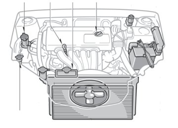
Engine maintenance
Driver seat
Store
Pull up
Turn
NOTE: Tighten until one click is heard. If the cap is not tightened enough, Check Engine “ ” indicator may illuminate. Hood release
Pull
Pull up latch and raise hood
Keyless entry (if equipped) Locking operation Push
Unlocking operation Push ONCE: Driver door
TWICE: All doors
Power steering fluid reservoir Engine oil level dipstick Engine coolant reservoir Engine oil filler cap Windshield and rear window washer fluid tank
Note: Regularly scheduled maintenance, including
oil changes, will help extend the life of your vehicle and maintain performance. Please refer to the “Owner’s Warranty Information Booklet,” “Scheduled Maintenance Guide” or “Owner’s Manual Supplement.”
NOTE: After unlocking, if a door is not opened within thirty (30) seconds, all doors will relock for safety Glass hatch opener Push and hold
Alarm operation Push
FEATURES/OPERATIONS
Auto lock functions (if equipped) Automatic door locks can be programmed to operate in 4 different modes.
-Doors lock when shifting from “Park.” -Doors unlock when shifting into “Park.” -Doors unlock when the ignition key is turned to the “ACC” or “LOCK” position and driver’s door is opened. -Deactivate, auto lock function cancelled. Refer to the Owner’s Manual for more details. Automatic Transmission (if equipped)
Park1
Reverse Neutral Drive Second gear First gearOverdrive switch
1 The ignition must be ON, and the brake pedal depressed to shift from “Park.”
Downshifting increases power going uphill, or provides engine braking downhill. For best fuel economy during normal driving conditions, always drive with the shift lever in the “D” position. Overdrive switch To turn “ON” or “OFF” Depress the overdrive switch to choose either three-speed (“OFF”) or four- speed (“ON”) operation. During normal driving conditions, always drive with overdrive “ON;” this allows the transmission to shift automatically into four-speed operation at higher speeds, improving fuel economy. If the indicator light on the instrument cluster is illuminated, overdrive is “OFF.”
Seats-Head restraints Front
Rear
Lock release button
Lock release button
Seat adjustments-Front
Position Height crank (driver side only) Seatback angle
Seat adjustments-Rear
(1) Unlock
(2) Lower
(3) Fold down
Clock
H-Hour set M-Minute set
FEATURES/OPERATIONS
Door locks-Power (if equipped)
Unlock
Lock
Lights & turn signals Headlights
Headlights
Parking lights
High beam
Low beam
High beam flasher
Turn signals
Right turn
Lane change
Lane change
Left turn
Front fog lights (if equipped)
Turn
Wiper & washer lever-Front/Rear Front operation
Adjust interval
Single wipe
Pull to wash and wipe
Rear operation
Interval wipe
Slow
Fast
Wash and wipe
Wipe
Interval wipe
Wash and wipe
Light control-Instrument panel
Full intensity position
Brightness control
Window-Glass hatch
Back door lock position
Front fog lights turn on only when the headlights are on low beam.
To open with key Turn the key FULLY clockwise. To open with opener switch* Push and hold the switch when the vehicle is stopped.
* If equipped
10
11
FEATURES/OPERATIONS
Windows-Power (if equipped) Driver side Passenger window lock switch
Up
Up
Down
Down
Window operation Automatic down operation (Driver side only) Push the switch completely down and release to fully open. To stop window mid-way, lightly pull the switch up. Window lock switch Deactivates all passenger windows. Driver’s window remains operable.
Moonroof (if equipped) Sliding operation
Tilting operation
Open
Close
Tilt
Close
Cup holders Front
Rear
12
Audio Type 1
Push to turn ON/OFFSeek station/ CD track select
Preset buttons - button functions in other modes indicated above number
Push to adjust tone and balance Station /CD track scan
Mode
Type 2 additional functions
Load CD(s)
Eject CD
View Radio and CD text
View genre with RDS system
Traffic information
> >
RADIO To preset stations Tune in the desired station and press a preset button (1-6) until you hear a beep. Push desired preset button (1-6) to select. To scan stations Push and hold to scan preset stations. Push again to hold selection. RDS (Radio Data System-FM only) (Type 2 only) -Push TYPE “ ” or “ ” to view current program genre. Push again within 6 seconds to select new genre. -Push “SEEK/TRACK” or “SCAN” to find same genre program. -Push “TEXT” to receive information transmitted from radio stations. CD PLAYER To scan tracks on a disc Push and hold “SCAN.” Push again to hold selection. CD Changer (Type 2 only) -To load one disc Push “LOAD” and insert one disc. -To load multiple discs Push and hold “LOAD” until you hear a beep. Insert one disc. Wait until the green indicator illuminates and shutter opens to insert next disc.
13
FEATURES/OPERATIONS
Air Conditioning (if equipped)/Heating
Cruise control (if equipped) Turning system ON/OFF
System ON/OFF
Functions
Cancel1
Resume2/Increase speed
Set/Decrease speed
1 The set speed may also be cancelled by depressing
the brake pedal or the clutch pedal.
2 The set speed may be resumed once vehicle speed
exceeds 25 mph. Refer to the Owner’s Manual for more details. Tilt steering wheel
Angle
Lock release lever
Hold wheel, push lever down, set angle, then return lever. Note: Do not attempt to adjust while the vehicle
is in motion. Parking brake Set
Release
(1) Pull slightly
Rear defogger Air flow vent In “ ” or “ ” mode, use fresh air (“ ” indicator “OFF”) to reduce window fogging. Fan speed Temperature Fresh or recirculate cabin air Air Conditioning ON/OFF
Power outlets Shifter area (12V)
Center console box (12V)
Designed for 12V car accessories. Key must be in the “ACC” or “ON” position to be used. Shifter area (115V, if equipped)
Main switch
Key must be in the “ON” position.
14
Pull
(2) Push
(3) Lower
15
SAFETY AND EMERGENCY FEATURES Seat belts
Take up slack
Too high
Keep as low on hips as possible
If belt is fully extended, then retracted even slightly, it cannot be re-extended beyond that point, unless fully retracted again. This feature is used to help hold child restraint systems securely.
To find more information about seat belts, and how to install a child restraint system, refer to the Owner’s Manual. Seat belts-Shoulder belt anchor
Squeeze lock release to lower or raise
Tire Pressure Warning System reset (if equipped)
If tire pressure becomes critically low on any of the tires (excluding compact spare), indicator illuminates. Pushing “SET” button should not turn off the light. Correctly adjusting tire inflation will turn off the light after a few minutes. After replacing tire or wheels, push and hold “SET” button until the indicator blinks 3 times.
16
2007
Corolla Matrix
This Pocket Reference Guide is a summary of basic vehicle operations. It contains brief descriptions of fundamental operations so you can locate and use the vehicle’s main equipment quickly and easily.
The Pocket Reference Guide is not intended as a substitute for the Owner’s Manual located in the vehicle’s glove box. We strongly encourage you to review the Owner’s Manual and supplementary manuals so you will have a better understanding of the vehicle’s capabilities and limitations.
Your dealership and the entire staff of Toyota Motor Sales, U.S.A., Inc. wish you many years of satisfied driving in your new Corolla Matrix.
! A word about safe vehicle operations This Pocket Reference Guide is not a full description of Corolla Matrix operations. Every Corolla Matrix owner should review the Owner’s Manual that accompanies this vehicle.
Pay special attention to the boxed information highlighted in yellow throughout the Owner’s Manual. Each box contains safe operating instructions to help you avoid injury or equipment malfunction.
All information in this Pocket Reference Guide is current at the time of printing. Toyota reserves the right to make changes at any time without notice.
Doors-Child safety locks
Rear door
Move the lever to “LOCK,” allowing the door to be opened only from the outside.
Spare tire & tools Tool location
Jack handle
Spare tire
Removing the spare tire
Wheel nut wrench
Jack
Loosen and remove the nut. Remove the luggage storage box. Loosen and remove the bolt.
Refer to the Owner’s Manual for tire changing and jack positioning procedures.
17
SECTION 1− 1
OPERATION OF INSTRUMENTS AND CONTROLS Overview of instruments and controls Instrument panel overview Instrument cluster overview Indicator symbols on the instrument panel
. . . . . . . . . . . . . . . . . . . . . . . . . . . . . . . . . . . . . . . . . . . . . . . . . . . . . . . . . . . . . . . . . . . . . . . . . . . . . . . . . . . . . . . . . . . . . . . .
Instrument panel overview (cid:1)View A
1. Side defroster outlets 2. Side vents 3. Instrument cluster 4. Center vents 5. Personal lights 6. Electric moon roof switches and
personal light
7. Power door lock switches 8. Power window switches 9. Glove box 10. Portable ashtray 11. Cup holders 12. Power outlet (12 VDC) 13. Parking brake lever 14. Auxiliary boxes 15. Automatic transmission selector lever
or manual transmission gear shift lever
16. Hood lock release lever 17. Window lock switch
(cid:1)View B
1. Power rear view mirror control switches 2. Instrument panel light control dial 3. Headlight, turn signal and front fog
light switches
4. Wiper and washer switches 5. Air conditioning controls 6. Rear window defogger switch 7. Emergency flasher switch 8. Clock 9. Front passenger’s seat belt reminder
light/front passenger occupant classification indicator light
10. Audio system 11. Auxiliary box or power outlet (115 VAC) 12. Power outlet (12 VDC) or cigarette
lighter
13. Ignition switch 14. Cruise control switch 15. Tilt steering lock release lever 16. “TRAC OFF” (traction control system
off) switch
17. Engine immobilizer system/Toyota vehicle intrusion protection system indicator light
18. Tire pressure warning system reset
switch
19. Glass hatch opener switch
Instrument cluster overview
1. Tachometer 2. Service reminder indicators and
indicator lights
3. Speedometer
4. Fuel gauge 5. Low fuel level warning light 6. Engine coolant temperature gauge
7. Trip meter reset knob 8. Odometer, two trip meters and outside
temperature display
Indicator symbols on the instrument panel
or
Brake system warning light* 1
or
Anti−lock brake system warning light* 1
Driver’s seat belt reminder light* 1
Open door warning light* 1
Front passenger’s seat belt reminder light* 1
SRS warning light* 1
Vehicle stability control system/traction control system warning light* 1
Charging system warning light* 1
Low tire pressure warning light* 1
Low engine oil pressure warning light* 1
Low windshield washer fluid level warning light* 1
or
Malfunction indicator lamp* 1
Engine oil replacement reminder light* 1
Front passenger occupant classification indicator light
Headlight indicator light
Tail light indicator light
Headlight high beam indicator light
Turn signal indicator lights
Overdrive−off indicator light
Slip indicator light/traction control system off indicator light
Cruise control indicator light* 2
* 1: For details, see “Service reminder indicators and warning
* 2:
buzzers” on page 105 in Section 1−6. If this light flashes, see “Cruise control” on page 130 in Section 1−7.
8
SECTION 1− 10
OPERATION OF INSTRUMENTS AND CONTROLS Other equipment Clock Cigarette lighter and portable ashtray Power outlets (12 VDC) Power outlet (115 VAC) Compass Glove box Auxiliary box Rear console box Cup holders Seatback tables Luggage storage boxes Tie−down hooks and tire tie−down belts Luggage deck rails Luggage cover Floor mat
. . . . . . . . . . . . . . . . . . . . . . . . . . . . . . . . . . . . . . . . . . . . . . . . . . . . . . . . . . . . . . . . . . . . . . . . . . . . . . . . . . . . . . . . . . . . . . . . . . . . . . . . . . . . . . . . . . . . . . . . . . . . . . . . . . . . . . . . . . . . . . . . . . . . . . . . . . . . . . . . . . . . . . . . . . . . . . . . . . . . . . . . . . . . . . . . . . . . . . . . . . . . . . . . . . . . . . . . . . . . . . . . . . . . . . . . . . . . . . . . . . . . . . . . . . . . . . . . . . . . . . . . . . . . . . . . . . . . . . . . . . . . . . . . . . . . . . . . . . . . . . . . . . . . . . . . . . . . . . . . . . . . . . . . . . . . . . . . . . . . . . . . . . . . . . . . . . . . . . . . . . . . . . . . . . . . . . . . . . . . . . . . . . . . . . . . . . . . . . . . . . . . . . . . . . . . . . . . . . . . . . . . . . . . . . . . . . . . . . . . . . . . . . . . . . . . . . . . . . . . . . . . . . . . . . . . . . . . . . . . . . . . . . . . . . . . . . . . . . . . . . . . . . . . . . . . . . . . . . . . . . . . . . . . . . . . . . . . . . . . . . . . . . . . . . . . . . . . . . . . . . . . . . . . . . . . . . . . . . . . . . . . . . . . . . . . . . . . . . . . . . . . . . . . . . . . . . . . . . . . . . . . . . . . . . . .
162
162
163
164
165
169
169
170
172
172
173
174
175
176
177161
Clock
Cigarette lighter and portable ashtray
To reset the hour: Push the “H” button. To reset the minutes: Push the “M” button. The key must be in the “ACC” or “ON” position. If the electrical power source has been disconnected from the clock, the time dis- play will automatically be set to 1:00. lights are When turned on, the brightness of the time indi- cator will be reduced.
instrument panel
the
CIGARETTE LIGHTER To use the cigarette lighter, press it in. After it finishes heating up, it automati- cally pops out ready for use. If the engine is not running, the key must be in the “ACC” position. Do not hold the cigarette lighter pressed in. Use a Toyota genuine cigarette lighter or equivalent for replacement.
PORTABLE ASHTRAY The ashtray can be removed and used outside the vehicle. To use the ashtray, open the lid. When finished with your cigarette, thor- oughly extinguish it in the ashtray to pre- vent other cigarette butts from catching fire. After using the ashtray, close the lid completely. To remove the ashtray, pull it out from the front cup holder.
162
Power outlets (12 VDC)
CAUTION
To reduce the chance of in case of an accident or sudden stop while driving, always completely close the ashtray after use.
injury
Instrument panel
Rear console box
The power outlets are designed power supply for car accessories. The key must be in the “ACC” or “ON” position for the power outlets to be used.
for
NOTICE
(cid:1) To prevent the fuse from being blown, do not use the electricity over the total vehicle capacity of 12
V/120W (instrument panel and rear console box outlets together).(cid:1) To prevent the battery from being discharged, do not use the power outlets longer than necessary when the engine is not running.
(cid:1) Close the power outlet lids when the power outlets are not in use. Inserting anything other than an ap- propriate plug that fits the outlet, or allowing any liquid to get into the outlet may cause electrical fail- ure or short circuits.
163
Power outlet (115 VAC)
This power outlet is designed for use as a power supply for electric ap- pliances in the vehicle. The key must be in the “ON” position for the power outlet to be used. The maximum capacity for this power out- let is 115 VAC/100W. If you attempt to use an appliance that requires more than 115 VAC or 100W, the protection circuit will activate and cut the power supply. The power supply will restart automatically when you use an appliance that operates within the 115 VAC/100W limits.
To use the power outlet, push the main switch on the instrument panel. An indicator light will illuminate to indicate that the power outlet is ready for use. Push the main switch once again to turn the power outlet off. When the power out- let is not in use, make sure that the main switch is turned off.
NOTICE
(cid:1) To prevent the battery from being discharged, do not use the power outlet longer than necessary when the engine is not running.
164
(cid:1) Close the power outlet lid when the power outlet is not in use. Inserting anything other than an appropriate plug that fits the outlet may cause electrical failure or short circuits.
The power outlet is not designed for the following electric appliances even though their power consumption is un- der 115 VAC/100W. These appliances may not operate properly. (cid:1) Appliances with high initial peak watt- age: cathode−ray tube type televisions, compressor−driven refrigerators, electric pumps, electric tools, etc.
(cid:1) Measuring devices which process pre- cise data: medical equipment, measur- ing instruments, etc.
(cid:1) Other appliances requiring an extremely stable power supply: microcomputer− controlled electric blankets, touch sen- sor lamps, etc.
Certain electrical appliances may cause radio noise.
Compass
indicates
the vehicle
the direction The compass that the above case, it shows that the vehicle is heading north.
is heading.
In
Displays
NE SE SW NW
Directions
North
Northeast
East
Southeast
South
Southwest
West
Northwest
The compass may not show the correct direction in the following conditions: (cid:1) The vehicle is stopped immediately af-
ter turning.
(cid:1) The compass does not adjust while the
vehicle is stopped.
(cid:1) The ignition switch is turned off imme-
diately after turning.
(cid:1) The vehicle is on an inclined surface.
The direction is indicated on the inside rear view mirror. If the ignition switch was turned off with the system on, the system will automati- cally turn back on when the ignition switch is turned on. To turn on the compass, push and hold the “ ” switch until the display turns on. To turn off the compass, push and hold ” switch until the display turns the “ off.
(cid:1) The vehicle is in a place where the earth’s magnetic field is subject to in- terference by artificial magnetic fields (underground parking, under a steel tower, between buildings, roof parking, near a crossing, near a large vehicle, etc.).
(cid:1) The vehicle is magnetized. (There is a magnet or a metal object on or near the inside rear view mirror.)
the deviation
(cid:1) The battery has been disconnected. If your vehicle is out of the set zone, refer to “CALIBRATING THE COMPASS” below to set the zone number. If the compass works to calibrate the direction automati- cally while the vehicle is in motion. For additional precision or calibrating, see COMPASS” below.
for complete THE
“CALIBRATING
is small,
165
The compass sensor is in the inside rear view mirror.
NOTICE
Do not put magnets or a metal object on or near the inside rear view mirror of the vehicle. Doing this may cause malfunction of the compass sensor.
166
the
from
CALIBRATING THE COMPASS (deviation calibration) the compass The direction display on true direction deter- deviates mined by the earth’s magnetic field. The angle of deviation varies according to the geographic position of the vehicle. To adjust this deviation, stop the vehicle, then push and hold the both personal light switches until the zone number appears on the display. Then push the right side or left side personal light switch, referring to the following map to select the number of the zone where the vehicle is.
Samoa: 5
Guam:
Saipan: 8
After calibration, leaving the system for several seconds returns it to the compass mode.
CAUTION
Do not adjust the display while the vehicle is moving. Be sure to adjust the display only when the vehicle is stopped.
Zone number
167
Perform circling calibration just after you have purchased your Toyota. And then always perform circling calibration after the battery has been removed, re- placed or disconnected. (cid:1) Do not perform circling calibration of the compass the earth’s magnetic field is subject to in- terference by artificial magnetic fields (underground parking, under a steel tower, between buildings, roof parking, near a crossing, near a large vehicle, etc.).
in a place where
(cid:1) During calibration, do not operate elec- tric systems (moon roof, power win- dows, etc.) as they may interfere with the calibration.
the direction display on
CALIBRATING THE COMPASS (circling calibration) Sometimes the compass may not change after a turn. To rectify this, stop the vehicle and push and hold the both personal light switches until “C” appears on the display. If “C” appears on the display because of a drastic change in the magnetic field, perform circling calibration.
in a circle, drive around
Drive the vehicle in a circle at 8 km/h (5
mph) or less. If there is not enough space to drive the block. After driving 1 to 3 circles in the above method, calibration is completed when the direction is shown on the display. If calibration cannot be performed because