- 2009 Toyota Highlander Owners Manuals
- Toyota Highlander Owners Manuals
- 2004 Toyota Highlander Owners Manuals
- Toyota Highlander Owners Manuals
- 2014 Toyota Highlander Owners Manuals
- Toyota Highlander Owners Manuals
- 2010 Toyota Highlander Owners Manuals
- Toyota Highlander Owners Manuals
- 2005 Toyota Highlander Owners Manuals
- Toyota Highlander Owners Manuals
- 2015 Toyota Highlander Owners Manuals
- Toyota Highlander Owners Manuals
- 2003 Toyota Highlander Owners Manuals
- Toyota Highlander Owners Manuals
- 2001 Toyota Highlander Owners Manuals
- Toyota Highlander Owners Manuals
- 2006 Toyota Highlander Owners Manuals
- Toyota Highlander Owners Manuals
- 2011 Toyota Highlander Owners Manuals
- Toyota Highlander Owners Manuals
- 2002 Toyota Highlander Owners Manuals
- Toyota Highlander Owners Manuals
- 2007 Toyota Highlander Owners Manuals
- Toyota Highlander Owners Manuals
- Download PDF Manual
-
power back door) →P. 59
■ Front bulb locations
Parking, front side marker and front turn signal lights Fog lights (if equipped)
Headlight low beams
Headlight high beams and daytime running lights (if equipped)
487
Rear turn signal lights
Stop/tail and rear side marker lights
Back-up lights
Turn the bulb base counterclock- wise.
Low beam (outside) High beam (inside)
4-3. Do-it-yourself maintenance
■ Rear bulb locations
License plate lights
Replacing light bulbs
■ Headlights STEP 1
488
4-3. Do-it-yourself maintenance
STEP 2
Unplug depressing the lock release.
the connector while
Low beam High beam
■ Fog lights (if equipped)
STEP 1
Unplug depressing the lock release.
the connector while
489
4-3. Do-it-yourself maintenance
STEP 2
Turn the bulb counterclockwise.
■ Parking, front side marker and front turn signal lights STEP 1
Turn the bulb base counterclock- wise.
STEP 2
Remove the light bulb.
490
4-3. Do-it-yourself maintenance
■ Back-up lights, stop/tail and rear side marker, and rear turn
signal lights Left side
STEP 1
Right side
STEP 1
STEP 2
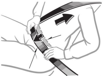
Open the back door and remove the cover.
To protect the cover, place a rag between the flathead screwdriver and cover as shown in the illus- trations.
Open the back door and remove the cover.
To protect the cover, place a rag between the flathead screwdriver and cover as shown in the illus- trations.
Turn the bulb base counterclock- wise.
Rear turn signal light Stop/tail and rear side marker light Back-up light
491
4-3. Do-it-yourself maintenance
STEP 3
Remove the light bulb. Rear turn signal light Stop/tail and rear side marker light Back-up light
■ License plate lights STEP 1
Remove the screw and remove the unit.
STEP 2
Turn the bulb base counterclock- wise.
STEP 3
Remove the light bulb.
492
4-3. Do-it-yourself maintenance
■ High mounted stoplight and outer foot lights
If the high mounted stoplight or outer foot light has burnt out, have it replaced by your Toyota dealer.
■Condensation build-up on the inside of the lens
Contact your Toyota dealer for more information in the following situations. Temporary condensation build-up on the inside of the headlight lens does not indicate a malfunction. ●Large drops of water are built up on the inside of the lens. ●Water has built up inside the headlight.
■LED high mounted stoplight
The high mounted stoplight consists of a number of LEDs. If any of the LEDs burn out, take your vehicle to your Toyota dealer to have the light replaced.
CAUTION
■Replacing light bulbs
●Turn off the headlights. Do not attempt to replace the bulb immediately
after turning off the headlights. The bulbs become very hot and may cause burns.
●Do not touch the glass portion of the light bulb with bare hands. Hold the
bulb by the plastic or metal portion. If the bulb is scratched or dropped it may blow out or crack.
●Fully install light bulbs and any parts used to secure them. Failing to do so may result in heat damage, fire, or water entering the headlight unit. This may damage the headlights or cause condensation to build up on the lens.
■To prevent damage or fire
Make sure bulbs are fully seated and locked.
493
4-3. Do-it-yourself maintenance
494
5-1. Essential information Emergency flashers
Use the emergency flashers if the vehicle malfunctions or is involved in an accident.
Vehicles without navigation system
Press the switch to flash all the turn signal lights. To turn them off, press the switch once again.
Vehicles with navigation system
Press the switch to flash all the turn signal lights. To turn them off, press the switch once again.
NOTICE
■To prevent battery discharge
Do not leave the emergency flashers on longer than necessary when the engine is not running.
496
5-1. Essential information If your vehicle needs to be towed
If towing is necessary, we recommend having your vehicle towed by your Toyota dealer or a commercial towing service, using a lift-type truck or a flat bed truck. Use a safety chain system for all towing, and abide by all state/pro- vincial and local laws. 2WD models: If towing from the front, the vehicle's rear wheels and axles must be in good condition. (→P. 501) If they are damaged, use a towing dolly or flat bed truck.
Before towing
The following may indicate a problem with your transmission. Contact your Toyota dealer before towing. ● The engine is running, but the vehicle will not move. ● The vehicle makes an abnormal sound.
497
5-1. Essential information
Emergency towing
If a tow truck is not available, in an emergency your vehicle may be temporarily towed using a cable or chain secured to the emergency towing eyelet(s). This should only be attempted on hard surfaced roads for short distances at low speeds. A driver must be in the vehicle to steer and operate the brakes. The vehicle’s wheels, drive train, axles, steering and brakes must be in good condition.
Towing eyelets
■Emergency towing procedure
STEP 1
STEP 2
STEP 3
Release the parking brake. Shift the shift lever to N. Vehicles without smart key system: Turn the engine switch to “ACC” (engine off) or “ON” (engine run- ning) position. Vehicles with smart key system: Turn the “ENGINE START STOP” switch to ACCESSORY (engine off) or IGNITION ON (engine running) mode.
498
5-1. Essential information
CAUTION
■Caution while towing
●Use extreme caution when towing the vehicle.
Avoid sudden starts or erratic driving maneuvers which place excessive stress on the emergency towing eyelets and the cables or chains. Always use caution for the surroundings and other vehicles while towing.
●If the engine is not running, the power assist for the brakes and steering
will not function, making steering and braking more difficult.
NOTICE
■To prevent causing serious damage to the transmission
Never tow this vehicle from the rear with the front wheels on the ground. This may cause serious damage to the transmission.
Installing a towing eyelet
STEP 1
STEP 2
Remove the eyelet cover using a flathead screwdriver.
To protect the bodywork, place a rag between the screwdriver and the vehicle body, as shown in the illustration.
Insert the towing eyelet into the hole and tighten partially by hand.
499
5-1. Essential information
STEP 3
Tighten down the towing eyelet securely using a wheel nut wrench.
■Location of the emergency towing eyelet
→P. 520
CAUTION
■Installing towing eyelet to the vehicle
Make sure that towing eyelet is installed securely. If not securely installed, towing eyelet may come loose during towing. This may lead to accidents that cause serious injury or even death.
500
5-1. Essential information
Towing with a sling-type truck
NOTICE
■To prevent body damage
Do not tow with a sling-type truck, either from the front or rear.
Towing with a wheel lift-type truck
From front (2WD models)
Release the parking brake.
501
5-1. Essential information
From front (4WD models)
Use a towing dolly under the rear wheels.
NOTICE
■To prevent damaging the vehicle
When raising the vehicle, ensure adequate ground clearance for towing at the opposite end of the raised vehicle. Without adequate clearance, the vehicle could be damaged while being towed.
■To prevent causing serious damage to the transmission (4WD models)
Never tow this vehicle from the front with the rear wheels on the ground.
Use a towing dolly under the front wheels.
From rear
NOTICE
■To prevent causing serious damage to the transmission
Never tow this vehicle from the rear with the front wheels on the ground.
502
Using a flat bed truck
5-1. Essential information
If your Toyota is transported by a flatbed truck, it should be tied down at the locations shown in the illustration.
If you use chains or cables to tie down your vehicle, the angles shaded in black must be 45°. Do not overly tighten the tie downs or the vehicle may be damaged.
503
5-1. Essential information If you think something is wrong
If you notice any of the following symptoms, your vehicle probably needs adjustment or repair. Contact your Toyota dealer as soon as possible. ■ Visible symptoms
● Fluid leaks under the vehicle
(Water dripping from the air conditioning after use is normal.)
● Flat-looking tires or uneven tire wear ● Engine coolant temperature gauge needle continually points
higher than normal ■ Audible symptoms
● Changes in exhaust sound ● Excessive tire squeal when cornering ● Strange noises related to the suspension system ● Pinging or other noises related to the engine
■ Operational symptoms
● Engine missing, stumbling or running rough ● Appreciable loss of power ● Vehicle pulls heavily to one side when braking ● Vehicle pulls heavily to one side when driving on a level road ● Loss of brake effectiveness, spongy feeling, pedal almost
touches the floor
504
5-1. Essential information Fuel pump shut off system
To minimize the risk of fuel leakage when the engine stalls or an air- bag inflates upon collision, the fuel pump shut off system stops sup- plying fuel to the engine.
Follow the procedure below to restart the engine after the system is activated.
Vehicles without smart key system
STEP 1
STEP 2
Turn the engine switch to the “ACC” or “LOCK” position. Restart the engine.
Vehicles with smart key system
STEP 1
STEP 2
Turn the “ENGINE START STOP” switch OFF. Restart the engine.
NOTICE
■Before starting the engine
Inspect the ground under the vehicle. If you find that fuel has leaked onto the ground, the fuel system has been damaged and is in need of repair. Do not restart the engine.
505
5-1. Essential information Event data recorder
Your vehicle has computers that monitor and control certain aspects of your vehicle. These computers assist in driving and maintaining optimal vehicle performance. Besides storing data useful for troubleshooting, there is an event data recorder (EDR) that records data in a crash or a near car crash event.
In a crash or a near car crash event
The SRS airbag sensor assembly contains the EDR. In a crash or a near car crash event, this device may record some or all of the follow- ing information: ● Engine speed ● Whether the brake pedal was depressed or not ● Vehicle speed ● To what extent the accelerator pedal was depressed ● Position of the transmission shift lever ● Whether the driver and front passenger wore seat belts or not ● Driver's seat position ● SRS airbag deployment data ● SRS airbag system diagnostic data ● Front passenger’s occupant classification The information above is intended to be used for the purpose of improving vehicle safety performance. Unlike general data recorders, the EDR does not record sound data such as conversation between passengers.
506
5-1. Essential information
Disclosure of the data
Toyota will not disclose the data recorded in an EDR to a third party except when: ● An agreement from the vehicle's owner (or the leasing company for
a leased vehicle) is obtained
● Officially requested by the police or other authorities ● Used as a defense for Toyota in a law suit ● Ordered by a court law However, if necessary Toyota will: ● Use the data for research on Toyota vehicle safety performance ● Disclose the data to a third party for research purposes without dis- closing details of the vehicle owner, and only when it is deemed necessary
● Disclose summarized data cleared of vehicle identification informa-
tion to a non-Toyota organization for research purposes
507
5-2. Steps to take in an emergency If a warning light turns on or a warning buzzer sounds...
Calmly perform the following actions if any of the warning lights turn on or flash. If a light turns on or flashes, but then turns off, this does not necessarily indicate a malfunction in the system.
Stop the vehicle immediately. Continuing to drive the vehicle may be dangerous.
The following warning indicates a possible problem in the brake sys- tem. Immediately stop the vehicle in a safe place and contact your Toyota dealer.
Warning light
Warning light/Details
Brake system warning light (warning buzzer)* • Low brake fluid • Malfunction in the brake system This light also comes on when the parking brake is not released. If the light turns off after the parking brake is fully released, the system is operating normally.
(U.S.A.)
(Canada)
*: Parking brake engaged warning buzzer:
A buzzer sounds to indicate that the parking brake is still engaged (with the vehicle having reached a speed of 3 mph [5 km/h]).
508
5-2. Steps to take in an emergency
Stop the vehicle immediately.
The following warnings indicate the possibility of damage to the vehi- cle that may lead to an accident. Immediately stop the vehicle in a safe place and contact your Toyota dealer.
Warning light
Warning light/Details
Charging system warning light Indicates a malfunction in the vehicle’s charging system.
Low engine oil pressure warning light (vehicles without multi-information display) Indicates that the engine oil pressure is too low.
Have the vehicle inspected immediately.
Failing to investigate the cause of the following warnings may lead to the system operating abnormally and possibly cause an accident. Have the vehicle inspected by your Toyota dealer immediately.
Warning light
Warning light/Details
(U.S.A.)
(Canada)
Malfunction indicator lamp Indicates a malfunction in: • The electronic engine control system; • The electronic throttle control system; or • The electronic automatic transmission control system.
SRS warning light Indicates a malfunction in: • The SRS airbag system; • The front passenger occupant classification system; or • The seat belt pretensioner system.
509
5-2. Steps to take in an emergency
Warning light
Warning light/Details
ABS warning light Indicates a malfunction in: • The ABS; or • The brake assist system.
(U.S.A.)
(Canada)
Electric power steering warning light Indicates a malfunction in the EPS (Electric Power Steer- ing) system. Slip indicator light Indicates a malfunction in: • The Enhanced VSC system; • The TRAC system; • The hill-start assist control system; or • The downhill assist control system (4WD models).
Cruise control indicator light (if equipped) Indicates a malfunction in the cruise control system.
(Flashes)
■If the malfunction indicator lamp comes on while driving
First check the following: ●Is the fuel tank low or empty?
If it is, fill the fuel tank immediately.
●Is the fuel tank cap loose?
If it is, tighten it securely.
The light will go off after taking several driving trips. If the light does not go off even after several trips, contact your Toyota dealer as soon as possible.
510
5-2. Steps to take in an emergency
Follow the correction procedures.
After taking the specified steps to correct the suspected problem, check that the warning light turns off.
Warning light
Warning light/Details
Correction procedure
Open door warning light (warning buzzer)*1
Indicates that a door is not fully closed. Low fuel level warning light Indicates that remaining fuel is about 2.2 gal. (8.3 L, 1.8 Imp. gal.) or less Driver’s seat belt reminder light (warning buzzer)*2
Warns the driver to fasten his/her seat belt.Front passenger’s seat belt reminder light (warning buzzer)*2
Warns the front passen- ger to fasten his or her seat belt.Automatic transmission fluid temperature warning light (vehicles without multi-information display) Indicates that the auto- matic transmission fluid temperature is too high.
Check that all doors are closed.
Refuel the vehicle.
Fasten the seat belt.
Fasten the seat belt.
Stop the vehicle in a safe place and shift the shift lever to P. If the light does not go off, contact your Toyota dealer.
511
*3
*4
(On the center
panel)
5-2. Steps to take in an emergency
Warning light
Warning light/Details
Correction procedure
Low washer fluid warning light (vehicles without multi-information display) Low level of washer fluid Engine oil replacement reminder light (vehicles without multi-information display) Illuminates for about 3 sec- onds and then flashes for about 12 seconds: Indicates that the engine oil is sched- uled to be changed. Comes on and remains: Indicates that the engine oil should be changed. Tire pressure warning light
Fill the tank.
Check and change the engine oil if necessary.
Check and change the engine oil.
When the light comes on: Low tire inflation pressure
Adjust the tire inflation pressure.
When the light comes on after blinking for 1 minute: Malfunction in the tire pressure warning system Master warning light (vehicles with multi-infor- mation display) A buzzer sounds and the warning light comes on and flashes to indicate that the master warning system has detected a malfunc- tion.
Have the system checked by your Toyota dealer.
→P. 519
(U.S.A.)
512
5-2. Steps to take in an emergency
*1: Open door warning buzzer:
The open door warning buzzer sounds to alert one or more of the doors is not fully closed (with the vehicle having reached a speed of 3 mph [5 km/h]).
*2: Driver's and front passenger’s seat belt reminders:
The driver’s and front passenger’s seat belt reminders sound to alert the driver and front passenger that his or her seat belt is not fastened. These buzzers sound for 10 seconds after the vehicle has reached a speed of at least 12 mph (20 km/h). Then, if the seat belt is still unfastened, the buzzer will sound in a different tone for 20 more seconds.
*3: Vehicles without navigation system *4: Vehicles with navigation system
■Key reminder buzzer (vehicles without smart key system)
The buzzer indicates that the key has not been removed with the engine off and the driver’s door opened.
■Open moon roof reminder buzzer (vehicles with multi-information dis-
play) The buzzer indicates that the moon roof is not fully closed with the engine off and the driver’s door opened.
■Front passenger detection sensor and passenger seat belt reminder
●If luggage is placed on the front passenger seat, the front passenger detection sensor may cause the warning light to flash, even if a passen- ger is not sitting in the seat.
●If a cushion is placed on the seat, the sensor may not detect a passen-
ger, and the warning light may not operate properly.
■Engine oil replacement reminder light (U.S.A. ⎯ vehicles without multi-
information display) The engine oil replacement reminder light will come on and flash at approxi- mately 4500 miles (7200 km) after an oil change. When the distance driven after an oil change exceeds approximately 5000 miles (8000 km), the light will come on and remain on.
■Changing the engine oil (U.S.A. only)
Make sure to reset the oil change system. (→P. 445)
513
5-2. Steps to take in an emergency
■When the tire pressure warning light comes on
Check the tire inflation pressure and adjust to the appropriate level. Pushing the tire pressure warning reset switch does not turn off the tire pressure warning light.
■The tire pressure warning light may turn on due to natural causes
The tire pressure warning light may turn on due to natural causes such as natural air leaks or tire inflation pressure changes caused by temper- ature. In this case, adjusting the tire inflation pressure will turn off the warning light (after a few minutes).
■When a tire is replaced with a spare tire
Without compact spare tire
The spare tire is also equipped with the tire pressure warning valve and transmitter. The tire pressure warning light will turn on if the tire inflation pressure of the spare tire is low. If a tire goes flat, even though the flat tire is replaced with the spare tire, the tire pressure warning light does not turn off. Replace the spare tire with the repaired tire and adjust the proper tire inflation pressure. The tire pressure warning light will turn off after a few minutes.
With compact spare tire
The compact spare tire is not equipped with the tire pressure warning valve and transmitter. If a tire goes flat, the tire pressure warning light will not turn off even though the flat tire is replaced with the spare tire. Replace the spare tire with the repaired tire and adjust the proper tire inflation pressure. The tire pressure warning light will turn off after a few minutes.
514
5-2. Steps to take in an emergency
■If the tire pressure warning system is inoperative
The tire pressure warning system will be disabled in the following condi- tions: (When the condition becomes normal, the system will work properly.) ●If tires not equipped with tire pressure warning valves and transmit-
ters are used.
●If the ID code on the tire pressure warning valves and transmitters is
not registered in the tire pressure warning computer.
●If the tire inflation pressure is 73 psi (500 kPa, 5.1 kgf/cm2 or bar) or
higher.
The tire pressure warning system may be disabled in the following condi- tions: (When the condition becomes normal, the system will work properly.) ●If electronic devices or facilities using similar radio wave frequencies
are nearby.
●If a radio set at similar frequencies is in use in the vehicle. ●If a window tint that affects the radio wave signals is installed. ●If there is a lot of snow or ice on the vehicle, in particular around the
wheels or wheel housings.
●If non-genuine Toyota wheels are used. (Even if you use Toyota wheels, the tire pressure warning system may not work properly with some types of tires.)
●If tire chains are used.
Vehicles without compact spare tire
●If the spare tire is in a location subject to poor radio wave signal
reception.
●If a large metallic object which can interfere with signal reception is
put in the luggage room.
515
5-2. Steps to take in an emergency
■If the tire pressure warning light comes on after blinking for 1
minute frequently
Vehicles without smart key system
If the tire pressure warning light comes on after blinking for 1 minute fre- quently when the engine switch is turned to the “ON” position, have it checked by your Toyota dealer.
Vehicles with smart key system
If the tire pressure warning light comes on after blinking for 1 minute fre- quently when the “ENGINE START STOP” switch is turned to IGNITION ON mode, have it checked by your Toyota dealer.
516
5-2. Steps to take in an emergency
CAUTION
■If the tire pressure warning light comes on
Be sure to observe the following precautions. Failure to do so could cause loss of vehicle control and result in death or serious injury. ●Stop your vehicle in a safe place as soon as possible. Adjust the tire
inflation pressure immediately.
●If the tire pressure warning light comes on even after tire inflation pres- sure adjustment, it is probable that you have a flat tire. Check the tires. If the tire is flat, change to the spare tire and have the flat tire repaired by the nearest Toyota dealer.
●Avoid abrupt maneuvering and braking. If the vehicle tires deteriorate,
you could lose control of the steering wheel or the brakes.
■If a blowout or sudden air leakage should occur
The tire pressure warning system may not activate immediately.
■Maintenance of the tires
Each tire, including the spare (if provided), should be checked monthly when cold and inflated to the inflation pressure recommended by the vehicle manufacturer on the vehicle placard or tire inflation pressure label (tire and load information label). (If your vehicle has tires of a differ- ent size than the size indicated on the vehicle placard or tire inflation pressure label [tire and load information label], you should determine the proper tire inflation pressure for those tires.) As an added safety feature, your vehicle has been equipped with a tire pressure monitoring system (TPMS-tire pressure warning system) that illuminates a low tire pressure telltale (tire pressure warning light) when one or more of your tires is significantly under-inflated. Accordingly, when the low tire pressure telltale (tire pressure warning light) illumi- nates, you should stop and check your tires as soon as possible, and inflate them to the proper pressure. Driving on a significantly under- inflated tire causes the tire to overheat and can lead to tire failure. Under-inflation also reduces fuel efficiency and tire tread life, and may affect the vehicle's handling and stopping ability.
517
5-2. Steps to take in an emergency
CAUTION
Please note that the TPMS (tire pressure warning system) is not a sub- stitute for proper tire maintenance, and it is the driver's responsibility to maintain correct tire pressure, even if under-inflation has not reached the level to trigger illumination of the TPMS low tire pressure telltale (tire pressure warning light). Your vehicle has also been equipped with a TPMS (tire pressure warning system) malfunction indicator to indicate when the system is not operat- ing properly. The TPMS (tire pressure warning system) malfunction indi- cator is combined with the low tire pressure telltale (tire pressure warning light). When the system detects a malfunction, the telltale will flash for approximately one minute and then remain continuously illumi- nated. This sequence will continue upon subsequent vehicle start-ups as long as the malfunction exists. When the malfunction indicator is illumi- nated, the system may not be able to detect or signal low tire pressure as intended. TPMS (tire pressure warning system) malfunctions may occur for a vari- ety of reasons, including the installation of replacement or alternate tires or wheels on the vehicle that prevent the TPMS (tire pressure warning system) from functioning properly. Always check the TPMS (tire pres- sure warning system) malfunction telltale after replacing one or more tires or wheels on your vehicle to ensure that the replacement or alter- nate tires and wheels allow the TPMS (tire pressure warning system) to continue to function properly.
NOTICE
■Precaution when installing a different tire
When a tire of a different specification or maker is installed, the tire pres- sure warning system may not operate properly.
518
5-2. Steps to take in an emergency If a warning message is displayed (vehicles with multi-information display)
The multi-information display shows warnings of system malfunc- tions or incorrectly performed operations. When a message is shown, perform corrections as indicated in the message.
Master warning light The master warning light also comes on or flashes in order to indicate that a message is currently being displayed on the multi-information display. Multi-information display Warning message Correction procedure
■ Warning buzzer
A buzzer may sound when a warning message is shown on the multi-information display.
■ If the warning message is shown again after its correction
procedure has been performed Contact your Toyota dealer as soon as possible.
519
5-2. Steps to take in an emergency If you have a flat tire
Remove the flat tire and replace it with the spare provided. ■ Before jacking up the vehicle
● Stop the vehicle on a hard, flat surface. ● Set the parking brake. ● Shift the shift lever to P. ● Stop the engine. ● Turn on the emergency flashers.
■ Location of the spare tire, jack and tools
Adapter socket
Jack handle
Towing eyelet
Wrench
Jack handle
Jack
Spare tire
520
5-2. Steps to take in an emergency
Taking out the jack
STEP 1
Remove board.
the right side deck
STEP 2
STEP 3
Unhook the tightening strap and remove the pad.
After storing the jack, make sure it is securely held by the tightening strap.
Loosen Tighten
521
5-2. Steps to take in an emergency
Taking out the spare tire
STEP 1
Open the center deck board and remove the cover.
STEP 2
Remove the cover.
If it is difficult to remove the cover, you can use the key.
STEP 3
Attach the adapter socket (for removing a spare tire) to the spare tire clamp bolt.
522
5-2. Steps to take in an emergency
STEP 4
Assembling the jack handle.
the
Remove jack handle and assemble it by following these steps. Loosen the screw. Assemble the jack handle and tighten the screw. Check that the screw is firmly tightened.
STEP 5
Connect the jack handle and the adapter socket. Turn the jack handle.
The tire will be lowered com- pletely to the ground.
523
5-2. Steps to take in an emergency
STEP 6
Pull out the spare tire and stand it against the bumper.
STEP 7
Remove the holding bracket.
524
5-2. Steps to take in an emergency
Replacing a flat tire
STEP 1
STEP 1Chock the tires.
Flat tire
Front
Rear
Left- hand side
Right- hand side
Left- hand side
Right- hand side
Wheel chock positions Behind the rear right- hand side tire Behind the rear left- hand side tire In front of the front right-hand side tire In front of the front left-hand side tire
STEP 2
Slightly loosen the wheel nuts (one turn).
525
Turn the tire jack portion “A” by hand until the notch of the jack is in contact with the jack point.
Raise the vehicle until the tire is slightly raised off the ground.
Remove all the wheel nuts and the tire.
When resting the tire on the ground, place the tire so that the wheel design faces up to avoid scratching the wheel surface.
5-2. Steps to take in an emergency
STEP 3
STEP 4
STEP 5
526
Installing the tire
STEP 1
5-2. Steps to take in an emergency
Remove any dirt or foreign mat- ter from the wheel contact sur- face.
If foreign matter is on the wheel contact surface, the wheel nuts may loosen while the vehicle is in motion, and the tire may come off the vehicle.
STEP 2
Install the tire and loosely tighten each wheel nut by hand by approximately the same amount.
Vehicles without compact spare tire
Disc wheel
Turn the nut washers until they come into contact with the disc wheel.
Washer
Vehicles with compact spare tire
Tapered portion
Tighten the nuts until the tapered portion comes into loose contact with the disc wheel seat.
Disc wheel seat
527
5-2. Steps to take in an emergency
STEP 3
Lower the vehicle.
STEP 4
Firmly tighten each nut two or three times in the order shown in the illustration.
Tightening torque: 76 ft•lbf (103 N•m, 10.5 kgf•m)
Stowing the flat tire, jack and all tools
STEP 1
Remove the center wheel ornament by pushing from the reverse side.
STEP 2
Put the flat tire on the ground with the outer side facing up and install the holding bracket.
Be careful not to lose the wheel ornament.
STEP 3
STEP 4
Turn the spare tire clamp bolt clockwise with a jack handle and adapter socket until you hear a click. Stow the jack and all tools.
528
5-2. Steps to take in an emergency
■The compact spare tire
●The compact spare tire is identified by the label “TEMPORARY USE
ONLY” on the tire sidewall. Use the compact spare tire temporarily only in an emergency.
●Make sure to check the tire inflation pressure of the compact spare
tire. (→P. 563)
■When using the compact spare tire
As the compact spare tire is not equipped with the tire pressure warning valve and transmitter, low inflation pressure of the spare tire will not be warned. Also, if you replace the compact spare tire after the tire pressure warning light comes on, the light remains on.
■If you have a flat front tire on a road covered with snow or ice (vehi-
cles with compact spare tire) Install the spare tire on the rear of the vehicle. Perform the following steps and fit tire chains to the front tires. STEP 1
Replace a rear tire with the compact spare tire. Replace the flat front tire with the tire removed from the rear of the vehicle. Fit tire chains to the front tires.
STEP 2
STEP 3
■After completing the tire change
The tire pressure warning system must be reset. (→P. 457)
529
5-2. Steps to take in an emergency
CAUTION
■Using the tire jack
Improper use of the tire jack may lead to death or serious injuries due to the vehicle suddenly falling off the jack. ●Do not use the tire jack for any purpose other than replacing tires or
installing and removing tire chains.
●Only use the tire jack that comes with this vehicle for replacing a flat
tire. Do not use it on other vehicles, and do not use other tire jacks for replacing tires on this vehicle.
●Always check that the tire jack is securely set to the jack point. ●Do not put any part of your body under the vehicle supported by a jack. ●Do not start or run the engine while your vehicle is supported by the
jack.
●Do not raise the vehicle while someone is in it. ●When raising the vehicle, do not put an object on or under the jack. ●Do not raise the vehicle to a height greater than that required to
replace the tire.
●Use a jack stand if it is necessary to get under the vehicle. Take particular care when lowering the vehicle to ensure that no one working on or near the vehicle will be injured.
530
5-2. Steps to take in an emergency
CAUTION
■Replacing a flat tire
Observe the following precautions to reduce the risk of death or serious injury. ●Never use oil or grease on the wheel bolts or wheel nuts.
Oil and grease may cause the wheel nuts to be excessively tightened, leading to bolt or disc wheel damage. In addition, the oil or grease can cause the wheel nuts to loosen and the wheel may fall off, causing a serious accident. Remove any oil or grease from the wheel bolts or wheel nuts.
●Have the wheel nuts tightened with a torque wrench to 76 ft•lbf (103
N•m, 10.5 kgf•m) as soon as possible after changing wheels. Failure to follow these precautions could cause the nuts to loosen and the wheel may fall off, which could lead to an accident causing death or serious injury.
■When using the compact spare tire
●Remember that your compact spare tire is specifically designed for use with your vehicle. Do not use your compact spare tire on another vehicle.
●Do not use two compact spare tires simultaneously. ●Replace the compact spare tire with a standard tire as soon as possi-
ble.
●Avoid sudden acceleration, deceleration and braking, as well as sharp
cornering.
■Speed limit when using the compact spare tire
Do not drive at speeds in excess of 50 mph (80 km/h) when a compact spare tire is installed on the vehicle. The compact spare tire is not designed for driving at high speeds. Failing to observe this precaution may lead to an accident causing death or seri- ous injury.
531
5-2. Steps to take in an emergency
CAUTION
■When the compact spare tire is attached
The vehicle speed may not be correctly detected, and the following sys- tems may not operate correctly: ●ABS & Brake assist ●Enhanced VSC ●TRAC ●Cruise control system (if equipped) ●Navigation system (if equipped) Also, not only can be following system not be utilized fully, it may actually negatively effect the drive-train components: (4WD models) ●4WD system
532
5-2. Steps to take in an emergency
NOTICE
■Do not drive the vehicle with a flat tire.
Do not continue driving with a flat tire. Driving even a short distance with a flat tire can damage the tire and the wheel beyond repair.
■Be careful when driving over bumps with the compact spare tire
installed on the vehicle. The vehicle becomes lower when driving with the compact spare tire compared to when driving with standard tires. Be careful when driving over uneven road surfaces.
■Driving with tire chains and the compact spare tire
Do not fit tire chains to the compact spare tire. Tire chains may damage the vehicle body and adversely affect driving performance.
■When replacing the tires
When removing or fitting the wheels, tires or the tire pressure warning valve and transmitter, contact your Toyota dealer as the tire pressure warning valve and transmitter may be damaged if not handled correctly. ■To avoid damaging the tire pressure warning valves and transmit-
ters Do not use liquid sealants on flat tires.
■When stowing the flat tire
●Ensure that there is no object caught between the tire and the vehicle
underbody.
●Tighten the spare tire clamp bolt to hold the spare wheel carrier by the
hook securely.
533
5-2. Steps to take in an emergency If the engine will not start
If the engine still does not start after following the correct starting procedure (→P. 166, 170) or releasing the steering lock (→P. 168, 171), confirm the following points. ■ The engine will not start even when the starter motor oper-
ates normally. One of the following may be the cause of the problem. ● There may not be sufficient fuel in the vehicle’s tank.
Refuel the vehicle.
● The engine may be flooded.
Try to restart the engine once more following correct starting procedures. (→P. 166, 170)
● There may be a malfunction in the engine immobilizer system
(if equipped). (→P. 110)
■ The starter motor turns over slowly, the interior lights and headlights are dim, or the horn does not sound or sounds at a low volume. One of the following may be the cause of the problem. ● The battery may be discharged. (→P. 540) ● The battery terminal connections may be loose or corroded.
■ The starter motor does not turn over (vehicles with smart
key system). The engine starting system may be malfunctioning due to an electrical problem such as an open circuit or a blown fuse. How- ever, an interim measure is available to start the engine. (→P. 535)
534
5-2. Steps to take in an emergency
■ The starter motor does not turn over, the interior lights and
headlights do not turn on, or the horn does not sound. One of the following may be the cause of the problem. ● One or both of the battery terminals may be disconnected. ● The battery may be discharged. (→P. 540) ● There may be a malfunction in the steering lock system (vehi-
cles with smart key system). Contact your Toyota dealer if the problem cannot be repaired, or if repair procedures are unknown.
Emergency start function (vehicles with smart key system)
When the engine does not start, the following steps can be used as an interim measure to start the engine if the “ENGINE START STOP” switch is functioning normally. Set the parking brake. STEP 1
Shift the shift lever to P. Set the “ENGINE START STOP” switch to ACCESSORY mode. Push and hold the “ENGINE START STOP” switch about 15
seconds while depressing the brake pedal firmly.STEP 2
STEP 3
STEP 4
Even if the engine can be started using the above steps, the system may be malfunctioning. Have the vehicle checked by your Toyota dealer.
535
5-2. Steps to take in an emergency If the shift lever cannot be shifted from P
If the shift lever cannot be shifted with your foot on the brake, there may be a problem with the shift lock system (a system to prevent accidental operation of the shift lever). Have the vehicle inspected by your Toyota dealer immediately. The following steps may be used as an emergency measure to ensure that the shift lever can be shifted. STEP 1
Set the parking brake. Vehicles without smart key system: Turn the engine switch to the “ACC” position. Vehicles with smart key system: Turn the “ENGINE START STOP” switch to ACCESSORY mode. Depress the brake pedal.
Pry the cover up with a flat- head screwdriver or equiva- lent.
Press the shift lock override button.
The shift lever can be shifted while the button is pressed.
STEP 2
STEP 3
STEP 4
STEP 5
536
5-2. Steps to take in an emergency If you lose your keys/wireless remote control transmitter
■ Keys
New genuine keys can be made by your Toyota dealer. For vehicles with the smart key system, bring the other key and the key number stamped on the key number plate. For vehicles without the smart key system, bring a master key and the key number stamped on the key number plate.
■ Wireless remote control transmitter (vehicles without smart
key system) New genuine wireless remote control transmitters can be pur- chased and programmed by your Toyota dealer. If a wireless remote control transmitter has been lost, bring the other wireless remote control transmitter when going to pick up the new trans- mitter.
537
5-2. Steps to take in an emergency If the electronic key does not operate properly (vehicles with smart key system)
If communication between the electronic key and vehicle is inter- rupted (→P. 38) or the electronic key cannot be used because the battery is depleted, the smart key system and wireless remote con- trol cannot be used. In such cases, the doors can be opened or the engine can be started by following the procedure below.
Locking and unlocking the doors, and mechanical key linked functions
Using the mechanical key (→P. 31) in order to perform the following operations:
Locks all doors Unlocks all doors Turning the key rearward unlocks the driver’s door. Turning the key once again unlocks the other doors.
Changing “ENGINE START STOP” switch modes and starting the engine
STEP 1
Shift the shift lever to P and apply the brakes.
to
key
Touch the Toyota emblem side of the electronic the “ENGINE START STOP” switch. If any of the doors is opened and closed while the key is being touched to the switch, an alarm will sound to indicate that the start function cannot detect the elec- tronic key.
STEP 2
538
5-2. Steps to take in an emergency
STEP 3
To change “ENGINE START STOP” switch modes: Within 5
seconds of the buzzer sounding, release the brake pedal and press the “ENGINE START STOP” switch. Modes can be changed each time the switch is pressed. (→P. 167) To start the engine: Press the “ENGINE START STOP” switch within 5 seconds after the buzzer sounds, keeping the brake pedal depressed.In the event that the “ENGINE START STOP” switch still cannot be operated, contact your Toyota dealer.
■Stopping the engine
Shift the shift lever to P and press the “ENGINE START STOP” switch as you normally do when stopping the engine.
■Replacing the electronic key battery
As the above procedure is a temporary measure, it is recommended that the electronic key battery be replaced immediately when the battery depletes. (→P. 474)
539
5-2. Steps to take in an emergency If the battery is discharged
The following procedures may be used to start the engine if the vehi- cle's battery is discharged. You can call your Toyota dealer or qualified repair shop. If you have a set of jumper (or booster) cables and a second vehi- cle with a 12-volt battery, you can jump start your Toyota following the steps below. STEP 1
Connect the jumper cables. 2.7 L 4-cylinder (1AR-FE) engine
540
5-2. Steps to take in an emergency
3.5 L V6 (2GR-FE) engine
Positive (+) battery terminal on your vehicle Positive (+) battery terminal on the second vehicle Negative (-) battery terminal on the second vehicle Connect the jumper cable to ground on your vehicle as shown in the illustration.
STEP 2
STEP 3
Start the engine of the second vehicle. Increase the engine speed slightly and maintain at that level for approximately 5
minutes to recharge the battery of your vehicle. Vehicles with smart key system: Open and close any of the doors with the “ENGINE START STOP” switch OFF.541
5-2. Steps to take in an emergency
STEP 4
STEP 5
Vehicles without smart key system: Maintain the engine speed of the second vehicle, and turn the engine switch to the “ON” position, then start the vehi- cle's engine. Vehicles with smart key system: Maintain the engine speed of the second vehicle, and turn the “ENGINE START STOP” switch to IGNITION ON mode, then start the vehicle's engine. Once the vehicle’s engine has started, remove the jumper cables in the exact reverse order in which they were con- nected.
Once the engine starts, have the vehicle checked at your Toyota dealer as soon as possible.
■Starting the engine when the battery is discharged
The engine cannot be started by push-starting.
■To prevent battery discharge
●Turn off the headlights and the audio system while the engine is turned
off.
●Turn off any unnecessary electrical components when the vehicle is run- ning at a low speed for an extended period, such as in heavy traffic, etc.
■When the battery is removed or discharged
●The power back door must be initialized (→P. 61) ●The tire inflation pressure warning system must be initialized. (→P. 457)
542
5-2. Steps to take in an emergency
CAUTION
■Avoiding battery fires or explosions
Observe the following precautions to prevent accidentally igniting the flam- mable gas that may be emitted from the battery. ●Make sure the jumper cable is connected to the correct terminal and that it is not unintentionally in contact with any part other than the intended termi- nal.
●Do not allow the + and - clamps of the jumper cables to come into contact