- 1998 Toyota Celica Owners Manuals
- Toyota Celica Owners Manuals
- 1999 Toyota Celica Owners Manuals
- Toyota Celica Owners Manuals
- 2001 Toyota Celica Owners Manuals
- Toyota Celica Owners Manuals
- 1997 Toyota Celica Owners Manuals
- Toyota Celica Owners Manuals
- 2004 Toyota Celica Owners Manuals
- Toyota Celica Owners Manuals
- 2005 Toyota Celica Owners Manuals
- Toyota Celica Owners Manuals
- 2000 Toyota Celica Owners Manuals
- Toyota Celica Owners Manuals
- 2002 Toyota Celica Owners Manuals
- Toyota Celica Owners Manuals
- 1996 Toyota Celica Owners Manuals
- Toyota Celica Owners Manuals
- 2003 Toyota Celica Owners Manuals
- Toyota Celica Owners Manuals
- Download PDF Manual
-
do a slow charge (5A or less). Charging at a quicker rate is dan- gerous. The battery may explode, causing personal injuries. Maintenance type batteries: Be sure to remove the vent plugs be- fore recharging.
ADDING DISTILLED WATER (MAINTE- NANCE TYPE BATTERY ONLY) 1. Remove the vent plugs. 2. Add distilled water to cells needing fluid. If the side of your battery is covered, check the water level by looking down di- rectly above the cell as illustrated above. 3. Retighten the vent plugs securely.
NOTICE
Do not overfill the cells. Excess electrolyte could squirt out of the battery during heavy charging, causing corrosion or damage.
190
Checking and replacing fuses
If you are not sure whether the fuse has blown, try replacing the suspected fuse with one that you know is good. If the fuse has blown, push a new fuse into the clip. Only install a fuse with the amperage rat- ing designated on the fuse box lid. If you do not have a spare fuse, in an emergency you can pull out the “CIG & RAD”, “DOME” or “HTR” fuse, which may be dispensable for normal driving, and use it if its amperage rating is the same. If you cannot use one of the same amper- age, use one that is lower, but as close as possible to the rating. If the amperage is lower than that specified, the fuse might blow out again but this does not indicate anything wrong. Be sure to get the correct fuse as soon as possible and return the substitute to its original clip. It is a good idea to purchase a set of spare fuses and keep them in your vehicle for emergencies. If the new fuse immediately blows out, there is a problem with the electrical sys- tem. Have your Toyota dealer correct it as soon as possible.
191
If the headlights or other electrical components do not work, check the fuses. If any of the fuses are blown, they must be replaced. See “Fuse locations” in Chapter 7-1 for locations of the fuses. Turn the ignition switch and inopera- tive component off. Pull a suspected fuse straight out and check it. Determine which fuse may be causing the problem. The lid of the fuse box shows the name of the circuit for each fuse. See Part 8 of this manual for the functions con- trolled by each circuit. Type A fuses can be pulled out by using the pull-out tool. The location of the pull- out tool is shown in the illustration.
CAUTION
Never use a fuse with a higher am- perage rating, or any other object, in place of a fuse. This may cause extensive damage and possibly a fire.
Adding washer fluid If any washer does not work, the wash- er tank may be empty. Add washer fluid. You may use plain water as washer fluid. However, in cold areas where tempera- tures range below freezing point, use washer fluid containing antifreeze. This product is available at your Toyota dealer and most auto parts stores. Follow the manufacturer’s directions for how much to mix with water.
NOTICE
Do not use engine antifreeze or any other substitute because it may damage your vehicle’s paint.
Checking headlight aims
The headlights have the beam angle gauges to check: 1 Vertical movement 2 Horizontal movement To obtain correct gauge readings, do these before you check the headlight aims. (cid:1) Make sure the body around the head-
light is not deformed.
(cid:1) Park the vehicle on a level spot. (cid:1) Fill up the fuel tank. (cid:1) Bounce the vehicle several times. A passenger should sit on the driver’s seat while checking the headlight aims.
192
Vertical movement gauges: The bubble on the gauge should be within two marks from center on both sides.
Horizontal movement gauges: The triangle mark on the gauge should be within one mark from the “O” position. If a gauge reading is not within the accept- able range, have the aiming adjusted by your Toyota dealer.
Replacing light bulbs— The following illustrations show how to gain access to the bulbs. When replacing a bulb, make sure the ignition switch and light switch are off. Use bulbs with the wattage ratings given in the table.
CAUTION
Halogen bulbs have pressurized gas inside and require special handling. They can burst or shatter if scratched or dropped. Hold a bulb only by its plastic or metal case. Do not touch the glass part of a bulb with bare hands.
NOTICE
Only use a bulb of the listed type.
Light bulbs
Headlights (low beam)
Headlights (high beam)
Front fog light
Parking and front turn sig- nal lights
W Type
Bulb No.
9006
55
9005
65
55
1157
27/8
Front side marker lights
194
3.8
193
—Headlights
W Type
1. Unplug the connector while de- pressing the lock release. If the connector is tight, wiggle it.
2. Turn the bulb and remove it.
Bulb No. 1157
27/8
194
4.9
1156
1157
1156
168
921
——
— — — —
—
27
27/8
27
18
101.2
3.83.8
Light bulbs
Rear side marker, stop and tail lights (coupe) Rear side marker lights (liftback) Rear turn signal lights Stop and tail lights Back-up lights License plate lights High mounted stoplight Interior lights (without moon roof)
Interior lights (without moon roof)
Personal lights Glovebox light Door courtesy lights Luggage compartment light Trunk light A: HB4 halogen bulbs B: HB3 halogen bulbs C: Single end bulbs D: Wedge base bulbs E: Double end bulbs 194
—Front fog lights
Install a new bulb and the connec-
3. tor into the mounting hole. Aiming is not necessary after replacing the bulb. When aiming adjustment is nec- essary, contact your Toyota dealer.
1. Loosen the retainer screw and take out the beam unit.
2. Turn the cover counterclockwise and remove it.
195
3. Disconnect the cords.
4. Release the bulb retaining spring and remove the bulb. Install a new bulb and the bulb retaining spring. To install the bulb, align the cutouts of the bulb with the protrusions of the mounting hole.
5. Connect the cords, install the cover and turn it clockwise so that two triangle marks are aligned. Plug the connector together. Install the beam unit and tighten the screw.
196
—Parking and front turn signal lights
—Front side marker lights
Use a Phillips-head screwdriver.
Use a Phillips-head screwdriver.
197
—Rear side marker, rear turn signal, stop and tail, and back-up lights (coupe and convertible)
198
a: Rear turn signal light c: Stop and tail light b: Rear side marker, stop and tail light
d: Back-up light
—Rear side marker, rear turn signal, stop and tail, and back-up lights (liftback)
—License plate lights
Use a Phillips-head screwdriver.
a: Rear side marker light c: Stop and tail light b: Rear turn signal light d: Back-up light
199
—High mounted stoplight (coupe)
—High mounted stoplight (liftback)
200
201
202
Part 8
SPECIFICATIONS (cid:1) Dimensions and weight (cid:1) Engine (cid:1) Fuel (cid:1) Service specifications (cid:1) Tires (cid:1) Fuses203
Dimensions and weight
Overall length Overall width Overall height Wheelbase Front tread Rear tread Vehicle capacity weight (occupants + luggage)
*1: Unladen vehicle
Coupe
Liftback
Convertible
mm (in.) mm (in.) mm (in.) mm (in.) mm (in.) mm (in.)
4495
1750 1310
2540
1515
1495(177.0) (68.9) (51.6) (100.0) (59.6) (58.9)
*1
4425
1750
1305
2540
1515
1495(174.2) (68.9) (51.4) (100.0) (59.6) (58.9)
*1
4495
1750
1325
2540
1515
1495(177.0) (68.9) (52.2) (100.0) (59.6) (58.9)
*1
kg (lb.)
329
(725)
329
(725)
329
(725)
204
Engine Model:
7A-FE and 5S-FE
Type:
4 cylinder in line, 4 cycle, gasoline
Bore and stroke, mm (in.):
7A-FE engine
81.0 X 85.5 (3.19 X 3.37)
5S-FE engine
87.0 X 91.0 (3.43 X 3.58)
Displacement, cm3 (cu. in):
7A-FE engine
1762 (107.5)
5S-FE engine
2164 (132.0)
Fuel Fuel type:
7A-FE engine—Unleaded gasoline, Research Octane Number 91 (Octane Rating 87) or higher 5S-FE engine—Unleaded gasoline, Research Octane Number 91 (Octane Rating 87) or higher. For improved ve- hicle performance, the use of premium unleaded gasoline with a Research Octane Number of 96 (Octane Rating 91) or higher is recommended.
Fuel tank capacity, L (gal., Imp. gal.):
60 (15.9, 13.2)
Service specifications ENGINE Valve clearance (engine cold), mm (in.)
7A-FE engine Intake 0.150.25 (0.0060.010) Exhaust 0.250.35 (0.0100.014) 5S-FE engine
0.190.29 (0.0070.011) Intake Exhaust 0.280.38 (0.0110.015)
Spark plug type: 7A-FE engine
NIPPONDENSO NGK
K16R-U BKR5EYA
5S-FE engine
NIPPONDENSO NGK
PK20R11
BKR6EP11Spark plug gap, mm (in.):
7A-FE engine 5S-FE engine
0.8 (0.031) 1.1 (0.043)
205
Drive belt tension measured with Bor- oughs drive belt tension gauge No. BT-33-73F (used belt), Ibf:
Power steering pump belt
Air conditioning compressor belt
7A-FE engine
Generator belt 115 ± 20
80 ± 20
100 ± 205S-FE engine
Generator belt 155 ± 20
95 ± 20
80 ± 20Vehicles with air conditioning
Vehicles without air conditioning
Power steering pump belt
ENGINE LUBRICATION Oil capacity (drain and refill), L (qt., Imp. qt.):
3.7 (3.9, 3.3) 3.5 (3.7, 3.0)
3.9 (4.1, 3.4) 3.7 (3.9, 3.3)
API SH, “Energy-Conserving II” multi- grade engine oil or ILSAC multigrade engine oil is recommended.
7A-FE engine
With filter Without filter 5S-FE engine
With filter Without filter
Oil grade:
206
Recommended oil viscosity (SAE):
Temperature range anticipated before next oil change 80040-L03U
COOLING SYSTEM Total capacity, L (qt., Imp.):
7A-FE engine
With manual transaxle 6.1 (6.4, 5.4) With automatic transaxle6.6 (7.0, 5.8)
5S-FE engine
With manual transaxle 6.7 (7.1, 5.9) With automatic transaxle7.1 (7.5, 6.2)
Coolant type:
With ethylene-glycol antifreeze (Do not use alcohol type.)
BATTERY —Maintenance type battery
Specific gravity reading at 20(cid:2)C (68(cid:2)F):
1.260 Fully charged 1.160 Half charged 1.060 Discharged
—Non-maintenance battery
Open voltage* at 20(cid:2)C (68(cid:2)F):
12.7 V Fully charged 12.3 V Half charged 11.9 V Discharged
*: Voltage that is checked 20 minutes after the key is removed with all the lights turned off
Charging rates:
Non-maintenance battery Maintenance type battery
Quick charge Slow charge
CLUTCH Pedal freeplay, mm (in.):
515 (0.20.6)
Fluid type:
5 A max.
15 A max. 5 A max.
5S-FE engine
Automatic transmission
Fluid capacity (drain and refill), L (qt., Imp. qt.):
Up to 2.5 (2.6, 2.2)
Differential
Fluid capacity, L (qt., lmp. qt.):
1.6 (1.7, 1.4)
STEERING Wheel freeplay:
Less than 30 mm (1.2 in.)
Power steering fluid type:
Automatic transmission fluid DEXRONII or III
SAE J1703 or FMVSS No. 116 DOT 3
MANUAL TRANSAXLE Oil capacity, L (qt., Imp. qt.):
7A-FE engine
5S-FE engine
1.9 (2.0, 1.7)
2.6 (2.7, 2.3)
Oil type:
Multipurpose gear oil API GL-4 or GL-5
Recommended oil viscosity:
SAE 75W-90
AUTOMATIC TRANSAXLE 7A-FE engine
Fluid capacity (drain and refill), L (qt., Imp. qt.):
Up to 3.1 (3.3, 2.7)
Fluid type:
Automatic transmission fluid D-II or DEXRONIII (DEXRONII)
BRAKES Minimum pedal clearance when de- pressed with the pressure of 490 N (50
kgf, 110 lbf) with the engine running, mm (in.):7A-FE engine 5S-FE engine
75 (3.0) 80 (3.1)
Pedal freeplay, mm (in.):
16 (0.040.24)
Pad wear limit, mm (in.):
1.0 (0.04)
Lining wear limit, mm (in.):
1.0 (0.04)
Parking brake adjustment when pulled with the force of 196 N (20 kgf, 44 lbf):
4-7 clicks
Fluid type:
SAE J1703 or FMVSS No. 116 DOT 3
207
Fuses
Tire pressure, kPa (kgf/cm2 or bar, psi): 185/70R14 88S and P185/70R14 87S
Front Rear
200 (2.0, 29) 200 (2.0, 29)
205/55R15 87V and P205/55R15 87V
Front Rear
T125/70D16
Wheel size:
230 (2.3, 33) 230 (2.3, 33) 420 (4.2, 60)
185/70R14 88S and P185/70R14 87S
14 x 6JJ
205/55R15 87V and P205/55R15 87V
15 x 6 1/2JJ 15 x 7JJ
T125/70D16
16 x 4T
Wheel nut torque, N⋅m (kgf⋅m, ft⋅lbf):
103 (10.5, 76)
Tires Tire size:
Spare tire U.S.A.
T125/70D16
Canada
7A-FE engine
185/70R14 88S P185/70R14 87S 205/55R15 87V
5S-FE engine
205/55R15 87V P205/55R15 87V
Except spare tire
7A-FE engine
185/70R14 88S P185/70R14 87S 205/55R15 87V P205/55R15 87V
5S-FE engine
205/55R15 87V P205/55R15 87V
208
Fuses (type A) 1 AM2 30 A: Starting system 2 HAZARD 10A: Emergency flashers 3 HORN 7.5 A: Horns 4 Radio NO.120 A: Car audio system 5 ECU-B 15 A: Anti-lock brake sys- tem, cruise control system 6 DOME 10 A: Interior lights, personal lights, luggage compartment light, trunk light, door courtesy lights, clock 7 HEAD (LH) 15 A: Left-hand head- light 8 HEAD (RH) 15 A: Right-hand head- light
9 SPARE: Spare fuse 10 SPARE: Spare fuse 11 SPARE: Spare fuse 12 ALT-S 7.5 A: Charging system 13 SRS WRN 7.5 A: SRS airbag warn- ing light 14 EFI 15 A: Multiport fuel injection sys- tem/sequential multiport fuel injection system 15 HEAD (LH) LO 15 A: Left-hand headlight (low beam) 16 HEAD (RH) LO 15 A: Right-hand headlight (low beam) 17 HEAD-HI (RH) 15 A: Right-hand headlight (high beam)
209
transmission system, anti-lock brake system 24 FOG 20 A: Front fog lights 25 CIG & RAD 15 A: Cigarette lighter, digital clock display, car audio system 26 IGN 7.5 A: Charging system, dis- charge warning light, multiport fuel injec- tion system/sequential multiport fuel in- jection system, SRS airbag system 27 WIPER 20 A: Windshield wipers and washer, rear window wiper and washer 28 MIR-HTR 10 A: Multiport fuel injec- tion system/sequential multiport fuel in- jection system 29 TURN 10 A: Turn signal lights, emer- gency flashers 30 TAIL 15 A: Tail lights, parking lights, front side marker lights, rear side marker lights, license plate lights 31 HTR 10 A: Air conditioning system, rear window defogger 32 GAUGE 10 A: Gauges and meters, power door lock system 33 ST 7.5 A: Starting system, multiport fuel injection system/sequential multiport fuel injection system 34 A/C 10 A: Air conditioning system 35 OBD II 7.5A: On-board diagnosis system
18 HEAD-HI (LH) 15 A: Left-hand headlight (high beam) 19 DRL 7.5 A: Daytime running light system 20 ECU-IG 15 A: Electronically con- trolled automatic transmission system, anti-lock brake system 21 SEAT-HTR 20 A: No circuit 22 PANEL 7.5 A: Instrument panel lights 23 STOP 15 A: Stop lights, high mounted stoplight, multiport fuel injection system/sequential multiport fuel injection system, cruise control system cancel de- vice, electronically controlled automatic
210
Fuses (type B) 36 RDI 30 A: Electric cooling fan 37 CDS 30 A: Electric cooling fan 38 AM1 40 A: Electronic ignition sys- tem/distributor ignition system 39 DOOR 30 A: Power door lock sys- tem, convertible top control system 40 DEF 30 A: Rear window defogger 41 POWER 30 A: Power windows, elec- tric moon roof Fuses (type C) 42 HTR 40 A: Air conditioning system 43 ALT 100 A: “TAIL”, “DOOR”, “DEF” and “POWER” fuses 44 MAIN 60 A: Starting system, head- lights, “HORN”, “DOME” and “RADIO” fuses 45 ABS 50 A: Anti-lock brake system
“HAZARD”,
“ALT-S”,
“AM2”,
Part 9
REPORTING SAFETY DEFECTS FOR U.S. OWNERS AND UNIFORM TIRE QUALITY GRADING (cid:1) Reporting safety defects forU.S. owners
(cid:1) Uniform tire quality grading
inform
(NHTSA)
immediately
Reporting safety defects for U.S. owners If you believe that your vehicle has a defect which could cause a crash or could cause injury or death, you should the National Highway Traffic Safety Administration in addition to notifying Toyota Motor Sales, U.S.A., (Toll-free: 1-800-331-4331). similar If NHTSA complaints, it may open a investigation, and if it finds that a safety defect exists in a group of vehicles, it may order a recall and remedy campaign. However, NHTSA cannot become involved in individual problems between you, your dealer, or Toyota Motor Sales, U.S.A., Inc.
receives
Inc.
To contact NHTSA, you may either call the Auto Safety Hotline toll-free at 1-800-424-9393 (or 366-0123 in Washington D.C. area) or write to: NHTSA. U.S. Department of Transportation. Washington D.C. 20590. You can also obtain other information about motor vehicle safety from the Hotline.
211
Warning: The temperature grades for this tire are established for a tire that is proper- ly inflated and not overloaded. Excessive speed, underinflation, or excessive load- ing, wither separately or in combination, can cause heat buildup and possible tire failure.
Uniform tire quality grading This information has been prepared in ac- cordance with regulations issued by the National Highway Traffic Safety Adminis- tration of the U.S. Department of Trans- portation. It provides the purchasers and/ or prospective purchasers of Toyota vehicles with information on uniform tire quality grading. Your Toyota dealer will help answer any questions you may have as you read this information. DOT quality grades—All passenger vehicle tires must conform to Federal Safety Requirements in addition to these grades. These quality grades are molded on the sidewall. Treadwear—The treadwear grade is a comparative rating based on the wear rate of the tire when tested under con- trolled conditions on a specified govern- ment test course. For example, a tire graded 150 would wear one and a half (1-1/2) times as well on the government course as a tire graded 100. The relative performance of tires depends upon the actual conditions of their use, however, and may depart significantly from the norm due to variations in driving habits, service practices and differences in road characteristics and climate.
212
Traction A, B, C—The traction grades, from highest to lowest, are A, B, and C, and they represent the tire’s ability to stop on wet pavement as measured under controlled conditions on specified govern- ment test surfaces of asphalt and con- crete. A tire marked C may have poor trac- tion performance. Warning: The traction grade assigned to this tire is based on braking (straight ahead) traction tests and does not include cornering (turning) traction. Temperature A, B, C—The temperature grades are A (the highest), B, and C, rep- resenting the tire’s resistance to the gen- eration of heat and its ability to dissipate heat when tested under controlled condi- tions on a specific indoor laboratory test wheel. Sustained high temperature can cause the material of the tire life, and ex- cessive temperature can lead to sudden tire failure. The grade C corresponds to a level of performance which all passenger car tires must meet under the Federal Mo- tor Vehicle Safety Standard No. 109. Grades B and A represent higher levels of performance on the laboratory test wheel than the minimum required by law.
Foreword
Welcome to the growing group of value-conscious people who drive Toyotas. We are proud of the advanced engineering and quality construction of each vehicle we build. This Owner’s Manual explains the features of your new Toyota. Please read it and follow the instructions carefully so that you can enjoy many years of safe motoring. When it comes to service, remember that your Toyota dealer knows your vehicle best and is interested in your complete satisfaction. He will provide quality mainte- nance and any other assistance you may require. Please leave this Owner’s Manual in this vehicle at the time of resale. The next owner will need this information also. All information and specifications in this manual are current at the time of printing. However, because of Toyota’s policy of continual product improve- ment, we reserve the right to make changes at any time without notice. Please note that this manual applies to all models and explains all equipment, including options. Therefore, you may find some explanations for equipment not installed on your vehicle.
TOYOTA MOTOR CORPORATION
(cid:1) 1997 TOYOTA MOTOR CORPORATION All rights reserved. This material may not be reproduced or copied, in whole or in part, without the written permission of Toyota Motor Corporation.
New vehicle warranty
Your new vehicle is covered by the following Toyota limited warranties: (cid:2) New vehicle warranty (cid:2) Emission control systems warranty (cid:2) Others
For further information, please refer to the separate “Owner’s Guide”, “Owner’s Manual Supplement” or “Warranty Booklet”.
Your responsibility for maintenance
It is the owner’s responsibility to make sure that the specified maintenance is performed. Part 6 gives de- tails of these maintenance requirements. Also in- cluded in Part 6 is general maintenance. For sched- uled maintenance information, please refer to the separate “Owner’s Manual Supplement/Mainte- nance Schedule”.
Accessories, spare parts and modification of your Toyota
A wide variety of non genuine spare parts and acces- sories for Toyota vehicles are currently available in the market. You should know that Toyota does not war- rant these products and is not responsible either for their performance, repair or replacement, or for any damage they may cause to, or adverse effect they may have on, your Toyota vehicle.
This vehicle should not be modified with non genuine Toyota products. Modification with non genuine Toyo- ta products could affect its performance, safety or du- rability, and may even violate governmental regula- tions. In addition, damage or performance problems resulting from the modification may not be covered under warranty.
Spark ignition system of your Toyota The spark ignition system in your Toyota meets all re- quirements of the Canadian Interference-Causing Equipment Standard.
Installation of a mobile two-way radio system
As the installation of a mobile two-way radio system in your vehicle could affect electronic systems such as multiport fuel injection systems/sequential multi- port fuel injection system, cruise control system, anti- lock brake system and SRS airbag system, be sure to check with your Toyota dealer for precautionary measures or special instructions regarding installa- tion.
Scrapping of your Toyota
The SRS airbag device in your Toyota contains explo- sive chemicals. If the vehicle is scrapped with the air- bags left as they are, it may cause an accident such as a fire. Be sure to have the SRS airbag system re- moved and disposed of by a qualified service shop or by your Toyota dealer before you dispose of your ve- hicle.
-8
. . . . . . . . . . . . . . . . . . . . . . . . . . . . . . . .
. . . . . . . . . . . . . . . . . . . . . . . . . . . . . . . . . . . . . . . . . . . . . . . . . . . . . . . . . . . . . . . . . . . . . .
Quick index (cid:1) If a service reminder indicator or warning buzzer comes on (cid:1) If your vehicle will not start (cid:1) If your engine stalls while driving (cid:1) If your vehicle overheats (cid:1) If you have a flat tire (cid:1) If your vehicle needs to be towed (cid:1) Tips for driving during break- in period (cid:1) How to start the engine (cid:1) General maintenance (cid:1) Complete index Gas station information Fuel type:
. . . . . . . . . . . . . . . . . . . . . . . . . . . . . . . . . . . . . . . . . . . . . . . . . . . . . . . . . . . . . . . . . . . . . . . . . . . . . . . . . . . . . . . . . . . . . . . . . . . . . . . . . . . . . . . . . . . . . . . . . . . . . . . . . . . . . . . . . . . . . . . . . . . . . . . . . . . . . . . . . . . . . . . . . . . . . . . . . . . . . . . . . . . . . . . . . . . . . . . . . . . . . . . . . . . . . . . . . . . . . . .
61
137
140
140, 141
142
149
115
127
164
2137A- FE engine—UNLEADED gasoline, Research Octane Number 91 (Octane Rating 87) or higher. 5S- FE engine—UNLEADED gasoline, Research Octane Number 91 (Octane Rating 87) or higher. For improved vehicle performance, the use of premium unleaded gasoline with a Research Octane Number of 96 (Octane Rating 91) or higher is recommended. See page 115 for detailed information.
Fuel tank capacity:
60 L (15.9 gal., 13.2 lmp. gal.)
Engine oil:
API SH, ’’Energy- Conserving II’’ multigrade engine oil or ILSAC multigrade engine oil is recommended. See page 178 for detailed information.
Tire information: See pages 181 through 186. Tire pressure: See page 208.
Publication No. OM20695U Part No. 01999-20695
Printed in Japan 04- 9702- 02Part 1
OPERATION OF INSTRUMENTS AND CONTROLS—Chapter 1-1
Overview of instruments and controls(cid:1) Instrument panel overview (cid:1) Instrument cluster overview (cid:1) Indicator symbols on the
instrument panel
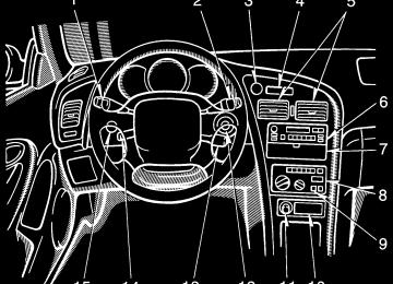
Instrument panel overview
1. Side vent 2. Side defroster outlet 3. 4. Personal lights 5. Electric moon roof switches and
Instrument cluster
interior lights
6. Glovebox 7. Power window switch and
power door lock switch
8. Ashtray 9. Cup holder 10. Parking brake lever 11. Manual transmission gear shift lever or automatic transmission selector lever
12. Lower vent 13. Hood lock release lever 14. Power window switches and power
door lock switch
15. Power rear view mirror control
switch (with power windows)
1. Headlight and turn signal switch 2. Wiper and washer switches 3. Emergency flasher switch 4. Clock 5. Center vents 6. Car audio 7. Miscellany box 8. Air conditioning controls 9. Rear window and outside rear view
mirror defoggers switch
10. Coupe and liftback—
Power rear view mirror control switch (without power windows) Convertible— Convertible top control switch and quarter window control switches
Ignition switch
11. Cigarette lighter 12. 13. Cruise control switch 14. Tilt steering lock release lever 15.
Instrument panel light control knob
Instrument cluster overview
1. Service reminder indicators or
indicator lights
2. Tachometer 3. Odometer and two trip meters
4. Engine coolant temperature gauge 5. Fuel gauge 6. Trip meter
7. Trip meter reset knob 8. Speedometer
Indicator symbols on the instrument panel
Brake system warning light *1
Seat belt reminder light*1
Discharge warning light*1
Low oil pressure warning light*1
Malfunction indicator light*1
Low fuel level warning light *1
Anti-lock brake system warning light *1
Open door warning light*1
SRS airbag warning light*1
Turn signal indicator lights
Headlight high beam indicator light
Over-drive indicator light
Cruise control indicator light*2
*1: For details, see “Service reminder indicators and warning
buzzers” in Chapter 1-5. If this light flashes, see “Cruise control” in Chapter 1-6.
*2:
Part 1
OPERATION OF INSTRUMENTS AND CONTROLS—Keys
Chapter 1-2
Keys and Doors(cid:1) Keys (cid:1) Side doors (cid:1) Power windows (cid:1) Trunk lid/Back door (cid:1) Hood (cid:1) Fuel tank cap (cid:1) Electric moon roof (cid:1) Convertible top
Your vehicle is supplied with two kinds of key. 1 Master key—This key works in every lock. 2 Subkey—This key is for side doors. To protect things locked in the glovebox, trunk or luggage compartment when you have your vehicle parked, leave the sub- key with the attendant. Since the side doors, trunk lid and back door can be locked without a key, you should always carry a spare master key in case you accidentally lock your keys in- side the vehicle.
KEY NUMBER PLATE Your key number is shown on the plate. Keep the plate in a safe place such as your wallet, not in the vehicle. If you should lose your keys of if you need additional keys, duplicates can be made by a Toyota dealer using the key number. You should also put a copy of the key number with your important papers.
Side doors
Driver’s side
LOCKING AND UNLOCKING WITH KEY Insert the key into the keyhole and turn it. To lock: Turn the key forward. To unlock: Turn the key backward. Both side doors lock and unlock simulta- neously with either side door. In the driv- er’s door lock, turning the key once will un- lock the driver’s door and twice in succession will unlock both side doors si- multaneously.
LOCKING AND UNLOCKING WITH IN- SIDE LOCK KNOB Move the lock knob. To lock: Push the knob forward. To unlock: Pull the knob backward. Closing the side door with the lock knob in the lock position will also lock the side door. Be careful not to lock your keys in the vehicle. Vehicles with power door lock system— The side door cannot be locked if you leave the key in the ignition switch.
Passenger’s side
LOCKING AND UNLOCKING WITH POWER DOOR LOCK SWITCH Push the switch. To lock: Push the switch on the front side. To unlock: Push the switch on the rear side Both doors lock or unlock simultaneously.
CAUTION
Before driving, be sure that the side doors are closed and locked, espe- cially when small children are in the vehicle. Along with the proper use of seat belts, locking the side doors helps prevent the driver and passen- gers from being thrown out from the vehicle during an accident. It also helps prevent the side doors from being opened unintentionally.
Power windows— —Power window precautions
—Side windows
CAUTION
To avoid serious personal injury, you must do the following. (cid:1) Always make sure the head, hands and other parts of the body of all occupants are kept completely in- side the vehicle before you close the power windows. If someone’s neck, head or hands gets caught in a closing window, it could result in serious in a serious injury. When anyone closes the power windows, be sure that they operate the win- dows safely.
(cid:1) When small children are in the ve- hicle, never let them use the power window switches without supervi- sion. Use the window lock button to prevent them from making unex- pected use of the switches.
(cid:1) Never leave small children alone in the vehicle, especially with the ignition key still inserted. They could use the power window switches and get trapped in a win- dow. Unattended children can be- come involved in serious acci- dents.
The windows can be operated with the switch on each side door. The power windows work when the igni- tion switch is in the “ON” position. Howev- er, if both side doors are closed, they work for 60 seconds even after the ignition switch is turned off. They stop working when either side door is opened. OPERATING THE DRIVER’S WINDOW Use the switch on the driver’s door. Normal operation: The window moves as long as you hold the switch. To open: Lightly pull down the switch. To close: Push up the switch.
OPERATING THE PASSENGERS’ WIN- DOWS Use the switch on each passenger’s door. The driver’s door also has a switch that controls the passengers’ window. The window moves as long as you hold the switch. To open: Pull down the switch. To close: Push up the switch. If you push in the window lock button on the driver’s door, the passenger’s window cannot be operated. Convertible models—The windows lock button also locks the quarter windows.
For front passenger’s use
Automatic operation (to open only): Pull the switch completely down and then release it. The window will fully open. To stop the window partway, lightly push the switch up and then release it.
10
For driver’s use
—Quarter windows (convertible)
Trunk lid (coupe and convertible)/ Back door (liftback)—
—Lock release lever
The windows can be operated with switches on the center console. The windows move as long as you hold the switch. To open: Push on the lower side of the switch. To close: Push on the upper side of the switch.
To open the trunk lid or back door from the outside, insert the master key and turn it clockwise. See “Luggage stowage precautions” in Part 2 for precautions to observe in load- ing luggage. To close the trunk lid or back door, lower it and press down on it. After closing the trunk lid or back door, try pulling it up to make sure it is securely closed.
CAUTION
To open the trunk lid or back door from the driver’s seat, pull up on the lock release lever.
Keep the trunk lid or back door closed while driving. This not only keeps from being thrown out but also prevents ex- haust gases from entering the ve- hicle.
luggage
the
11
—Luggage security system
Hood
2. After closing the trunk lid or back door, insert the master key and turn it counterclockwise to deactivate the lock release lever. After closing the trunk lid or back door, try pulling it up to make sure it is securely locked.
To open the hood, do the following. 1. Pull the hood lock release lever. The hood will spring up slightly.
This system deactivates the lock re- lease lever so that things locked in the trunk or luggage compartment can be protected. 1. (Except convertible) Push down the security lock levers to lock the rear seatbacks. After locking the rear seatbacks, try fold- ing them down to make sure they are se- curely someone could get into the trunk or luggage compartment by folding down a rear seat.
locked—otherwise,
12
Fuel tank cap
2. In front of the vehicle, pull up on the auxiliary catch lever and lift the hood.
3. Hold the hood open by inserting the support rod into the slot. Before closing the hood, check to see that you have not forgotten any tools, rags, etc. and return the support rod to its clip- this prevents rattles. Then lower the hood and make sure it locks into place. If neces- sary, press down gently on the front edge to lock it.
CAUTION
After inserting the support rod into the slot, make sure the rod supports the hood security.
1. To open the fuel filler door, pull the lever up.
CAUTION
(cid:1) Do not smoke, cause sparks or al- low open flames when refuelling. The fumes are flammable.
(cid:1) When opening the cap, do not re- In hot move the cap quickly. weather, fuel under pressure could cause injury by spraying out of the filler neck if the cap is sud- denly removed.
13
Electric moon roof
CAUTION
(cid:1) Make sure the cap is tightened se- curely to prevent fuel spillage in case of an accident.
(cid:1) Use only a genuine Toyota fuel tank cap for replacement. It has a built- in check valve to reduce fuel tank vacuum.
2. To remove the fuel tank cap, turn the cap slowly counterclockwise, then pause slightly before removing it. Af- ter removing the cap, hang it on the cap hanger. It is not unusual to hear a slight swoosh when the cap is opened. When installing, turn the cap clockwise till you hear a click.
14
Sliding operation
Tilting operation
To operate the moon roof, use the switches beside the interior light. The moon roof works when the ignition switch is in the “ON” position. However, if both side doors are closed, it works for 60 seconds even after the ignition switch is turned off. It stops working when either side door is opened. Sun shade operation— The sun shade can be opened or closed by hand. Sliding operation— To open: Push the switch on the “SLIDE” side. The sun shade will be opened together with the roof. To close: Push the switch on the opposite side of the “SLIDE” side. As a precaution when closing, the roof stops at the three-quarters closed posi- tion before fully closing. Therefore, re- lease the switch and then push it again to close it completely. Tilting operation— To tilt up: Push the switch on the “UP” side. To lower: Push the switch on the ”opposite of the “UP” side. You may stop the moon roof at any desired position. The roof will move while the switch is being pushed and stop when released.
CAUTION
To avoid serious personal injury, you must do the following. (cid:1) When the vehicle is moving, always keep the head, hands and other parts of the body of all occupants away from the roof opening. Other- wise, you could be seriously in- jured if the vehicle stops suddenly or if the vehicle is involved in an ac- cident.
(cid:1) Always make sure nobody places his/her head, hands and other parts of the body in the roof opening be- fore you close the roof . If some- one’s neck, head or hands gets caught in the closing roof, it could result in a serious injury. When any- one closes the roof, first make sure it is safe to do so.
(cid:1) Never leave small children alone in the vehicle, especially with the igni- tion key still inserted. They could use the moon roof switches and get trapped in the roof opening. Unat- tended children can become in- volved in serious accidents.
(cid:1) Never sit on top of the vehicle
around the roof opening.
Convertible top— —Convertible top precautions
CAUTION
(cid:1) When raising or lowering the con- vertible top, keep hands clear from the hinges of the top side rails and any part of the top linkage.
(cid:1) The vehicle should never be driv- en with the convertible top partial- ly lowered. Make sure the top has been either fully latched to the windshield frame or fully lowered before driving.
NOTICE
(cid:3)Make sure there are no items or packages between the rear seat- back and the convertible top stor- age area when raising or lowering the convertible top. Even small items may interfere with convert- ible top operation and can cause damage.
(cid:3)Do not sit or place excessive weight on the convertible top; when the top is up or down, dam- age to the top may result.
15
—Lowering the convertible top
2. Push and hold the convertible top control switch on the “OPEN” side un- til the convertible top is completely lowered. Raise the sun visor.
LOWERING THE CONVERTIBLE TOP The ignition switch must be in the “ON” position to operate the convertible top. 1. Lower all the side windows, quarter windows, and sun visors. Then pull the latch handles fully backward. Before operating, make sure the manual control switch is not in the “MANUAL” position. (See “If the convertible top does not raise or lower” in Part 4.)
(cid:3)Do not raise or lower the convert- ible top when the temperature is below 5(cid:2)C (41(cid:2) F), or damage to the top material or rear window may re- sult. If necessary to do so, warm the vehicle in a heated garage prior to operating the convertible top mechanism.
(cid:3)Do not lower the convertible top if the top is damp or wet. Possible in- terior water damage, water stains or mildew of the top material may result.
(cid:3)When the convertible top is com- pletely lowered, keep the rear win- dow defogger turned off to avoid damage to the convertible top.
16
4. Secure the top boot snaps to the ones on the quarter trim.
5. Attach the fastener tape on the top boot to that on the rear seatback.
INSTALLING THE TOP BOOT The top boot is used to cover and conceal the completely lowered convertible top. It is in the trunk, and is stored in a plastic bag. 3. Place the top boot over the lowered convertible top. Then tuck its outer edge under the body moldings.
17
—Raising the convertible top
REMOVING THE TOP BOOT 1. Push the top boot backward to sep- arate its fastener tape from the tape be- hind the rear seatback.
2. Release the top boot snaps from the quarter trim.
3. Pull out the outer edge of the top boot from under the body moldings. Put the removed top boot in the plastic bag and store it in the trunk.
18
RAISING THE CONVERTIBLE TOP The ignition switch must be in the “ON” position to operate the convertible top. 4. Lower the sun visors. Check that all the side windows and quarter win- dows are lowered. Then push and hold the convertible top control switch on the “CLOSE” side until top touches the windshield frame.
the
5. Push the latch handles fully forward till they are hooked. Visually check that the latch handles are fully seated in the strikers. Also, pull on the convertible top side rails to make sure the top is securely hooked. 6. Raise all the side windows, quarter windows, and sun visors.
19
20
Seats While the vehicle is being driven, all ve- hicle occupants should have the seatback upright, sit well back in the seat and prop- erly wear the seat belt provided.
CAUTION
(cid:1) Do not drive the vehicle unless the occupants are properly seated. Do not allow sitting on top of a folded- down seatback, or in the luggage compartment. Persons not proper- ly seated and not properly re- strained by seat belts can be se- verely injured in the event of emer- gency braking or a collision.
(cid:1) During driving, do not allow pas- sengers to stand up or move around between seats. Severe inju- ries can occur in the event of emer- gency braking or a collision.
Part 1
OPERATION OF INSTRUMENTS AND CONTROLS—Chapter 1-3
Seats, Seat belts, Steering wheel and Mirrors (cid:1) Seats (cid:1) Front seats (cid:1) Fold-down rear seat (cid:1) Head restraints (cid:1) Seat belts (cid:1) SRS airbags (cid:1) Child restraint (cid:1) Tilt steering wheel (cid:1) Outside rear view mirrors (cid:1) Anti-glare inside rear viewmirror
Front seats— —Seat adjustment precautions Adjust the driver’s seat so that the foot pedals, steering wheel and instrument panel controls are within easy reach of the driver.
CAUTION
(cid:1) Adjustments should not be made while the vehicle is moving, as the seat may unexpectedly move and cause the driver to lose control of the vehicle. (cid:1) When adjusting the seat, be careful not to hit the seat against a passen- ger or luggage. (cid:1) After adjusting the seat position, try sliding it forward and backward to make sure it is locked in position. (cid:1) After adjusting the seatback, exert body pressure to make sure it is locked in position. (cid:1) Do not put objects under the seats as they may interfere with the seat- lock mechanism or unexpectedly push up the seat position adjusting lever; the seat may suddenly move, causing the driver to lose control of the vehicle. (cid:1) While adjusting the seat, do not put your hands under the seat or near the moving parts. You may catch and injure your hands or fingers.
21
—Adjusting front seats
—Moving passenger’s seat for rear seat entry
1. SEAT POSITION ADJUSTING LE- VER Pull the lever up. Then slide the seat to the desired position with slight body pressure and release the lever. 2. SEATBACK ANGLE ADJUSTING LEVER Lean forward and pull the lever up. Then lean back to the desired angle and release the lever.
CAUTION
To reduce the risk of sliding under the lap belt during a collision, avoid reclining the seatback any more than needed. The seat belts provide maxi- mum protection in a frontal or rear collision when the driver and the passenger are sitting up straight and well back in the seats. If you are re- clined, the lap belt may slide past your hips and apply restraint forces directly to the abdomen. Therefore, in the event of a frontal collision, the risk of personal injury may increase with increasing recline of the seat- back. 3. DRIVER’S SEAT CUSHION ANGLE ADJUSTING KNOB Turn the knob either way.
For easy access to the rear seat, do this. 1. Lift the seatback angle adjusting lever or press the pedal behind the seatback. The seat will slide forward slightly. 2. Move the seat to the front-most posi- tion. After passengers are in, lift up the seat- back and return the seat until it locks.
22
Fold-down rear seat
CAUTION
(cid:1) After putting back the seat, try pushing the seat forward and rear- ward to make sure it is secured in place.
(cid:1) Never allow anyone to rest their foot on the release pedal while the vehicle is moving.
CAUTION
When returning the seatback to the upright position: (cid:1) Make sure the seat belts are not twisted or caught in the seatback and are arranged in the proper position for ready to use.
(cid:1) Make sure the seatback is securely locked by pushing forward and rearward on the top of the seat- back.
1. Pull up the seatback security lock lever 1 to the unlock position. 2. Pull up the lock release button 2. 3. Fold down the seatback. Each seatback may be folded separately. This will enlarge the trunk room (coupe) or luggage compartment (liftback) as far as the front seatbacks. See “Luggage stow- age precautions” in Part 2 for precautions to observe in loading luggage.
23
Head restraints
CAUTION
(cid:1) Adjust the top of the head restraint so that it is closest to the top of your ears.
(cid:1) After adjusting the head restraint, make sure it is locked in position. (cid:1) Do not drive with the restraints re-
moved.
For your safety, adjust the head re- straint before driving. To raise: Pull it up. To lower: Push it down while pressing the lock release button. On some models, you can also move the head restraint forward or backward. If such adjustment is desired, pull or push the head restraint. The head restraining is most effective when it is close to your head. Therefore, using a cushion on the seatback is not rec- ommended.
24
Seat belts— —Seat belt precautions Toyota strongly urges that the driver and passengers in the vehicle be properly re- strained at all times with the seat belts provided. Failure to do so could increase the chance of injury and/or the severity of injury in accidents. Child. Use a child restraint system ap- propriate for the child until the child be- comes large enough to properly wear the vehicle’s seat belts. See “Child restraint” for details. If a child is too large for a child restraint system, the child should sit in the rear seat and must be restrained using the vehicle’s seat belt. According to accident statistics, the child is safer when properly restrained in the rear seat than in the front seat. If a child must sit in the front seat, the seat belts should be worn properly. If an acci- dent occurs and the seat belts are not worn properly, the force of the rapid infla- tion of the airbag may cause serious injury to the child. Do not allow the child to stand up or kneel on either rear or front seats. An unre- strained child could suffer serious injury during emergency braking or a collision. Also, do not let the child sit on your lap. It does not provide sufficient restraint.
If the shoulder belt falls across the child’s neck or face, have the child sit slightly closer to the center of the vehicle so that the belt lays across the shoulder. Pregnant woman. Toyota recommends the use of a seat belt. Ask your doctor for specific recommendations. The lap belt should be worn securely and as low as possible over the hips and not on the waist. Injured person. Toyota recommends the use of a seat belt. Depending on the injury, first check with your doctor for specific recommendations.
CAUTION
Persons should ride in their seats properly wearing their seat belts whenever the vehicle is moving. Otherwise, they are much more like- ly to suffer serious bodily injury in the event of sudden braking or a col- lision. When using the seat belts, observe the following: (cid:1) Use the belt for only one person at a time. Do not use a single belt for two or more people—even chil- dren.
(cid:1) Avoid reclining the seatbacks too much. The seat belts provide maxi- mum protection when the seat- backs are in the upright position. (See the seat adjustment instruc- tions.)
(cid:1) Be careful not to damage the belt webbing or hardware. Take care that they do not get caught or pinched in the seat or doors.
(cid:1) Inspect the belt system periodical- ly. Check for cuts, fraying, and loose parts. Damaged parts should be replaced. Do not disassemble or modify the system
(cid:1) Keep the belts clean and dry. If they need cleaning, use a mild soap solution or lukewarm water. Never use bleach, dye, or abrasive clean- ers—they may severely weaken the belts.
(cid:1) Replace the belt assembly (includ- ing bolts) If it has been used in a se- vere impact. The entire assembly should be replaced even if damage is not obvious.
(cid:1) Front passenger’s seat only—Re- place the belt if the warning label under the sleeve can be seen. The warning label, “REPLACE BELT”, will appear if the belt receives a severe impact or other force.
25
—Seat belts
Adjust the seat as needed (front seats only) and sit up straight and well back in the seat. To fasten your belt, pull it out of the retractor and insert the tab into the buckle. You will hear a click when the tab locks into the buckle. The seat belt length automatically adjusts to you size and the seat position. The retractor will lock the belt during a sudden stop or on impact. It also may lock if you lean forward too quickly. A slow, easy motion will allow the belt to extend, and you can move around freely.
26
If the seat belt cannot be pulled out of the retractor, firmly pull the belt and release it. You will then be able to smoothly pull the belt out of the retractor. When a passenger’s shoulder belt is com- pletely extended and is then retracted even slightly, the belt is locked in that posi- tion and cannot be extended. This feature is used to hold the child restraint system securely. (For details, see “Child restraint” in this chapter.) To free the belt again, fully retract the belt and then pull the belt out once more.
CAUTION
(cid:1) After inserting the tab, make sure the tab and buckle are locked and that the belt is not twisted.
(cid:1) Do not insert coins, clips, etc. in the buckle as this may prevent you from properly latching the tab and buckle.
(cid:1) If the seat belt does not function normally, immediately contact your Toyota dealer. Do not use the seat until the seat belt is fixed. It cannot protect an adult occupant or your child from injury.
Adjust the position of the lap and shoulder belts Position the lap belt as low as possible on your hips—not your waist, then adjust it to a snug fit by pulling the shoulder portion upward through the latch plate.
CAUTION
(cid:1) High-positioned
lap belts and loose-fitting belts both could in- crease the chance of injury due to sliding under the lap belt during a collision. Keep the lap belt posi- tioned as low on as possible hips. (cid:1) For your safety, do not place the
shoulder belt under your arm.
To release the belt, press the buckle- release button and allow the belt to re- tract. If the belt does not retract smoothly, pull it out and check for kinks or twists. Then make sure it remains untwisted as it re- tracts.
—Seat belt extender If your seat belt cannot be fastened se- curely because it is not long enough, a personalized seatbelt extender is avail- able from your Toyota dealer free of charge. Please contact your local Toyota dealer so that the dealer can order the proper re- quired length for the extender. Bring the heaviest coat you expect to wear for prop- er measurement and selection of length. Additional ordering information is avail- able at your Toyota dealer.
CAUTION
When using the seat belt extender, observe the following. Failure to fol- low these instructions could result in less effectiveness of the seat belt restraint system in case of vehicle accident, increasing the chance of personal injury. (cid:1) Never use the seat belt extender if you can fasten the seat belt with- out it.
(cid:1) Remember that the extender pro- vided for you may not be safe when used on a different vehicle, or for another person or at a differ- ent seating position than the one originally intended for.
27
SRS airbags
CAUTION
(cid:1) After inserting the tab, make sure the tab and buckle are locked and that the seat belt extender is not twisted.
(cid:1) Do not insert coins, clips, etc. in the buckle as this may prevent you