- 2006 Toyota Camry Owners Manuals
- Toyota Camry Owners Manuals
- 1998 Toyota Camry Owners Manuals
- Toyota Camry Owners Manuals
- 2015 Toyota Camry Owners Manuals
- Toyota Camry Owners Manuals
- 2001 Toyota Camry Owners Manuals
- Toyota Camry Owners Manuals
- 2010 Toyota Camry Owners Manuals
- Toyota Camry Owners Manuals
- 2004 Toyota Camry Owners Manuals
- Toyota Camry Owners Manuals
- 2005 Toyota Camry Owners Manuals
- Toyota Camry Owners Manuals
- 1997 Toyota Camry Owners Manuals
- Toyota Camry Owners Manuals
- 2000 Toyota Camry Owners Manuals
- Toyota Camry Owners Manuals
- 2002 Toyota Camry Owners Manuals
- Toyota Camry Owners Manuals
- 2012 Toyota Camry Owners Manuals
- Toyota Camry Owners Manuals
- 1996 Toyota Camry Owners Manuals
- Toyota Camry Owners Manuals
- 2003 Toyota Camry Owners Manuals
- Toyota Camry Owners Manuals
- 2009 Toyota Camry Owners Manuals
- Toyota Camry Owners Manuals
- 2008 Toyota Camry Owners Manuals
- Toyota Camry Owners Manuals
- Download PDF Manual
-
backs are in the upright position. (See the seat adjustment instruc- tions.)
(cid:1) Be careful not to damage the belt webbing or hardware. Take care that they do not get caught or pinched in the seat or doors.
(cid:1) Inspect the belt system periodical- ly. Check for cuts, fraying, and loose parts. Damaged parts should be replaced. Do not disassemble or modify the system.
—Front seat belts and rear outside seat belts
Seat belts with a seat belt hanger— Make sure that the seat belt hanger is secured in raised position. If it is not, be sure to raise the seat belt hanger until it locks in position. You will hear a click when the seat belt hanger locks in position.
Adjust the seat as needed (front seats only) and sit up straight and well back in the seat. To fasten your belt, pull it out of the retractor and insert the tab into the buckle. You will hear a click when the tab locks into the buckle. The seat belt length automatically adjusts to your size and the seat position. The retractor will lock the belt during a sudden stop or on impact. It also may lock if you lean forward too quickly. A slow, easy motion will allow the belt to extend, and you can move around freely. If the seat belt cannot be pulled out of the retractor, firmly pull the belt and release it. You will then be able to smoothly pull the belt out of the retractor.
When a passenger’s shoulder belt is com- pletely extended and is then retracted even slightly, the belt is locked in that posi- tion and cannot be extended. This feature is used to hold the child restraint system securely. (For details, see “Child restraint” in this chapter.) To free the belt again, fully retract the belt and then pull the belt out once more.
CAUTION
(cid:1) After inserting the tab, make sure the tab and buckle are locked and that the belt is not twisted.
(cid:1) Do not insert coins, clips, etc. in the buckle as this may prevent you from properly latching the tab and buckle.
(cid:1) If the seat belt does not function normally, immediately contact your Toyota dealer.
31
CAUTION
Always make sure the shoulder belt is positioned across the center of your shoulder. The belt should be kept away from your neck, but not falling off your shoulder. Failure to do so could reduce the amount of protection in an accident and in- crease the chance of injury.
Adjust the position of the lap and shoulder belts. Position the lap belt as low as possible on your hips—not on your waist, then adjust it to a snug fit by pulling the shoulder por- tion upward through the latch plate.
CAUTION
(cid:1) High-positioned
lap belts and loose-fitting belts both could in- crease the chance of injury due to sliding under the lap belt during an accident. Keep the lap belt as low on your hip bone as possible. (cid:1) For your safety, do not place the
shoulder belt under your arm.
Seat belts with an adjustable shoulder anchor— Adjust the shoulder anchor position to your size. To raise the anchor position, push the an- chor up. To lower the anchor position, pull the knob and slide the anchor down. After adjustment, make sure the anchor is locked in position.
32
—Rear center seat belt
CAUTION
(cid:1) After inserting the tab, make sure the tab and buckle are locked and that the belt is not twisted.
(cid:1) Do not insert coins, clips, etc. in the buckle as this may prevent you from properly latching the tab and buckle.
(cid:1) If the seat belt does not function normally, immediately contact your Toyota dealer.
To release the belt, press the buckle- release button and allow the belt to re- tract. If the belt does not retract smoothly, pull it out and check for kinks or twists. Then make sure it remains untwisted as it re- tracts.
Sit up straight and well back in the seat. To fasten your belt, insert the tab into the buckle. You will hear a click when the tab locks into the buckle. If the belt is not long enough for you, hold the tab at a right angle to the belt and pull on the tab.
33
—Stowing the rear seat belts (wagon)
To release the belt, press the buckle- release button.
The rear seat belts can be stowed when not in use. Seat belts must be stowed before you fold the seatback. (See “Rear seats—Fold- down rear seat” in this chapter.)
Remove excess length of the belt and adjust the belt position. To shorten the belt, pull the free end of the belt. Position the lap belt as low as possible on your hips—not on your waist, then adjust it to a snug fit.
CAUTION
High-positioned and loose-fitting lap belts could increase the chance of injury due to sliding under the lap belt during an accident. Keep the lap belt as low on your hip bone as pos- sible.
34
—Stowing the third seat belts (wagon)
The third seat belts can be stowed when not in use. Seat belts must be stowed before you fold the seatback. (See “Rear seats—Take- down third seat” in this chapter.)
—Seat belt extender If your seat belt cannot be fastened se- curely because it is not long enough, a personalized seat belt extender is avail- able from your Toyota dealer free of charge. Please contact your local Toyota dealer so that the dealer can order the proper re- quired length for the extender. Bring the heaviest coat you expect to wear for prop- er measurement and selection of length. Additional ordering information is avail- able at your Toyota dealer.
CAUTION
When using the seat belt extender, observe the following. Failure to fol- low these instructions could result in less effectiveness of the seat belt restraint system in case of vehicle accident, increasing the chance of personal injury. (cid:1) Never use the seat belt extender if you can fasten the seat belt with- out it.
(cid:1) Remember that the extender pro- vided for you may not be safe when used on a different vehicle, or for another person or a different seating position than the one orig- inally intended for.
To connect the extender to the seat belt, insert the tab into the seat belt buckle so that the “PRESS” signs on the buckle-release buttons of the ex- tender and the seat belt are both facing outward as shown. You will hear a click when the tab locks into the buckle. When releasing the seat belt, press on the buckle-release button on the extender, not on the seat belt. This helps prevent damage to the vehicle interior and extend- er itself. When not in use, remove the extender and store in the vehicle for future use.
35
SRS airbags
CAUTION
(cid:1) After inserting the tab, make sure the tab and buckle are locked and that the seat belt extender is not twisted.
(cid:1) Do not insert coins, clips, etc. in the buckle as this may prevent you from properly latching the tab and buckle.
(cid:1) If the seat belt does not function immediately contact
normally, your Toyota dealer.
36
The SRS (Supplemental Restraint Sys- tem) airbags are designed to provide further protection to the driver and front passenger when added to the pri- mary protection provided by the seat belts. In response to a severe frontal impact, the SRS airbags work together with the seat belts to prevent or reduce injury by inflat- ing, in order to decrease the likelihood of the driver’s or front passenger’s head or chest directly hitting the steering wheel or dashboard. The passenger airbag is acti- vated even with no passenger in the front seat.
This indicator comes on when the ignition key is turned to the “ACC” or “ON” position. It goes off after about 6
seconds. This means the SRS airbags are operating properly. The SRS airbag warning light system monitors the front airbag sensors, center airbag sensor assembly, inflators, warn- ing light, interconnecting wiring and power sources.However, this threshold velocity will be considerably higher if the vehicle strikes an object, such as a parked vehicle or sign pole, which can move or deform on im- pact, or if it is involved in an underride col- lision (a collision in which the nose of the vehicle “underrides”, or goes under, the bed of a truck). It is possible with collision severity at the marginal level of airbag sensor detection and activation that only one of your ve- hicle’s two airbags will deploy. For your safety, be sure to always wear your seat belts.
The SRS airbag system is designed to activate in response to a severe frontal impact within the shaded area be- tween the arrows in the illustration. The SRS airbags will deploy if the severity of the impact is above the designed threshold level, comparable to an approxi- mate 20 km/h (14 mph) collision when im- pacting straight into a fixed barrier that does not move or deform. If the severity of the impact is below the above threshold level, the SRS airbags may not deploy.
The SRS airbags are not designed to inflate if the vehicle is subjected to a side or rear impact, if it rolls over, or if it is involved in a low-speed frontal collision.
37
When the airbags inflate, they produce a fairly loud noise and release some smoke along with the nitrogen gas. This is not harmful and does not indicate a fire. Be sure to wash off any residue as soon as possible to prevent minor skin irritation. Deployment of the airbags happen in a fraction of a second, so the airbags must inflate with considerable force. While the system is designed to reduce serious inju- ries, it may also cause minor burns or abrasions and swellings. Parts of the airbag module (steering wheel hub, dashboard) may be hot for several minutes, but the airbags them- selves will not be hot. The airbags are de- signed to inflate only once. A crash severe enough to inflate the air- bags may break the windshield as the ve- hicle buckles. In vehicles with a passen- ger airbag the windshield may also be damaged by absorbing some of the force of the inflating airbag.
CAUTION
(cid:1) The SRS airbag system is de- signed only as a supplement to the primary protection of the seat belt systems of the driver and front passenger. The front seat oc- cupants are particularly suscepti- ble to injury if they do not wear their seat belts; when sudden braking or a collision occurs, they may be thrown forward. To obtain further protection in an accident, the driver and all passengers in the vehicle should always wear their seat belts when driving. For instructions and precautions con- cerning the seat belt system, see “Seat belts” in this chapter.
(cid:1) A baby or small child who is too small to use a seat belt should be properly secured in a rear seat us- ing a child restraint system.
The center airbag sensor assembly con- sists of a safing sensor and center airbag sensor. In a severe frontal impact, sensors detect deceleration and the system triggers the airbag inflators. Then a chemical reaction in the inflators momentarily fills the air- bags with non-toxic nitrogen gas to help restrain the forward motion of the occu- pants.
38
(cid:1) Do not use a rear-facing child re- straint system in the front seat be- cause the force of the rapid infla- tion of the passenger airbag may cause severe injury to the child. Vehicles with a passenger airbag display a caution label on the pas- senger side instrument panel as shown above to remind you not to install a rear-facing child restraint system on the front seat.
(cid:1) When using a
forward-facing child restraint system in the front seat, the seat must be moved as far back as possible. For instructions concerning the installation of a child restraint system, see “Child restraint” in this chapter.
(cid:1) Do not sit on the edge of the seat or lean over the dashboard when the vehicle is in use. The airbags inflate with considerable speed and force; you may be severely in- jured. Sit up straight and well back in the seat, and always use your seat belt.
39
(cid:1) Do not modify, remove or open any component or wiring, such as the steering wheel, column cover, front passenger airbag cover, front pas- senger airbag, center airbag sensor assembly or front airbag sensors. Doing any of these may cause sud- den SRS airbag inflation or disable the system, which could result in personal injury.
Failure to follow these instructions can result in severe injuries.
(cid:1) Do not allow a child to stand up, or to kneel on the front passenger seat. The airbag inflates with con- siderable speed and force; the child may be severely injured.
(cid:1) Do not hold a child on your lap or in your arms. Use a child restraint system in the rear seat. For in- structions concerning the instal- lation of a child restraint system, see “Child restraint” in this chap- ter.
(cid:1) Do not put objects on or in front of the dashboard or steering wheel pad that houses the airbag sys- tem. They might restrict inflation or cause personal injury as they are projected rearward.
40
NOTICE
Do not perform any of the following changes without consulting your Toyota dealer. Such changes can interfere with proper operation of the SRS airbag system in some cases. (cid:2)Installation of electronic items such as a mobile two-way radio, cassette tape player or compact disc player
(cid:2)Modification of the suspension
system
(cid:2)Modification of the front end
structure
(cid:2)Attachment of a grille guard (bull bar, kangaroo bar, etc.), snow- plow, winches or any other equip- ment to the front end
(cid:2)Repairs made on or near the front fenders, front and rear console, steering column, steering wheel or dashboard near the front pas- senger’s airbag
This SRS airbag system has a service re- minder indicator to inform the driver of op- erating problems. If either of the following conditions occurs, this indicates a mal- function of the airbags. Contact your To- yota dealer as soon as possible to service the vehicle. (cid:1) The light does not come on when the ignition key is turned to the “ACC” or “ON” position, or remains on.
(cid:1) The light comes on while driving.
In the following cases, contact your Toyo- ta dealer as soon as possible: (cid:1) The SRS airbags have been inflated. (cid:1) The front part of the vehicle (shaded in the illustration) was involved in an ac- cident not of the extent to cause the SRS airbags to inflate.
(cid:1) The pad section of the steering wheel front passenger airbag cover or (shaded in the illustration) is scratched, cracked, or otherwise damaged.
41
Child restraint— —Child restraint precautions Toyota strongly urges the use of child restraint systems for children small enough to use it. The laws of all fifty states in the U.S.A. and Canada now require the use of a child restraint system.
CAUTION
For effective protection in automo- bile accidents and sudden stops, children must be properly re- strained. Holding a child in your arms is not a substitute for a child restraint system. In an accident, the child can be crushed against the windshield, or between you and the vehicle’s interior if you are unre- strained.
42
—Child restraint system A child restraint system for a small child or baby must itself be restrained on the seat with either the lap belt or the lap portion of the lap/shoulder belt. The child restraint system should conform to the size of the child and properly fit the vehicle seat. For greater safety, the child restraint system should be installed in the rear seat. According to accident statistics, children are safer when properly re- strained in the rear seat than in the front seat.
CAUTION
Do not use child restraint system on the rear-facing third seat.
When installing a child restraint system, follow the instructions provided by the manufacturer of the system. General di- rections are also provided under the fol- lowing illustrations.
CAUTION
After installing the child restraint system, make sure it is secured in place. If it is not restrained securely, it may cause injury to the child in the event of a sudden stop or accident.
When not using the child restraint system, keep it secured with the seat belt or place it somewhere other than in passenger compartment. This will prevent it injuring passengers in the event of a sudden stop or accident. Your vehicle has anchors for securing the top strap of a child restraint system. The anchor nuts are welded beneath the sheet metal to permit installation of an anchor bracket for a child restraint system. To install an anchor bracket, use an 8 mm X 30 mm X 1.25 mm coarse thread metric bolt and a 15 mm (0.6 in.) spacer. Note that the bolts accompanying many child restraint systems are not metric. You can damage the anchor nuts on your vehicle if you force bolts with different thread into the anchor nuts. For instructions about how to install the anchor bracket, see “(C) TOP STRAP ANCHORS AND LOCATIONS” . If your child restraint system does not pro- vide any of the necessary parts, you can purchase the following items from your Toyota dealer. * CRS installation kit
(Part No. 04731-22012) —contains 1 bolt, 3 types of spacers and 1 locking clip.
* Bolt
(Part No. 91511-60830)
(A)INSTALLATION ON REAR SEAT CENTER (forward-facing rear seat only)
When installing a rear-facing child re- straint system, follow the same procedure as when installing a forward-facing child restraint system.
CAUTION
Do not use a rear-facing child re- straint system in the rear seat if it in- terferes with the lock mechanism of the front seats. This may cause se- vere injury to the child and front passenger in case of sudden brak- ing or a collision.
1. Fasten the center lap belt over the child restraint system following the in- structions provided by its manufactur- er.
CAUTION
(cid:1) After inserting the tab, make sure
the tab and buckle are locked.
(cid:1) Do not insert coins, clips, etc. in the buckle as this may prevent you from properly latching the tab and buckle.
(cid:1) If the seat belt does not function normally, immediately contact your Toyota dealer.
43
2. Make sure the belt is tight by pulling its free end while you firmly push down the child restraint system.
3. If your child restraint system requires the use of a top strap, latch the hook onto the anchor bracket and tighten the top strap.
44
CAUTION
Push and pull the child restraint system in different directions to be sure it is secure.
4. To remove the child restraint system, press the buckle-release button and un- hook the top strap.
(B) INSTALLATION ON REAR SEAT OUTSIDE (forward-facing rear seat only) When installing a rear-facing child re- straint system, follow the same procedure as when installing a forward-facing child restraint system.
45
1. Fasten the lap and shoulder belt over the child restraint system following the in- struction provided by its manufacturer. Keep the lap portion of the belt tight.
CAUTION
2. Fully extend the shoulder belt to put it in the lock mode.
(cid:1) After inserting the tab, make sure
the tab and buckle are locked.
(cid:1) Do not insert coins, clips, etc. in the buckle as this may prevent you from properly latching the tab and buckle.
(cid:1) If the seat belt does not function immediately contact
normally, your Toyota dealer.
CAUTION
Do not use a rear-facing child re- straint system in the rear seat if it in- terferes with the lock mechanism of the front seats. This may cause se- vere injury to the child and front passenger in case of sudden brak- ing or a collision.
46
3. Place the shoulder belt between the vehicle seatback and the child restraint system and allow it to retract. To hold the child restraint system securely, let the shoulder belt retract as far as it will go while firmly pushing down the child re- straint system.
4. if your child restraint system requires the use of a top strap, latch the hook onto the anchor bracket and tighten the top strap.
47
CAUTION
Make sure the seat belt is securely locked. Also make sure the child re- straint system is secure by pushing and pulling it in different directions.
5. To remove the child restraint system, press the buckle-release button and al- low the belt to retract. Unlock the top strap.
(C) TOP STRAP ANCHORS AND LOCATIONS Sedan and coupe—On the filler panel behind the rear seat a. Make an anchor hole in the filler panel With plugs: Take out the plug. Without plugs: Find the hole in the filler panel by running your fingers across the filler panel trim at the locations shown in the illustration. Then cut out the covering directly above the hole in the filler panel. b. Insert a 15 mm (0.6 in.) spacer and tighten down the anchor bracket for your child restraint system with a bolt. Torque the bolt to 16.5—24.7 N⋅m (1.68—2.52
kgf⋅m, 12.2—18.2 ft⋅lbf).48
To comply with Canada Motor Vehicle Safety Standards, vehicles sold in Cana- da are provided with a bracket set in the glovebox, designed for use with any of the 3 anchor locations shown in the illustra- tion.
Wagon—On the rear trim a. Remove the rear trim and unplug the connector of luggage compartment light. b. Using the illustration as a guide, make hole on the center of the cross mark in the trim. Connect the connector of the lug- gage compartment light and install the trim.
Insert a 15 mm (0.6 in.) spacer and c. tighten down the anchor bracket for your child restraint system with a bolt. Torque the bolt to 16.5—24.7 N⋅m (1.68—2.52
kgf⋅m, 12.2—18.2 ft⋅lbf). To comply with Canada Motor Vehicle Safety Standards, vehicles sold in Cana- da are provided with a bracket set in the glovebox, designed for use with any of the 3 anchor locations shown in the illustra- tion.49
(cid:1) When using a
forward-facing child restraint system, move the seat as far back as possible.
1. Fasten the lap and shoulder belt over the child restraint system following the in- struction provided by its manufacturer. Keep the lap portion of the belt tight.
CAUTION
(cid:1) After inserting the tab, make sure
the tab and buckle are locked.
(cid:1) Do not insert coins, clips, etc. in the buckle as this may prevent you from properly latching the tab and buckle.
(cid:1) If the seat belt does not function normally, immediately contact your Toyota dealer.
(D) INSTALLATION ON FRONT SEAT
CAUTION
(cid:1) Do not use a rear-facing child re- straint system in the front seat be- cause the force of the rapid infla- tion of the passenger airbag may cause severe injury to the child. Vehicles with a passenger airbag display a caution label on the pas- senger side instrument panel as shown above to remind you not to install a rear-facing child restraint system on the front seat.
50
2. Fully extend the shoulder belt to put in the lock mode.
3. Place the shoulder belt between the vehicle seatback and the child restraint system and allow it to retract. To hold the child restraint system securely, let the shoulder belt retract as far as it will go while firmly pushing down the child re- straint system.
4. If your child restraint system requires the use of a top strap, latch the hook onto the tab of the rear center belt and tighten the top strap.
51
Tilt steering wheel
CAUTION
Make sure the seat belt is securely locked. Also make sure the child re- straint system is secure by pushing and pulling it in different directions.
5. To remove the child restraint system, press the buckle-release button and al- low the belt to retract. Unhook the top strap.
To change the steering wheel angle, hold the steering wheel, pull up the lock release lever, tilt the steering wheel to the desired angle and release the lever. When the steering wheel is in a low posi- tion, it will spring up as you release the lock release lever.
CAUTION
(cid:1) Do not adjust the steering wheel
while the vehicle is moving.
(cid:1) After adjusting the steering wheel, try moving it up and down to make sure it is locked in position.
52
Outside rear view mirrors—
—Rear view mirror remote control
—Power rear view mirror control
Adjust the mirror so you can see the side of your vehicle in the mirror. Be careful when judging the size or dis- tance of any object seen in the outside rear view mirror on the passenger’s side. It is a convex mirror with a curved surface. Any object seen in a convex mirror will look smaller and farther away than when seen in a flat mirror.
To adjust the rear view mirror, simply operate the control lever.
NOTICE
If ice should jam the mirror, do not operate the control or scrape the mirror face. Use a spray de-icer to free the mirror.
To adjust a power rear view mirror, first place the master switch at “L” (left) or “R” (right) depending on which mirror needs adjusting, then push the con- trol switch in the desired direction. If the engine is not running, the key must be in the “ACC” position. NOTICE
If ice should jam the mirror, do not operate the control or scrape the mirror face. Use a spray de-icer to free the mirror.
53
Anti-glare inside rear view mirror
Vanity mirrors
Pull the lever toward you to reduce glare from the headlights of the ve- hicle behind you during night driving. Before adjusting the mirror to the position with most clarity, push the day-night change lever away from you (daylight driving position). Remember that by reducing glare you also lose some rear view clarity.
To use the vanity mirrors, swing down the sun visor and open the cover. On some models, the vanity light comes on when you open the cover.
54
Part 1
OPERATION OF INSTRUMENTS AND CONTROLS—Chapter 1-4
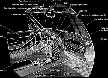
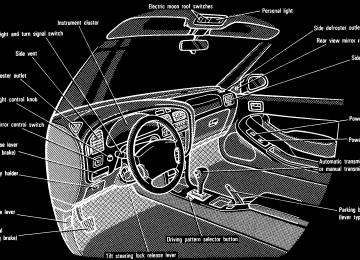
Lights, Wipers and Defogger(cid:1) Headlights and turn signals (cid:1) Emergency flashers (cid:1) Instrument panel light control (cid:1) Interior light (cid:1) Ignition switch light (cid:1) Personal light (cid:1) Luggage compartment light (cid:1) Windshield wipers and washer (cid:1) Rear window wipers and washer (cid:1) Rear window defogger
Headlights and turn signals
To turn on the lights on, twist the knob on end of the lever. Daytime running light system (Canada only)—The headlights turn on when the parking brake is released with the engine started, even with the light switch in the “OFF” position. They will not go off until the ignition switch is turned off. To turn on the other exterior lights and in- strument panel lights, twist the knob to the first clickstop. Under the daytime running light system, the headlights turn on at reduced intensi- ty. Twist the knob to the second clickstop to turn to full intensity for driving at night.
FIRST CLICKSTOP: Only the parking, tail, license plate, side marker and instru- ment panel lights turn on. SECOND CLICKSTOP: The headlights also turn on. The lights automatically turn off when the driver’s door is opened with the ignition turned off. To turn them on again, turn the key to the “ON” position or actuate the headlight switch. If you are going to park for over one week, make sure the head- light switch is off.
NOTICE
To prevent the battery from being discharged, do not leave the lights on for a long period when the engine is not running.
55
Emergency flashers
For high beam, push the lever away from you. Pull it toward you for low beam. For the headlight flasher, pull it further back. A blue light in the instrument panel indi- cates high beam is on. The headlight flasher works even when the headlight switch is off.
For signaling turns, move the lever up or down in the conventional manner. The key must be in the “ON” position. The turn signal is self-cancelling after a turn, but after a lane change, you may have to cancel it by hand. You can signal a lane change by moving the turn signal lever partway and holding it there. If the green light in the instrument panel flashes faster than normal, it indicates that the front or rear turn signal bulb has burned out.
To turn on the emergency flashers, push the switch. All the turn signal lights will flash. Turn on the emergency flashers to warn other drivers if your vehicle must be stopped where it might be a traffic hazard. Always pull as far off the road as possible. The turn signal light switch will not work when the emergency flashers are operat- ing.
NOTICE
To prevent the battery from being discharged, do not leave the switch on longer than necessary when the engine is not running.
56
Instrument panel light control
Interior light
Ignition switch light
To adjust the brightness of the instru- ment panel lights, turn the knob.
To turn on the interior light, slide the switch. With the switch in the “DOOR” position, the light comes on when any of the side doors are opened and goes out when they are closed. On some models, the light re- mains on for a certain time after all of the side doors are closed.
For easy access to the ignition switch, the ignition switch light comes on when any of the side doors are opened. The light remains on for a certain time af- ter all of the side doors are closed.
57
Personal light
Luggage compartment light (wagon)
Windshield wipers and washer (with interval adjuster)
To turn on the personal light, push the switch. To turn it off, push the switch once again.
To turn the luggage compartment light on, open the back door and push the switch. Closing the back door will turn the light off.
To turn the wipers on, move the lever. To make the washer squirt, push the button on the end of the lever. The key must be in the “ON” position. The wipers will operate at intervals when the lever is in the “INT” position. With the lever in this position, the wipers can be ad- justed to operate at intervals of 3 to 12
seconds depending on the interval adjust- er setting between “S” and “F”. If a single wipe is desired in mist, pull the lever toward you and release it. Also, the wipers will automatically operate a couple of times after the washer squirts even with the lever in the “OFF” position.58
In cold weather, warm the windshield with the defroster before using the washer. This will help prevent icing, which could block your vision.
NOTICE
Do not operate the wipers if the windshield is dry. It may scratch the glass.
If the washer does not work, check to see whether the washer tank is empty. For in- formation on adding washer fluid, see “Adding washer fluid” in Chapter 7-3. In cold weather, warm the windshield with the defroster before using the washer. This will help prevent icing, which could block your vision.
NOTICE
Do not operate the wipers if the windshield is dry. It may scratch the glass.
Windshield wipers and washer (without interval adjuster)
To turn the wipers on, move the lever. To make the washer squirt, push the button on the end of the lever. The key must be in the “ON” position. The wipers will operate at intervals when the lever is in the “INT” position. If a single wipe is desired in mist, pull the lever toward you and release it. If the washer does not work, check to see whether the washer tank is empty. For in- formation on adding washer fluid, see “Adding washer fluid” in Chapter 7-3.
59
Rear window wipers and washer (wagon)
Rear window defogger
NOTICE
Do not operate the rear wipers if the rear window is dry. It may scratch the glass.
To turn the rear wipers and washers on, twist the knob at the end of the lever. The key must be in the “ON” position. The wipers will operate at intervals when the knob is in the “INT” position. The washer squirts at the two marked knob positions. The knob will automatical- ly return from these positions when it is re- leased. If the washer does not work, check to see whether the washer tank is empty. For in- formation on adding washer fluid, see “Adding washer fluid” in Chapter 7-3.
60
To defog or defrost the rear window, push the switch. The key must be in the “ON” position. The thin heater wires on the inside of the rear window will quickly clear the sur- faces. An indicator light will illuminate to indicate the defogger is operating. Push the switch once again to turn the de- fogger off. The system will automatically shut off af- ter the defogger has operated about 15
minutes.Make sure you turn the defogger off when the window is clear. Leaving the defogger on for a long time could cause the battery to discharge, especially during stop-and- go driving. The defogger is not designed for drying rain water or for melting snow.
NOTICE
When cleaning the inside of the rear window, be careful not to scratch or damage the heater wires.
61
62
Part 1
OPERATION OF INSTRUMENTS AND CONTROLS—Chapter 1-5
Gauges, Meters and Service reminder indicators(cid:1) Fuel gauge (cid:1) Engine coolant temperature
gauge
(cid:1) Tachometer (cid:1) Odometer and trip meter (cid:1) Service reminder indicators
and warning buzzers
Fuel gauge
If the fuel tank is completely empty, the malfunction indicator lamp comes on. Fill the fuel tank immediately. The indicator lamp goes off after driving several times. If the indicator lamp does not go off, contact your Toyota dealer as soon as possible.
The gauge works when the ignition switch is on and indicates the approxi- mate quantity of fuel remaining in the tank. It is a good idea to keep the tank over 1/4
full. This fuel gauge has a non-return type needle which remains at the last indicated position when the ignition switch is turned off. If the level approaches “E” or the low fuel level warning light comes on, fill the fuel tank as soon as possible.63
Engine coolant temperature gauge
Tachometer
NOTICE
(cid:2)Do not remove the thermostat in the engine cooling system as this may cause the engine to overheat. The thermostat is designed to control the flow of coolant to keep the temperature of the engine within the specified operating range.
(cid:2)Do not continue driving with an overheated engine. See “If your vehicle overheats” in Part 4.
The gauge indicates the engine cool- ant temperature when the ignition switch is on. The engine operating temperature will vary with changes in weather and engine load. If the needle points to the red zone or high- er, stop your vehicle and allow the engine to cool. Your vehicle may overheat during severe operating conditions, such as: (cid:1) Driving up a long hill on a hot day. (cid:1) Reducing speed or stopping after high
speed driving. Idling for a long period with the air con- ditioning on in stop-and-go traffic.
(cid:1)
(cid:1) Towing a trailer.
64
tachometer
indicates engine The speed in thousands of rpm (revolu- tions per minute). Use it while driving to select correct shift points and to prevent engine lugging and overrev- ving. Driving with the engine running too fast causes excessive engine wear and poor fuel economy. Remember, in most cases the slower the engine speed, the greater the fuel economy.
NOTICE
Do not let the indicator needle get into the red zone. This may cause severe engine damage.
Odometer and trip meter
Service reminder indicators and warning buzzers
The odometer records the total dis- tance the vehicle has been driven. The trip meter may be set to zero to record the distance on each trip. To reset the trip meter, press the trip meter reset knob. The black digits on white indicate tenths of kilometers or miles.
65
(a) Brake System Warning Light This light has the following functions: Parking brake reminder If this light is on, make sure the parking brake is fully released. The light should go off. Low brake fluid level warning If this light comes on and stays on while you are driving, slow down and pull off the road. Then stop the vehicle carefully. There may be a problem somewhere in the brake system. Check the fluid level of the see-through reservoir. To make sure the parking brake has not caused the warning light to come on, check to see that the parking brake is fully released. If the brake fluid level is low... At a safe place, test your brakes by start- ing and stopping.
(cid:1)
(cid:1)
If you judge that the brakes still work adequately, drive cautiously to your nearest dealer or shop for repairs. If the brakes are not working, have the vehicle towed in for repairs. (For tow- ing information, see Part 4.)
CAUTION
It is dangerous to continue driving normally when the brake fluid level is low.
66
If the brake fluid level is correct... Have the warning system checked by your Toyota dealer. (b) Seat Belt Reminder Light and Buzzer Once the ignition key is turned to “ON” or “START”, the reminder light and buzzer come on if the driver’s seat belt is not fas- tened. Unless the driver fastens the belt, the light stays on and the buzzer stops af- ter about 4 to 8 seconds. (c) Discharge Warning Light This light warns that the battery is being discharged. If it comes on while you are driving, there is a problem somewhere in the charging system. The engine ignition will continue to oper- ate, however, until the battery is dis- charged. Turn off the air conditioning, blower, radio, etc., and drive directly to the nearest Toyota dealer or repair shop.
NOTICE
Do not continue driving if the engine drive belt is broken or loose.
(d) Malfunction Indicator Lamp This lamp comes on in the following cases. a. The fuel tank is completely empty. (See “Fuel gauge” in Chapter 1-5 for in- structions.)
b. The fuel tank cap is not tightened se- curely. (See “Fuel tank cap” in Chapter 1-2 for instructions.) c. There is a problem somewhere in your engine or automatic transmission electri- cal system. If it comes on while you are driving in case c, have your vehicle checked/repaired by your Toyota dealer as soon as possible. (e) Low Fuel Level Warning Light This light comes on when the fuel level in the tank becomes nearly empty. Fill up the tank as soon as possible. (f) Low Oil Pressure Warning Light This light warns that the engine oil pres- sure is too low. If it flickers or stays on while you are driv- ing, pull off the road to a safe place and stop the engine immediately. Call a Toyota dealer or qualified repair shop for assis- tance. The light may occasionally flicker when the engine is idling or it may come on brief- ly after a hard stop. There is no cause for concern if it then goes out when the en- gine is accelerated slightly. The light may come on when the oil level is extremely low. It is not designed to indi- cate low oil level, and the oil level must be checked using the level dipstick.
NOTICE
Do not drive the vehicle with the warning light on—even for one block. It may ruin the engine. (g) “ABS” Warning Light This light warns that there is a problem somewhere in your anti-lock brake sys- tem. If the light comes on while you are driving, have your vehicle checked by your Toyota dealer as soon as possible. The light will come on when the ignition key is turned to the “ON” position. After about 3 seconds, the light will go off. When the “ABS” warning light is on (and the brake system warning light is off), the brake system operates conventionally but without anti-lock function. (h) Open Door Warning Light This light remains on until all the doors and back door are completely closed. (i) Rear Light Failure Warning Light If this light comes on when the headlight switch is turned on (at the first or second clickstop), it indicates that one or more of the tail lights are burned out. If it comes on when the brake pedal is de- pressed, one or more stop lights are burned out.
Have defective bulbs replaced as soon as possible. (j) SRS Airbag Warning Light This light will come on when the igni- tion key is turned to the “ACC” or “ON” position. After about 6 seconds, the light will go off. This means the airbag system is operating properly. The warning light system monitors the front airbag sensors, center airbag sensor assembly, inflators, warning light, inter- connecting wiring and power sources. If either of the following conditions occurs, this indicates a malfunction somewhere in the parts monitored by the warning light system. Contact your Toyota dealer as soon as possible to service the vehicle. (cid:1) The light does not come on when the ignition key is turned to the “ACC” or “ON” position or remains on.
(cid:1) The light comes on while driving. (k) Key Reminder Buzzer This buzzer reminds you to remove the key when you open the driver’s door with the ignition key in the “ACC” or “LOCK” position.
CHECKING SERVICE REMINDER INDI- CATORS (except the low fuel level warning light) 1. Apply the parking brake. 2. Open one of the side doors or back door. The open door warning light should come on. 3. Close the door. The open door warning light should go off. 4. Turn the ignition key to “ACC”. The SRS airbag warning light should come on. It goes off after about 6 sec- onds. 5. Turn the ignition key to “ON”, but do not start the engine. All the service reminder indicators except the open door warning light and SRS air- bag warning light should come on. The “ABS” warning light goes off after about 3
seconds. If any service reminder indicator or warn- ing buzzer does not function as described above, either the bulb is burned out or the circuit is in need of repair. Have it checked by your Toyota dealer as soon as pos- sible.67
68
Part 1
OPERATION OF INSTRUMENTS AND CONTROLS—Chapter 1-6
Ignition switch, Transmission and Parking brake(cid:1) Ignition switch with steering lock (cid:1) Automatic transmission (cid:1) Manual transmission (cid:1) Parking brake (cid:1) Cruise control
Ignition switch with steering lock
“START”—Starter motor on. The key will return to the “ON” position when released. For starting tips, see Part 3. “ON”—Engine on and all accessories on. This is the normal driving position. “ACC”—Accessories such as the ra- dio operate, but the engine is off. If you leave the key in the “ACC” or “LOCK” position and open the driver’s door, a buzzer will remind you to remove the key. “LOCK”—Engine is off and the steer- ing wheel is locked. The key can be re- moved only at this position.
You must push in the key to turn the key from “ACC” to the “LOCK” position. On vehicles with an automatic transmission, the selector lever must be put in the “P” position before pushing the key. When starting the engine, the key may seem stuck at the “LOCK” position. To free it, first be sure the key is pushed all the way in, and then rock the steering wheel slightly while turning the key gently.
CAUTION
For manual transmission:
Never remove the key when the ve- hicle is moving, as this will lock the steering wheel and result in loss of steering control.
NOTICE
Do not leave the key in the “ON” position if the engine is not running. The battery will discharge and the ignition could be damaged.
69
Automatic transmission
70
Your automatic transmission has a shift lock system to minimize the possibility of incorrect operation. This means you can only shift out of “P” position when the brake pedal is depressed (with the ignition switch in “ON” position and the lock re- lease button depressed). (a) Normal driving 1. Start the engine as instructed in “How to start the engine” in Part 3. The trans- mission must be in “P” or “N”. 2. With your foot holding down the brake pedal, shift the selector lever to “D”. In “D” position, the automatic transmis- sion system will select the most suitable gear for the running conditions such as normal cruising, hill climbing, hard towing, etc. Always turn the overdrive switch on for better fuel economy and quieter driving. If the engine coolant temperature is low, the transmission will not shift into overdrive gear even with the overdrive switch on.
CAUTION
Never put your foot on the accelera- tor pedal while shifting.
3. Release the parking brake and brake pedal. Depress the accelerator pedal slowly for smooth starting. (b) Using engine braking To use engine braking, you can downshift the transmission as follows: (cid:1) Turn off the overdrive switch. The “O/D OFF” indicator light will come on and the transmission will downshift to the third gear.
(cid:1) Shift into the “2” position. The trans- mission will downshift to the second gear when the vehicle speed drops down to or lower than the maximum al- lowable speed for second gear, and more powerful engine braking will be obtained.
(cid:1) Shift into the “L” position. The trans- mission will downshift to the first gear when the vehicle speed drops down to or lower than the maximum allowable speed for “L” position and maximum engine braking will be applied.
MAXIMUM ALLOWABLE SPEEDS
km/h (mph)
“2”
5S-FE engine 1MZ-FE engine
120 (75) 128 (80)
“L” 66 (41) 70 (44)
CAUTION
Be careful when downshifting on a slippery surface. Abrupt shifting could cause the vehicle to spin or skid.
NOTICE
(cid:2)Be careful not to overrev the en- gine. Watch the tachometer to keep engine rpm from going into the red zone. The maximum allow- able speed (approximate) for each position is given above for your reference.
(cid:2)Do not continue hill climbing for a long time in the “2” or “L” posi- tion. This may cause severe auto- matic transmission damage from overheating. To prevent such damage, use “D” position for hill climbing or hard towing.
71
(c) Backing up 1. Bring the vehicle to a complete stop. 2. With the brake pedal held down with your foot, shift the selector lever to the “R” position.
NOTICE
Never shift into reverse while the vehicle is moving.
(d) Parking 1. Bring the vehicle to a complete stop. 2. Pull the parking brake lever up fully to securely apply the parking brake. 3. With the brake pedal pressed down, shift the selector lever to the “P” position.
CAUTION
While the vehicle is moving, never attempt to move the selector lever into “P” position under any circum- stances. Serious mechanical dam- age and loss of vehicle control may result.
(e) Good driving practice
(cid:1)
If the transmission is repeatedly up- shifted and downshifted between the third gear and overdrive when climbing a gentle slope, the overdrive switch should be turned off. Be sure to turn the switch on immediately afterward. (cid:1) When towing a trailer, in order to main- tain engine braking efficiency, do not use overdrive.
CAUTION
Always keep your foot on the brake pedal while stopped with the engine running. This prevents the vehicle from creeping.
NOTICE
Do not hold the vehicle on an upgrade with the accelerator pedal. It can cause the transmission to overheat. Always use the brake pedal or parking brake.
(f) Driving in “PWR” mode In the “PWR” mode, the transmission is shifted up and down at a higher vehicle speed than in the “NORM” mode and a more powerful acceleration is achieved. To set the “PWR” mode, push in the driv- ing pattern selector button. The “PWR” mode indicator light comes on. For ordinary driving, Toyota recommends using the “NORM” mode to improve fuel economy. (g) If you cannot shift the selector lever
out of “P” position
If you cannot shift the selector lever from “P” position even though the brake pedal is depressed, use the shift lock override button. For instructions, see “If you can- not shift automatic transmission selector lever” in Part 4.
72
Manual transmission
The shift pattern is conventional as shown above. Press the clutch pedal down fully while shifting, and then release it slowly. Do not rest your foot on the pedal while driving, because it will cause clutch trouble. And do not use the clutch to hold the vehicle when stopped on an uphill grade—use the parking brake.
Recommended shifting speeds The transmission is fully synchronized and upshifting or downshifting is easy. For the best compromise between fuel economy and vehicle performance, you should upshift or downshift at the follow- ing speeds: gear
km/h (mph)
1 to 2 or 2 to 1
2 to 3 or 3 to 2
3 to 4 or 4 to 3
4 to 5 or 5 to 424 (15) 40 (25) 64 (40) 72 (45)
Downshift to the appropriate gear if accel- eration is needed when you are cruising below the above downshifting speeds. Upshifting too soon or downshifting too late will cause lugging, and possibly ping- ing. Regularly revving the engine to maxi- mum speed in each gear will cause exces- sive engine wear and high fuel consumption.
Maximum allowable speeds To get on a highway or to pass slower traf- fic, maximum acceleration may be neces- sary. Make sure you observe the following maximum allowable speeds in each gear: gear
49 (30) 89 (55) 140 (87)
km/h (mph)
NOTICE
Do not downshift if you are going faster than the maximum allowable speed for the next lower gear.
Good driving practice
(cid:1)
If it is difficult to shift into reverse, put the transmission in neutral, release the clutch pedal momentarily, and then try again.
(cid:1) When towing a trailer, in order to main- tain engine braking efficiency, do not use the fifth gear.
73
Parking brake (lever type)
Parking brake (pedal type)
To set: Pull up the lever. To release: Pull up slightly, press the thumb button, and lower. Before leaving your vehicle, firmly apply the parking brake.
CAUTION
Before driving, be sure the parking brake is fully released and the park- ing brake reminder light is off.
To set: Fully depress the pedal. To release: Pull the lever. Before leaving your vehicle, firmly apply the parking brake.
CAUTION
Before driving, be sure the parking brake is fully released and the park- ing brake reminder light is off.
CAUTION
Be careful when downshifting on a slippery surface. Abrupt shifting could cause the vehicle to spin or skid.
NOTICE
Make sure the vehicle is completely stopped before shifting into reverse.
74
Cruise control
The cruise control allows you to cruise the vehicle at a desired speed over 40
km/h (25 mph) even with your foot off the accelerator pedal. Your cruising speed can be maintained up or down grades within the limits of engine performance, although a slight speed change may occur when driving up or down the grades. On steeper hills, a greater speed change will occur so it is better to drive without the cruise control.SETTING AT A DESIRED SPEED On vehicles with automatic transmission, the transmission must be in “D” before you set the cruise control speed. Bring your vehicle to the desired speed, press the “SET/COAST” direction and re- lease it. This sets the vehicle at that speed. Now you may take your foot off the accelerator pedal. If you need accelera- tion—for example, when passing—de- press the accelerator pedal enough for the vehicle to exceed the set speed. When you release it, the vehicle will return to the speed set prior to the acceleration.
CAUTION
For manual transmission:
While driving with the cruise control on, do not shift to neutral without depressing the clutch pedal, as this may cause engine racing or overrev- ving.
CAUTION
(cid:1) To help maintain maximum control of your vehicle, do not use the cruise control when driving in heavy or varying traffic, or on slip- pery (rainy, icy or snow-covered) or winding roads.
(cid:1) Avoid vehicle speed increases when driving downhill. If the ve- hicle speed is too fast in relation to the cruise control set speed, can- cel the cruise control then down- shift the transmission to use en- gine braking to slow down.
TURNING ON THE SYSTEM To operate the cruise control, push the “CRUISE ON-OFF” switch. This turns the system on. The indicator light in the instru- ment panel shows that you can now set the vehicle at a desired cruising speed. Another push will turn the system com- pletely off.
CAUTION
To avoid accidental cruise control engagement, keep the “CRUISE ON-OFF” switch off when not using the cruise control.
75
CANCELLING THE PRESET SPEED You can cancel the preset speed by: a. Pulling the control lever in the “CAN- CEL” direction and releasing it. b. Depressing the brake pedal. c. Depressing the clutch pedal (manual transmission). If the vehicle speed falls below about 40
km/h (25 mph), the preset speed will auto- matically cancel out. If the vehicle speed drops 16 km/h (10
mph) below the preset speed, the preset speed will also automatically cancel out. If the preset speed automatically cancels out other than for the above cases, have your vehicle checked by your Toyota deal- er at the earliest opportunity. RESETTING AT A FASTER SPEED Push the control lever upward in the “RES/ACC” direction and hold it. Release the lever when the desired speed is at- tained. While the lever is held upward, the vehicle will gradually gain speed. However, a faster way to reset is to accel- erate the vehicle and then press the con- trol lever downward in the “SET/COAST” direction.RESETTING AT A SLOWER SPEED Push the control lever downward in the “SET/COAST” direction and hold it. Re- lease the lever when the desired speed is attained. While the lever is held down- ward, the vehicle speed will gradually de- crease. However, a faster way to reset is to de- press the brake pedal and then press the control lever downward in the “SET/ COAST” direction. RESUMING THE PRESET SPEED If the preset speed is cancelled by pulling the control lever or by depressing the brake pedal or clutch pedal, pushing the lever up in the “RES/ACC” direction will restore the speed set prior to cancellation. However, once the vehicle speed falls be- low about 40 km/h (25 mph), the preset speed will not be resumed. CRUISE CONTROL FAILURE WARNING If the “CRUISE” indicator light in the in- strument cluster flashes when using the cruise control, there is some trouble in the cruise control system. Contact your Toyo- ta dealer and have your vehicle inspected.
76
Part 1
OPERATION OF INSTRUMENTS AND CONTROLS—Chapter 1-7
Car audio system and Air conditioning system(cid:2) Car audio system operating tips (cid:2) AM-FM radio with electronic
tuner
(cid:2) AM-FM radio with electronic tuner and cassette tape player
(cid:2) AM-FM radio with electronic
tuner, cassette tape player and Compact Disc player
(cid:2) Air conditioning controls (cid:2) Heater controls (cid:2) Side vents (cid:2) Lower vent
Car audio system operating tips You can listen to the car audio system when the ignition key is at “ON” or “ACC”. However, if the engine is not running, the key must be in the “ACC” position. ILLUMINATION CONTROL LOGIC On some audio-units, when the instru- ment panel lights are on, the letters on op- erable buttons of the mode in current use light up together with the mode selection and eject buttons. RADIO FM reception tips Most of us are not aware that a vehicle is not an ideal place to listen to a radio. Be- cause it moves, reception conditions change continuously. Buildings, terrain, signal distance and noise from other ve- hicles are all working against good recep- tion. Some FM reception conditions may appear to be problems even though they are normal. The following characteristics are normal for a given reception area, and they do not indicate any problem with the radio itself.
(cid:2) Fading and drifting: On the average, the broadcast range of FM stations is limited to about 40 km (25 miles), ex- cept for some high power stations. If a vehicle is moving away from the desired station’s transmitter, the signal will tend to fade and/or drift. This phe- nomenon is more noticeable with FM than with AM, and is accompanied by distortion. Fading and drifting can be minimized to a certain degree by fine tuning, or you should tune in to a stronger signal. (cid:2) Static and Fluttering: When the line- of-sight path between a transmitter and vehicle is blocked by large build- ings or the like, static or fluttering may occur because of the characteristic of FM. In a similar effect, a fluttering noise is sometimes heard when driv- ing along a tree-lined road. This static and fluttering can be re- duced by adjusting the tone control for greater bass response until the distur- bance has passed.
77
Keep the playback head, capstan and pinch roller clean. Remove tape coating residue accumu- lated on the head, capstan and pinch roll- er once or twice a month. A cleaning tape is available on the market.
NOTICE
Do not oil any part of the player and do not insert anything other than cassette tapes into the slot, or the tape player may be damaged.
(cid:2) Multipath: Because of the reflection characteristics of FM, direct and re- flected signals may reach the antenna at the same time (a phenomenon called multipath reception) and cancel each other out. As a vehicle moves through these electronic dead spots, the listener may hear a momentary flutter or lose reception.
(cid:2) Station swapping: When two FM sta- tions are close to each other, and an electronic dead spot, such as is caused by static or multipath recep- tion, interrupts the original signal, sometimes the stronger second signal is picked up automatically until the original one returns. This swapping can also occur as you drive away from the selected station and approach another station with a stronger signal. On models with a power antenna, the an- tenna automatically extends to its full height when the radio and ignition are turned on. To lower the power antenna, turn off the audio system by pushing “PWR VOL”, or turn the ignition key to “LOCK”. On some models, the power antenna au- tomatically retracts when the radio mode is switched off to turn on the cassette tape player or compact disc player.
Before extending the power antenna, confirm that no one is close enough to get injured by it.
NOTICE
To prevent damage to the antenna, make sure it is retracted before running your vehicle through an automatic car wash.
CASSETTE TAPE PLAYER Use only undamaged cassette tapes of good quality. Avoid using tapes with a total playing time longer than 90 min- utes. Using damaged tapes will cause trouble with the tape player. Longer tapes are not recommended because of their thinness. Before inserting a cassette, make sure the tape is not slack and that the label is firmly stuck on the shell. Wind the tape firmly by turning the hub with a pencil or the like. Be careful not to touch the exposed tape surface. When not in use, take the cassette out of the player, put it back into its case and store it away from dust, magnets and direct sunlight. Leaving cassettes on the dashboard in the sun could damage your tapes.
78
A new disc may have rough edges on its inner and outer perimeter. Remove the rough edges by pressing the side of a ball-point pen or pencil against the inner and outer perimeter of the Disc as shown. If you continue to play a Disc with rough edges, flakes will fall on to the signal side of the Disc and cause sound skipping or other problems.
COMPACT DISC PLAYER Use only Compact Discs labeled as shown, having no dirt, damage or warp. Never attempt to disassemble or oil any part of the player unit. Do not in- sert any object other than a Disc into the slot. Remember there are no user-serviceable parts inside. Do not put fingerprints, stickers, scratches or pen marks on the sur- faces of the Disc. Hold the Disc only on the edge or center hole.
When not in use, take the Disc out of the player, put it back into its case and store it away from dust, heat, damp and direct sunlight. Leaving Discs on the dashboard in the sun may damage or warp them. If the Disc gets dirty, wipe it clean with a soft cloth, wiping radially out from the center. Do not use a conventional record cleaner or anti-static record preservative.
CAUTION
Compact Disc players use invisible laser beam which could cause haz- ardous radiation exposure if di- rected outside the unit. Be sure to operate the player correctly as instructed.
79
AM-FM radio with electronic tuner
80
(a) Listening to the radio 1. Push the “PWR(cid:2)VOL” knob to turn the radio on. 2. Turn the “PWR(cid:2)VOL” knob to adjust the volume. 3. Tune in the desired station. (See “(b) Selecting a station” and “(c) Presetting a station”.) The radio will change automatically to ste- reo reception when an FM stereo broad- cast is being received. At the same time, “ST” will appear on the display. When the receiving signal gets weak, the channel separation will automatically be reduced for the lowest noise. If the signal becomes extremely weak, the radio will switch over to monaural reception. 4. Adjust the tone and sound balance. (See “(d) Adjusting the tone” and “(e) Ad- justing the sound balance”.) 5. To “PWR(cid:2)VOL” knob once again. (b) Selecting a station 1. Push the “AM(cid:2)FM” button to select ei- ther an AM or FM broadcast. “AM” or “FM” will appear on the display. 2. Tune in the desired station using one of the following methods. The frequency will appear on the display.
the radio off, push
turn
the
Preset tuning: Use for tuning-in to a de- sired preset station. Push the station selector button which has been preset to the desired station. The radio will tune in to the station and the button number will appear on the display. (See “(c) Presetting a station”.) Seek tuning: Use for automatic station search and stop. Push either side of the “TUNE” button and hold it until a beep is heard. The radio will begin seeking up or down for a station of the nearest frequency and will stop on re- ception. Each time you push the button, stations will be sought out one after anoth- er. Scan tuning: Use for station-to-station scanning. Push the “SCAN” button. With “SCAN” on the display, the radio will automatically seek out a station of a higher frequency, hold it for 5 seconds and scan to the next. To continue listening to the broadcast of your choice, simply push the “SCAN” but- ton once again. Manual tuning Push either side of the “TUNE” button for less than 0.5 second. Each time you push the button, the radio will step up or down to another frequency where stations could exist.
(c) Presetting a station 1. Tune in the desired station. (See “(b) Selecting a station”.) 2. Push one of the station selector but- tons and hold it until a beep is heard. This sets the station to the button and the but- ton number will appear on the display. Each button can store one AM station and one FM station. To change the preset sta- tion to a different one, follow the same pro- cedure. The preset station will be cancelled when the power source is severed (battery dis- connected, burnt fuse, etc.). (d) Adjusting the tone To adjust a low-pitched tone, push the “BASS TREB” knob (if pushed in) and turn it. To adjust a high-pitched tone, push the “BASS TREB” knob (if pushed in), pull it fully out and turn it. (e) Adjusting the sound balance To balance the sound between the right and left speakers, push the “BAL FADE” knob (if pushed in) and turn it. To balance the sound between the front and rear speakers, push the “BAL FADE” knob (if pushed in), pull it fully out and turn it.
81
AM-FM radio with electronic tuner and cassette tape player (type A)
82
83
(a) Listening to the radio 1. Push the “AM(cid:2)FM” button to turn the radio on and select either an AM or FM broadcast. “AM” or “FM” will appear on the display. The radio can also be turned on by push- ing the “PWR VOL” knob if the radio was on when the system was turned off. 2. Turn the “PWR VOL” knob to adjust the volume. 3. Tune in the desired station. (See “(b) Selecting a station” and “(c) Presetting a station”.) The radio will change automatically to ste- reo reception when an FM stereo broad- cast is being received. At the same time,