- 2006 Toyota Camry Owners Manuals
- Toyota Camry Owners Manuals
- 1998 Toyota Camry Owners Manuals
- Toyota Camry Owners Manuals
- 2015 Toyota Camry Owners Manuals
- Toyota Camry Owners Manuals
- 2001 Toyota Camry Owners Manuals
- Toyota Camry Owners Manuals
- 2010 Toyota Camry Owners Manuals
- Toyota Camry Owners Manuals
- 2004 Toyota Camry Owners Manuals
- Toyota Camry Owners Manuals
- 2005 Toyota Camry Owners Manuals
- Toyota Camry Owners Manuals
- 1997 Toyota Camry Owners Manuals
- Toyota Camry Owners Manuals
- 2000 Toyota Camry Owners Manuals
- Toyota Camry Owners Manuals
- 2002 Toyota Camry Owners Manuals
- Toyota Camry Owners Manuals
- 2012 Toyota Camry Owners Manuals
- Toyota Camry Owners Manuals
- 1996 Toyota Camry Owners Manuals
- Toyota Camry Owners Manuals
- 2003 Toyota Camry Owners Manuals
- Toyota Camry Owners Manuals
- 2009 Toyota Camry Owners Manuals
- Toyota Camry Owners Manuals
- 2008 Toyota Camry Owners Manuals
- Toyota Camry Owners Manuals
- Download PDF Manual
-
tem. Have your Toyota dealer correct it as soon as possible.
199
If the headlights or other electrical components do not work, check the fuses. If any of the fuses are blown, they must be replaced. See “Fuse locations” in Chapter 7-1 for locations of the fuses. Turn the ignition switch and inopera- tive component off. Pull a suspected fuse straight out and check it. Determine which fuse may be causing the problem. The lid of the fuse box shows the name of the circuit for each fuse. See Part 8 of this manual for the functions con- trolled by each circuit. Type A and B fuses can be pulled out by using the pull-out tool.
CAUTION
Never use a fuse with a higher am- perage rating, or any other object, in place of a fuse. This may cause extensive damage and possibly a fire.
Adding washer fluid If any washer does not work, the wash- er tank may be empty. Add washer fluid. You may use plain water as washer fluid. However, in cold areas where tempera- tures range below freezing point, use washer fluid containing antifreeze. This product is available at your Toyota dealer and most auto parts stores. Follow the manufacturer’s directions for how much to mix with water.
NOTICE
Do not use engine antifreeze or any other substitute because it may damage your vehicle’s paint.
Replacing light bulbs— The following illustrations show how to gain access to the bulbs. When replacing a bulb, make sure the ignition switch and light switch are off. Use bulbs with the wattage ratings given in the table.
CAUTION
Halogen bulbs have pressurized gas inside and require special han- dling. They can burst or shatter if scratched or dropped. Hold a bulb only by its plastic or metal case. Do not touch the glass part of a bulb with bare hands.
NOTICE
Only use a bulb of the listed type.
Light Bulbs
Bulb No. W Type
Headlights (outer)
Headlights (inner)
Parking and front side marker lights
Front turn signal lights
Rear turn signal lights
9006
9005
168
1156
1156
Rear side marker lights
168
55
65
27
27
200
Light Bulbs
Bulb No. W Type
—Headlights
1157
1156
168
921
—
—
—
—
—
—
27/
27
18
10
10
1.2
3.8
3.8
Stop and tail lights
Back-up lights
License plate lights
High mounted stop light
Interior light
Personal light
Vanity lights
Glovebox light
Door courtesy lights
Trunk light
Luggage compartment light A: HB4 halogen bulbs B: HB3 halogen bulbs C: Single end bulbs D: Wedge base bulbs E: Double end bulbs
1. Open the hood. Unplug the connec- tor while depressing the lock release. If the connector is tight, wiggle it.
2. Turn the bulb and remove it. Install the new bulb and install the connector. To install a bulb, align the tabs of the bulb socket with the cutouts of the mounting hole. Aiming is not necessary after replacing the bulb. When aiming adjustment is nec- essary, contact your Toyota dealer.
201
—Parking and front side marker lights (all models)
—Front turn signal lights (all models)
Use a Phillips-head screwdriver.
Use a Phillips-head screwdriver.
202
—Rear turn signal, rear side marker, and stop and tail lights (sedan and coupe)
a: Rear turn signal light b: Rear side marker light c: Stop and tail light
203
—Rear turn signal, and stop and tail lights (wagon)
—Back-up lights (sedan and coupe)
Use a wrench.
a: Rear turn signal light b: Stop and tail light
Remove and install the cover clips as shown in the following illustrations.
204
—Stop and tail, and back-up lights (wagon)
Use a flat-bladed screwdriver. To pro- tect the paint, place several sheets of paper over the paintwork.
205
—High mounted stoplight (sedan and coupe)
a: Stop and tail light b: Back-up light
206
—High mounted stoplight (wagon)
Remove and install the cover clips as shown in the following illustrations.
207
—License plate lights (sedan and coupe)
—License plate lights (wagon)
Use a Phillips-head screwdriver.
Use a Phillips-head screwdriver.
208
Part 8
SPECIFICATIONS(cid:1) Dimensions and weight (cid:1) Engine (cid:1) Fuel (cid:1) Service specifications (cid:1) Tires (cid:1) Fuses
Wagon 4810 (189.4) 1770 (69.7) 1430 (56.3)*3
1450 (57.1)*4
1435 (56.5)*5
1455 (57.3)*6
2620 (103.1) 1550 (61.0) 1500 (59.1) 495 (1095)*7
430 (945)*8Dimensions and weight
Overall length Overall width Overall height
mm (in.) mm (in.) mm (in.)
Sedan 4770 (187.8) 1770 (69.7) 1400 (55.1)*1
1415 (55.7)*2Coupe 4770 (187.8) 1770 (69.7) 1395 (54.9)*1
1410 (55.5)*2Wheelbase Front tread Rear tread Vehicle capacity weight kg (lb.) (occupants + luggage)
mm (in.) mm (in.) mm (in.)
2620 (103.1) 1550 (61.0) 1500 (59.1) 410 (900)
2620 (103.1) 1550 (61.0) 1500 (59.1) 410 (900)
*1: Unladen vehicle plus two occupants *2: Unladen vehicle *3: Unladen vehicle plus two occupants with 5S-FE engine *4: Unladen vehicle with 5S-FE engine *5: Unladen vehicle plus two occupants with 1MZ-FE engine *6: Unladen vehicle with 1MZ-FE engine *7: With third seat *8: Without third seat
209
Engine Model:
5S-FE and 1MZ-FE
Type:
5S-FE engine
4 cylinder in line, 4 cycle, gasoline
1MZ-FE engine
6 cylinder V type, 4 cycle, gasoline
Bore and stroke, mm (in.):
5S-FE engine
87.0 x 91.0 (3.43 x 3.58)
1MZ-FE engine
87.5 x 83.0 (3.44 x 3.27)
Displacement, cm3 (cu. in):
5S-FE engine 1MZ-FE engine
2164 (132.0) 2995 (182.8)
Fuel Fuel type:
5S-FE engine
Unleaded gasoline, Research Oc- tane Number 91 (Octane Rating 87) or higher 1MZ-FE engine
Unleaded gasoline, Research Oc- tane Number 91 (Octane Rating 87) or higher. For improved vehicle performance, the use of premium unleaded gasoline with a Research Octane Number of 96 (Octane Rat- ing 91) or higher is recommended.
Fuel tank capacity, L (gal., Imp. gal.):
70 (18.5, 15.4)
210
Service specifications ENGINE Valve clearance (engine cold), mm (in.)
5S-FE engine
0.190.29 (0.0070.011) Intake Exhaust 0.280.38 (0.0110.015) 1MZ-FE engine
0.150.25 (0.0060.010) Intake Exhaust 0.250.35 (0.0100.014)
Spark plug type: 5S-FE engine
NIPPONDENSO NGK
1MZ-FE engine
NIPPONDENSO NGK
PK20R11
BKR6EP11PK20TR11
BKR6EKPB11Spark plug gap, mm (in.):
1.1 (0.043)
Drive belt tension measured with Bor- roughs drive belt tension gauge No. BT-33-73F (used belt), Ibf:
5S-FE engine
With air conditioning
130 ± 10
Generator belt Power steering pump belt 80 ± 20
Without air conditioning95 ± 20
Generator belt Power steering pump belt 80 ± 201MZ-FE engine
Recommended oil viscosity (SAE):
Coolant type:
With air conditioning
115 ± 20
Generator belt Power steering pump belt 115 ± 20
Without air conditioning115 ± 20
Generator belt Power steering pump belt 115 ± 20ENGINE LUBRICATION Oil capacity (drain and refill), L (qt., Imp. qt.):
5S-FE engine
With filter Without filter
1MZ-FE engine
With filter Without filter
Oil grade:
3.6 (3.8, 3.2) 3.4 (3.6, 3.0)
4.7 (5.0, 4.1) 4.5 (4.8, 4.0)
API SH, “Energy-Conserving II” multi- grade engine oil or ILSAC multigrade engine oil is recommended.
COOLING SYSTEM Total capacity, L (qt., Imp. qt.):
5S-FE engine 1MZ-FE engine
6.3 (6.7, 5.5) 9.3 (9.3, 8.2)
With ethylene-glycol antifreeze (Do not use alcohol type.)
BATTERY —Maintenance type battery
Specific gravity reading at 20(cid:2)C (68(cid:2)F):
1.260 1.160 1.060
Fully charged Half charged Discharged —Non-Maintenance battery
Open voltage* at 20(cid:2)C (68(cid:2)F): 12.7V 12.3V 11.9V
Fully charged Half charged Discharged
*: Voltage that is checked 20 minutes af- ter the key is removed with all the lights turned off Charging rates:
Non-maintenance battery 5 A max. Maintenance type battery
Quick charge Slow charge
15 A max. 5 A max.
CLUTCH Pedal freeplay, mm (in.):
515 (0.20.6)
Fluid type:
SAE J1703 or FMVSS No. 116 DOT 3
211
MANUAL TRANSAXLE Oil capacity, L (qt., Imp. qt.):
2.6 (2.7 , 2.3)
Oil type:
Multipurpose gear oil API GL-4 or
GL-5
Recommended oil viscosity:SAE 75W-90
AUTOMATIC TRANSAXLE Automatic transmission
Fluid capacity (drain and refill), L (qt., Imp. qt.):
5S-FE engine Up to 2.5 (2.6, 2.2) 1MZ-FE engine Up to 3.5 (3.7, 3.1)
Fluid type:
Automatic transmission fluid DEXRON-II
Differential
Fluid capacity, L (qt., Imp. qt.): 5S-FE engine
1.6 (1.7, 1.4)
1MZ-FE engine
0.85 (0.9, 0.7)
212
Fluid type:
Automatic transmission fluid DEXRON-II
BRAKES Minimum pedal clearance when depressed with the pressure of 490 N (590 kgf, 110 lbf) with the engine running, mm (in.):
70 (2.8)
Pedal freeplay, mm (in.):
16 (0.040.24)
Pad wear limit, mm (in.):
1.0 (0.04)
Lining wear limit, mm (in.):
1.0 (0.04)
Lever type parking brake adjustment when pulled with the force of 196 N (20
kgf, 44 lbf):5—8 clicks
Pedal type parking brake adjustment when depressed with the pressure of 294
N (30 kgf, 66.1 lbf):3—6 clicks
Fluid type:
SAE J1703 or FMVSS No. 116 DOT 3
STEERING Wheel freeplay:
Less than 30 mm (1.2 in.)
Power steering fluid type: Automatic RON -II or -III
transmission
fluid DEX-
Tires Tire size:
U S A U.S.A.
Sedan Sedan
Coupe
Wagon without third seat
Wagon with third seat Wagon with third seat
*1: Except SE grade models *2: SE grade models
5S-FE engined vehicles 5S-FE engined vehicles
1MZ-FE engined vehicles 1MZ-FE engined vehicles
Spare tire
Except spare tire
Spare tire
P195/70R14 90H P195/70R14 90H
P195/70R14 90H P195/70R14 90H
P195/70R14 90H
P195/70R14 90H
P195/70R14 90H T135/90R15
T135/90R15P195/70R14 90H P195/70R14 90H P195/70R14 90H
P205/65R15 92H*1
P205/65R15 92V*2
P205/65R15 92H*1
P205/65R15 92V*2
P205/65R15 92H T145/80R16
T145/80R16Except spare tire P205/65R15 92H*1
P205/65R15 92V*2
P205/65R15 92H*1
P205/65R15 92V*2
P205/65R15 92H P205/65R15 92H P205/65R15 92HCanada Canada
Sedan Sedan
Coupe
Wagon without third seat
Wagon with third seat Wagon with third seat
5S-FE engined vehicles 5S-FE engined vehicles
1MZ-FE engined vehicles 1MZ-FE engined vehicles
Spare tire T135/90R15
P195/70R14 90H T135/90R15
P195/70R14 90H T135/90R15
P195/70R14 90H T135/90R15
T135/90R15Except spare tire
P195/70R14 90H P195/70R14 90H
P195/70R14 90H
P195/70R14 90H
P195/70R14 90H P195/70R14 90H
Spare tire T145/80R16
P205/65R15 92H T145/80R16
P205/65R15 92H T145/80R16
P205/65R15 92H T145/80R16
T145/80R16Except spare tire
P205/65R15 92H P205/65R15 92H
P205/65R15 92H
P205/65R15 92H
P205/65R15 92H P205/65R15 92H
213
Tire pressure: Normal driving
Conventional tire
Sedan and coupe
P195/70R14 90H P205/65R15 92H P205/65R15 92V
Wagon
P195/70R14 90H P205/65R15 92H
Spare tire
For all loads including full rated loads
For reduced loads (1 to 4 passengers)
Front
210 (2.1, 30) 220 (2.2, 32) 220 (2.2, 32)
Rear
210 (2.1, 30) 220 (2.2, 32) 220 (2.2, 32)
Front
210 (2.1, 30) 200 (2.0, 29) 220 (2.2, 32)
Rear
210 (2.1, 30) 200 (2.0, 29) 205 (2.05, 30)
kPa (kgf/cm2 or bar, psi)
For all loads including full rated loads
For reduced loads (1 to 4 passengers)
Front
220 (2.2 , 32) 220 (2.2 , 32)
Rear
240 (2.4 , 35) 240 (2.4 , 35)
Front
210 (2.1 , 30) 200 (2.0 , 29)
Rear
210 (2.1 , 30) 200 (2.0 , 29)
kPa (kgf/cm2 or bar, psi)
Compact spare tire
kPa (kgf/cm2 or bar, psi)
T135/90R15
T145/80R16Others
Same as original tire
420 (4.2, 60) 420 (4.2, 60)
214
Trailer towing
Sedan and coupe Wagon
5S-FE engined vehicles
1MZ-FE engined vehicles
Front
210 (2.1, 30) 220 (2.2, 32)
Rear
210 (2.1, 30) 240 (2.4, 35)
Front
220 (2.2, 32) 220 (2.2, 32)
Rear
220 (2.2, 32) 240 (2.4, 35)
kPa (kgf/cm2 or bar, psi)
When driving under the above vehicle load conditions at sustained high speeds above 160 km/h (100 mph), in countries where such speeds are permitted by law, inflate the front and rear tires to 240 kPa (2.4 kgf/cm2 or bar, 35 psi) provided that it does not exceed the maximum cold tire pressure molded on the tire sidewall. Wheel size:
P195/70R14 90H P205/65R15 92H P205/65R15 92V T135/90R15 T145/80R16
14 x 5.5 JJ 15 x 6 JJ 15 x 6 JJ 15 x 4 T 16 x 4 T
Wheel nut torque, N(cid:1)m (kgf(cid:1)m, ft(cid:1)Ibf):
104 (10.5, 77)
215
Fuses
Fuses (type A) 1. HORN 10 A: Horn 2. HEAD (LH) 15 A: Left-hand headlight 3. ALT-S 7.5 A: Charging system 4. HEAD (RH) 15 A: Right-hand head- light 5. DOME 20 A: Audio system, interior light, clock, ignition switch light, personal light, trunk light, luggage compartment light, vanity mirror light, electric moon roof 6. EFI 15 A: Multiport fuel injection sys- tem/sequential multiport fuel injection system 7. AM2 30 A: Multiport fuel injection sys- tem/sequential multiport fuel injection system, starting system
8. ECU-B 15 A: Anti-lock brake system, daytime running light system, cruise con- trol system 9. HAZ 10 A: Emergency flasher 10. HEAD HI (LH) 15 A: Left-hand head- light (high beam) 11.HEAD HI (RH) 15 A: Right-hand headlight (high beam) 12. OBD 7.5 A: On-board diagnosis sys- tem 13. SPARE 7.5 A: Spare fuse 14. SPARE 15 A: Spare fuse 15. SPARE 30 A: Spare fuse 16. TEL 15 A: No circuit
Fuses (type B) 17. ECU-IG 15 A: Electronically con- trolled automatic transmission system, cruise control system, anti-lock brake system 18. GAUGE 10 A: Gauges and meters, back-up lights, air conditioning control system, rear window defogger, service re- minder indicators, daytime running light system, tilt steering 19. STOP 15 A: Stop lights, cruise con- trol system, anti-lock brake system, shift lock system 20. SEAT HTR 15 A: No circuit
216
21. WIPER 20 A: Windshield wipers and washer, rear window wipers and washer, air bag system 22. TURN 7.5 A: Turn signal lights 23. IGN 7.5 A: Multiport fuel injection sys- tem/sequential multiport fuel injection system, charging system, air bag system 24. CIG/RADIO 15 A: Audio system, daytime running light system, clock, ciga- rette lighter, air bag system, shift lock sys- tem 25. MIR. HTR 10 A: Outside rear view mirror heater
26. TAIL 15 A: Tail lights, parking lights, license plate lights, instrument panel lights, rear light failure warning system 27. SRS 7.5 A: SRS airbag system 28. A/C 10 A: Air conditioning control system 29. HEAD (LWR-RH) 15 A: Right-hand headlight (low beam) 30. HEAD (LWR-LH) 15 A: Left-hand headlight (low beam) 31. DRL 5 A: Daytime running light sys- tem 32. ST 10 A: Starting system
Fuses (type C) 33. AM1 40 A: Starting system 34. P/W 30 A: Electric moon roof, power windows, tilt steering, power door lock controls, power back door lock control, power seat 35. DEFOG 40 A: Rear window defogger 36. HTR 40 A: Air conditioning control system 37. MAIN NO. 1 40 A: Starting system 38. CDS 30 A: Electric cooling fan 39. RDI 30 A: Electric cooling fan
217
Fuses (type D) 40. ALT 100 A: Charging system 41. ALT 120 A: Charging system 42. A.B.S. 60 A: Anti-lock brake system
218
Part 9
REPORTING SAFETY DEFECTS FOR U.S. OWNERS AND UNIFORM TIRE QUALITY GRADING(cid:1) Reporting safety defects for
U.S. owners
(cid:1) Uniform tire quality grading
inform
(NHTSA)
immediately
Reporting safety defects for U.S. owners If you believe that your vehicle has a defect which could cause a crash or could cause injury or death, you should the National Highway Traffic Safety Administration in addition to notifying Toyota Motor Sales, U.S.A., (Toll-free: 1-800-331-4331). If NHTSA receives similar com- plaints, it may open an investiga- tion, and if it finds that a safety de- fect exists in a group of vehicles, it may order a recall and remedy campaign. However, NHTSA can- not become involved in individual problems between you, your deal- er, or Toyota Motor Sales, U.S.A., Inc.
Inc.
at
1-800-424-9393
To contact NHTSA, you may either call the Auto Safety Hotline toll- free (or 366-0123 in Washington D.C. area) or write to: NHTSA. U.S. De- partment of Transportation. Wash- ington D.C. 20590. You can also obtain other information about mo- tor vehicle safety from the Hotline.
219
Warning: The temperature grade for this tire is established for a tire that is properly inflated and not overloaded. Excessive speed, underinflation, or excessive load- ing, either separately or in combination, can cause heat buildup and possible tire failure.
Traction A, B, C—The traction grades, from highest to lowest, are A, B, and C, and they represent the tire’s ability to stop on wet pavement as measured under controlled conditions on specified govern- ment test surfaces of asphalt and con- crete. A tire marked C may have poor trac- tion performance. Warning: The traction grade assigned to this tire is based on braking (straight ahead) traction tests and does not include cornering (turning) traction. Temperature A, B, C—The temperature grades are A (the highest), B, and C, rep- resenting the tire’s resistance to the gen- eration of heat and its ability to dissipate heat when tested under controlled condi- tions on a specified indoor laboratory test wheel. Sustained high temperature can cause the material of the tire to degener- ate and reduce tire life, and excessive temperature can lead to sudden tire fail- ure. The grade C corresponds to a level of performance which all passenger car tires must meet under the Federal Motor Ve- hicle Safety Standard No. 109. Grades B and A represent higher levels of perfor- mance on the laboratory test wheel than the minimum required by law.
Uniform tire quality grading This information has been prepared in ac- cordance with regulations issued by the National Highway Traffic Safety Adminis- tration of the U.S. Department of Trans- portation. It provides the purchasers and/ or prospective purchasers of Toyota vehicles with information on uniform tire quality grading. Your Toyota dealer will help answer any questions you may have as you read this information. DOT quality grades—All passenger vehicle tires must conform to Federal Safety Requirements in addition to these grades. These quality grades are molded on the sidewall. Treadwear—The treadwear grade is a comparative rating based on the wear rate of the tire when tested under con- trolled conditions on a specified govern- ment test course. For example, a tire graded 150 would wear one and a half (1-1/2) times as well on the government course as a tire graded 100. The relative performance of tires depends upon the actual conditions of their use, however, and may depart significantly from the norm due to variations in driving habits, service practices and differences in road characteristics and climate.
220
Foreword
Welcome to the growing group of value-conscious people who drive Toyotas. We are proud of the advanced engineering and quality construction of each vehicle we build. This Owner’s Manual explains the features of your new Toyota. Please read it and follow the instructions carefully so that you can enjoy many years of safe motoring. When it comes to service, remember that your Toyota dealer knows your vehicle best and is interested in your complete satisfaction. He will provide quality mainte- nance and any other assistance you may require. Please leave this Owner’s Manual in this vehicle at the time of resale. The next owner will need this information also. All information and specifications in this manual are current at the time of printing. However, because of Toyota’s policy of continual product improve- ment, we reserve the right to make changes at any time without notice. Please note that this manual applies to all models and explains all equipment, including options. Therefore, you may find some explanations for equipment not installed on your vehicle.
TOYOTA MOTOR CORPORATION
(cid:1) 1996 TOYOTA MOTOR CORPORATION All rights reserved. This material may not be reproduced or copied, in whole or in part, without the written permission of Toyota Motor Corporation.
New vehicle warranty
Your new vehicle is covered by the following Toyota limited warranties: (cid:2) New vehicle warranty (cid:2) Emission control systems warranty (cid:2) Others
For further information, please refer to the separate “Owner’s Guide”, “Owner’s Manual Supplement” or “Warranty Booklet”.
Your responsibility for maintenance It is the owner’s responsibility to make sure that the specified maintenance is performed. Part 6 gives de- tails of these maintenance requirements. Also in- cluded in Part 6 is general maintenance. For sched- uled maintenance information, please refer to the separate “Owner’s Manual Supplement/Mainte- nance Schedule”.
Accessories, spare parts and modification of your Toyota
A wide variety of non genuine spare parts and acces- sories for Toyota vehicles are currently available in the market. You should know that Toyota does not warrant these products and is not responsible either for their performance, repair or replacement, or for any damage they may cause to, or adverse effect they may have on, your Toyota vehicle.
This vehicle should not be modified with non genuine Toyota products. Modification with non genuine Toyo- ta products could affect its performance, safety or du- rability, and may even violate governmental regula- tions. In addition, damage or performance problems resulting from the modification may not be covered under warranty.
Spark ignition system of your Toyota
The spark ignition system of your Toyota meets all re- quirements of the Canadian Interference-Causing Equipment Standard.
Installation of a mobile two-way radio system
As the installation of a mobile two-way radio system in your vehicle could affect electronic systems such as multiport fuel injection system/sequential multiport fuel injection system, cruise control system, anti-lock brake system and SRS airbag system, be sure to check with your Toyota dealer for precautionary mea- sures or special instructions regarding installation.
Scrapping of your Toyota
The SRS airbag devices in your Toyota contain explo- sive chemicals. If the vehicle is scrapped with the air- bags left as they are, it may cause an accident such as a fire. Be sure to have the SRS airbag system re- moved and disposed of by a qualified service shop or by your Toyota dealer before you dispose of your ve- hicle.
. . . . . . . . . . . . . . . . . . . . . . . . . . . . . . . . . .
. . . . . . . . . . . . . . . . . . . . . . . . . . . . . . . . . . . . . . . . . . . . . . . . . . . . . . . . . . . . . . . . . . . . . .
Quick index (cid:1) If a service reminder indicator or warning buzzer comes on (cid:1) If your vehicle will not start (cid:1) If your engine stalls while driving (cid:1) If your vehicle overheats (cid:1) If you have a flat tire (cid:1) If your vehicle needs to be towed (cid:1) Tips for driving during break- in period (cid:1) How to start the engine (cid:1) General maintenance (cid:1) Complete index Gas station information Fuel type:
. . . . . . . . . . . . . . . . . . . . . . . . . . . . . . . . . . . . . . . . . . . . . . . . . . . . . . . . . . . . . . . . . . . . . . . . . . . . . . . . . . . . . . . . . . . . . . . . . . . . . . . . . . . . . . . . . . . . . . . . . . . . . . . . . . . . . . . . . . . . . . . . . . . . . . . . . . . . . . . . . . . . . . . . . . . . . . . . . . . . . . . . . . . . . . . . . . . . . . . . . . . . . . . . . . . . . . . . . . . . . . .
65
149
152
152,153
153
163
129
139
172
2215S- FE engine: UNLEADED gasoline, Research Octane Number 91 (Octane Rating 87) or higher. 1MZ- FE engine: UNLEADED gasoline, Research Octane Number 91 (Octane Rating 87) or higher. For improved vehicle performance, the use of premium unleaded gasoline with a Research Octane Number of 96 (Octane Rating 91) or higher is recommended. See page 129 for detailed information.
Fuel tank capacity: 70 L (18.5 gal., 15.4 lmp. gal.) Engine oil:
API SH, “’Energy- Conserving II’’ multigrade engine oil or ILSAC multigrade engine oil is recommended. See page 186 for detailed information.
Automatic transmission fluid:
Automatic transmission fluid DEXRON
- II.
Tire information: See pages 189 through 193. Tire pressure: See pages 214 and 215.
A(cid:1)7
Publication No. OM33447U Part No. 01999-33447
Printed in Japan 29- 9810- 04Part 1
OPERATION OF INSTRUMENTS AND CONTROLS—Chapter 1-1
Overview of instruments and controls(cid:1) Instrument panel overview (cid:1) Instrument cluster overview (cid:1) Indicator symbols on the
instrument panel
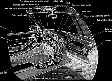
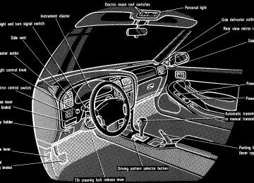
Instrument panel overview
3
Instrument cluster overview
Indicator symbols on the instrument panel
Brake system warning light*1
Seat belt reminder light*1
Discharge warning light*1
Malfunction indicator lamp*1
Low fuel level warning light*1
Low oil pressure warning light*1
Anit-lock brake system warning light*1
Open door warning light*1
Rear light failure warning light*1
SRS airbag warning light*1
Turn signal indicator lights
Headlight high beam indicator light
Overdrive-of f indicator light
“PWR” mode indicator light
Cruise control indicator light*2
Automatic transmission indicator lights
*1: For details, see “Service reminder indicators and warn-
ing buzzers” in Chapter 1-5.
*2: If this light flashes, see “Cruise control” in Chapter 1-6.
6
Part 1
OPERATION OF INSTRUMENTS AND CONTROLS—Keys
Chapter 1-2
Keys and Doors(cid:1) Keys (cid:1) Side doors (cid:1) Power windows (cid:1) Trunk lid (cid:1) Back door (cid:1) Hood (cid:1) Fuel tank cap (cid:1) Electric moon roof
The master key works in every lock. The subkey will not work in the trunk and glovebox. To protect things locked in the trunk or glvebox when you have your vehicle parked, leave the subkey with the atten- dant. Since the side doors, back door and trunk lid can be locked without a key, you should always carry a spare master key in case you accidentally lock your keys inside the vehicle.
Keep the key number plate in a safe place such as your wallet, not in the vehicle. If you should lose your keys or if you need additional keys, duplicates can be made by a Toyota dealer using the key number. You should also put a copy of the key number with your important papers.
Side doors
LOCKING WITH KEY Turn the key towards the front of the vehicle to lock and towards the back to unlock. Vehicles with power door lock sys- tem—All the side doors and back door lock and unlock simultaneously with either front door. In the driver’s door lock, turning the key once will unlock the driver’s door and twice in succession will unlock all the side doors and back door simultaneously. On some models, the door keyhole light will come on to help you locate the key- hole if you pull up and release the door handle when inserting the key into the driver’s door keyhole in the dark.
LOCKING WITH INSIDE LOCK KNOB Turn the lock knob forward to lock and backward to unlock the door. Closing the door with the lock knob in the lock position will also lock the door. Be careful not to lock your keys in the vehicle. Vehicles with power door lock system— The door cannot be locked if you leave the key in the ignition switch.
LOCKING WITH POWER DOOR LOCK SWITCH To lock all the side doors and back door simultaneously, push the power door lock switch on the LOCK side. Pushing on the UNLOCK side will un- lock them.
Power windows
CAUTION
Before driving, be sure that the doors are closed and locked, espe- cially when small children are in the vehicle. Along with the proper use of seat belts, locking the doors helps prevent the driver and passengers from being thrown out from the ve- hicle during an accident. It also helps prevent the doors from being opened unintentionally.
LOCKING WITH REAR DOOR CHILD- PROTECTORS Turn the lock knob to the “LOCK” position as shown on the label. This feature allows you to lock a rear door so it can be opened from the outside only, not from inside. We recommend using this feature whenever small children are in the vehicle.
The windows can be operated with the switch on each side door. The power windows work when the igni- tion switch is in the “ON” position. Howev- er, if both front doors are closed, they work for 60 seconds even after the ignition switch is turned off. They stop working when either front door is opened. OPERATING THE DRIVER’S WINDOW Use the switch on the driver’s door. Normal operation: The window moves as long as you hold the switch. To open: Lightly push down the switch. To close: Pull up the switch.
OPERATING THE PASSENGERS’ WIN- DOWS Use the switch on each passenger’s door or the switches on the driver’s door that control each passenger’s window. The windows move as long as you hold the switch. To open: Push down the switch. To close: Pull up the switch. If you push in the window lock button on the driver’s door, the passengers’ win- dows cannot be operated.
! CAUTION
To avoid serious personal injury, you must do the following. (cid:1) Always make sure the head, hands and other parts of the body of all oc- cupants are kept completely inside the vehicle before you close the power windows. If someone’s neck, head or hands gets caught in a clos- ing window, it could result in a seri- ous injury. When anyone closes the power windows, be sure that they operate the windows safely.
(cid:1) When small children are in the ve- hicle, never let them use the power window switches without supervi- sion. Use the window lock button to prevent them from making unex- pected use of the switches.
Automatic operation (to open only): Push the switch completely down and then release it. The window will fully open. To stop the window partway, lightly pull the switch up and then release it.
10
Trunk lid (sedan and coupe)—
—Lock release lever
(cid:1) Never leave small children alone in the vehicle, especially with the igni- tion key still inserted. They could use the power window switches and get trapped in a window. Unat- tended children can become in- volved in serious accidents.
To open the trunk lid from the driver’s seat, pull up on the lock release lever.
To open the trunk lid from the outside, insert the master key and turn it clock- wise. See “Luggage stowage precautions” in Part 2 for precautions to observe in load- ing luggage. To close the trunk lid, lower it and press down on it. After closing the trunk lid, try pulling it up to make sure it is securely closed.
CAUTION
Keep the trunk lid closed while driv- ing. This not only keeps the luggage from being thrown out but also pre- vents exhaust gases from entering the vehicle.
11
—Luggage security system
Back door (wagon)—
This system deactivates the lock re- lease lever so that things locked in the trunk can be protected. 1. Push down the security lock levers to lock the rear seatbacks. After locking the rear seatbacks, try folding them down to make sure they are securely locked—otherwise, someone could get into the trunk by folding down a rear seat.
2. After closing the trunk lid, insert the master key and turn it counterclock- wise to deactivate the lock release lev- er. After closing the trunk lid, try pulling it up to make sure it is securely locked.
12
FROM OUTSIDE To open the back door, insert the key and turn it clockwise to unlock. Then pull the handle and raise the door. To close the door, lower it and press down on it. After closing the back door, try pull- ing it up to make sure it is securely closed. FROM INSIDE (vehicles with third seat) Turn the lock knob rightward to lock and leftward to unlock the back door. To open the door, pull the handle and push the door outward. For closing, hold the lever and lower the door. After closing the back door, try push- ing it outward to make sure it is securely closed. See “Luggage stowage precautions” in Part 2 for precautions to observe in load- ing luggage. Closing the back door with the lock knob set in the lock position will also lock the back door. Be careful not to lock your keys in the vehicle.
—Power back door lock
Vehicles with power door lock sys- tem—To lock the back door, push the power door lock switch on the LOCK side. Pushing on the UNLOCK side will unlock it. At this time, all the side doors are oper- ated simultaneously (See “Side doors”.). You can, of course, lock and unlock the back door manually.
Vehicles without power door lock sys- tem—To lock the back door, push the switch on the “LOCK” side. To unlock the back door, push the switch on the “UNLOCK” side. You can, of course, lock and unlock the back door manually.
13
—Back door child protector (with third seat)
Hood
CAUTION
(cid:1) Before driving, be sure that the doors are closed and locked. Along with the proper use of seat belts, locking the back door helps prevent the passengers from be- ing thrown out from the vehicle during an accident. It also helps prevent the back door from being opened unintentionally.
(cid:1) Keep the back door closed while driving. This not only keeps the luggage from being thrown out but also prevents exhaust gases from entering the vehicle.
To open the hood, pull the hood lock release lever under the dash. The hood will spring up slightly. In front of the vehicle, press up on the auxiliary catch lever and lift the hood. Before closing the hood, check to see that you have not forgotten any tools, rags, etc. Then lower the hood and make sure it locks into place. If necessary, press down gently on the front edge to lock it.
Move the lock lever to the “LOCK” position as shown on the label. This feature allows you to lock a back door so it can be opened from the outside only, not from inside. We recommend using this feature whenever small children are in the vehicle.
14
Fuel tank cap
1. To open the fuel filler door, pull the lever up.
CAUTION
(cid:1) Do not smoke, cause sparks or al- low open flames when refueling. The fumes are flammable.
(cid:1) When opening the cap, do not re- move the cap quickly. In hot weather, fuel under pressure could cause injury by spraying out of the filler neck if the cap is sud- denly removed.
2. To remove the fuel tank cap, turn the cap slowly counterclockwise, then pause slightly before removing it. Af- ter removing the cap, hang it on the cap hanger. It is not unusual to hear a slight swoosh when the cap is opened. When installing, turn the cap clockwise till you hear a click. 5S-FE engined vehicles with automatic transmission— If the cap is not tightened securely, the malfunction indicator lamp comes on. Make sure the cap is tightened securely. The indicator lamp goes off after driving several times. If the indicator lamp does not go off, contact your Toyota dealer as soon as possible.
15
Electric moon roof
CAUTION
(cid:1) Make sure the cap is tightened se- curely to prevent fuel spillage in case of an accident.
(cid:1) Use only a genuine Toyota fuel tank cap for replacement. It has a built-in check valve to reduce fuel tank vacuum.
To open the moon roof, push the switch on the “SLIDE” side. Pushing on the opposite side will close it. To tilt up the rear end of the moon roof, push the switch on the “UP” side. Pushing on the opposite side will lower it. The moon roof works when the ignition switch is in the “ON” position. However, if both front doors are closed, it works for 60
seconds even after the ignition switch is turned off. It stops working when either front door is opened. The moon roof will move while the switch is being pushed and stop when released. However, as a precaution when closing, it stops at the three-quarters closed posi- tion before fully closing. Therefore, re- lease the switch and then push it again to close it completely. You may open the moon roof to any de- sired position. The sun shade can be opened or closed manually. However, if you open the moon roof, the sun shade will be opened togeth- er with the moon roof.16
CAUTION
To avoid serious personal injury, you must do the following. (cid:1) While the vehicle is moving, al- ways keep the head, hands and other parts of the body of all occu- pants away from the roof opening. Otherwise, you could be seriously injured if the vehicle stops sud- denly or if the vehicle is involved in an accident.
(cid:1) Always make sure nobody places his/her head, hands and other parts of the body in the roof open- ing before you close the roof. If someone’s neck, head or hands gets caught in the closing roof, it could result in a serious injury. When anyone closes the roof, first make sure it is safe to do so.
(cid:1) Never leave small children alone in the vehicle, especially with the ignition key still inserted. They could use the moon roof switches and get trapped in the roof open- ing. Unattended children can be- come involved in serious acci- dents.
(cid:1) Never sit on top of the vehicle
around the roof opening.
17
18
Part 1
OPERATION OF INSTRUMENTS AND CONTROLS—Seats While the vehicle is being driven, all ve- hicle occupants should have the seatback upright, sit well back in the seat and prop- erly wear the seat belts provided.
Front seats— —Seat adjustment precautions
Adjust the driver’s seat so that the foot pedals, steering wheel and instrument panel controls are within easy reach of the driver.
CAUTION
CAUTION
(cid:1) Do not drive with the vehicle occu- pants not properly seated, such as sitting on top of a folded-down seatback, or luggage compartment. Persons not proper- ly seated and restrained by seat belts can be severely injured in the event of emergency braking or a collision.
the
in
(cid:1) During driving, do not let passen- gers stand up or move around be- tween seats. Balance can be un- steady and severe injuries can oc- cur in the event of emergency brak- ing or a collision.
Chapter 1-3
Seats, Seat belts, Steering wheel and Mirrors(cid:1) Seats (cid:1) Front seats (cid:1) Rear seats (cid:1) Head restraints (cid:1) Seat belts (cid:1) SRS airbags (cid:1) Child restraint (cid:1) Tilt steering wheel (cid:1) Outside rear view mirrors (cid:1) Anti-glare inside rear view
mirror
(cid:1) Vanity mirrors
(cid:1) Adjustments should not be made while the vehicle is moving, as the seat may unexpectedly move and cause the driver to lose control of the vehicle.
(cid:1) When adjusting the seat, be care- ful not to hit the seat against a pas- senger or luggage.
(cid:1) After adjusting the seat position, try sliding it forward and backward to make sure it is locked in posi- tion.
(cid:1) After adjusting the seatback, exert body pressure to make sure it is locked in position.
(cid:1) Do not put objects under the seats as they may interfere with the seat- lock mechanism or unexpectedly push up the seat position adjust- ing lever; the seat may suddenly move, causing the driver to lose control of the vehicle.
(cid:1) While adjusting the seat, do not put your hands under the seat or near the moving parts. You may jam your hands or fingers.
19
—Adjusting front seats (manual seat)
20
ADJUSTING DRIVER’S SEAT CUSH- ION ANGLE Turn the knob either way. ADJUSTING DRIVER’S SEAT LUM- BAR SUPPORT Pull the lever forward and release. Repeat this until you have a comfortable support.
ADJUSTING SEAT POSITION Pull the lock release lever up. Then slide the seat to the desired position with slight body pressure and release the lever. ADJUSTING SEATBACK ANGLE Lean forward and pull the lock release lever. Then lean back to the desired angle and release the lever.
CAUTION
To reduce the risk of sliding under the lap belt during a collision, avoid reclining the seatback any more than needed. The seat belts provide maximum protection when the driv- er and the passenger are sitting up straight and well back in the seats. If you are reclined, the lap belt may slide past your hips and apply re- straint forces directly to the abdo- men. Therefore, in the event of a frontal collision, the risk of personal injury may increase with increasing recline of the seatback.
—Adjusting front seats (power seat—type A)
ADJUSTING SEAT POSITION Move the control switch in the desired direction. Releasing the switch will stop the seat at that position. Do not place anything under the seat. It might interfere with the seat movement. ADJUSTING SEATBACK ANGLE Lean forward and pull the lock release lever. Then lean back to the desired angle and release the lever.
ADJUSTING DRIVER’S SEAT CUSH- ION ANGLE Move the control switch in the desired direction. Releasing the switch will stop the seat at that position. ADJUSTING DRIVER’S SEAT LUM- BAR SUPPORT Pull the lever forward and release. Repeat this until you have a comfortable support.
CAUTION
To reduce the risk of sliding under the lap belt during a collision, avoid reclining the seatback any more than needed. The seat belts provide maximum protection when the driv- er and the passenger are sitting up straight and well back in the seats. If you are reclined, the lap belt may slide past your hips and apply re- straint forces directly to the abdo- men. Therefore, in the event of a frontal collision, the risk of person- al injury may increase with increas- ing recline of the seatback.
21
—Adjusting front seats (power seat—type B)
22
ADJUSTING DRIVER’S SEAT CUSH- ION ANGLE Move the control switch in the desired direction. Releasing the switch will stop the seat at that position. ADJUSTING DRIVER’S SEAT LUM- BAR SUPPORT Pull the lever forward and release. Repeat this until you have a comfortable support.
ADJUSTING SEAT POSITION Move the control switch in the desired direction. Releasing the switch will stop the seat at that position. Do not place anything under the seat. It might interfere with the seat movement. ADJUSTING SEATBACK ANGLE Move the control switch in the desired direction. Releasing the switch will stop the seat- back at that position.
CAUTION
To reduce the risk of sliding under the lap belt during a collision, avoid reclining the seatback any more than needed. The seat belts provide maximum protection when the driv- er and the passenger are sitting up straight and well back in the seats. If you are reclined, the lap belt may slide past your hips and apply re- straint forces directly to the abdo- men. Therefore, in the event of a frontal collision, the risk of personal injury may increase with increasing recline of the seatback.
—Adjusting front seats (power seat—type C)
—Moving passenger’s seat for rear seat entry (coupe)
ADJUSTING SEAT POSITION Move the control switch in the desired direction. Releasing the switch will stop the seat at that position. Do not place anything under the seat. It might interfere with the seat movement. ADJUSTING SEATBACK ANGLE Move the control switch in the desired direction. Releasing the switch will stop the seat- back at that position.
CAUTION
To reduce the risk of sliding under the lap belt during a collision, avoid reclining the seatback any more than needed. The seat belts provide maximum protection when the driv- er and the passenger are sitting up straight and well back in the seats. If you are reclined, the lap belt may slide past your hips and apply re- straint forces directly to the abdo- men. Therefore, in the event of a frontal collision, the risk of personal injury may increase with increasing recline of the seatback.
For easy access to the rear seat, do this. 1. Lift the seatback lock release lever or press the release pedal. The seat will slide forward slightly. 2. Move the seat to the front-most posi- tion.
23
Rear seats— —Fold-down rear seat (sedan and coupe)
Unlock the seatback, and fold it down. This will enlarge the trunk room as far as the front seatbacks. See “Luggage stow- age precautions” in Part 2 for precautions to observe in loading luggage. If desired, each seatback may be folded separately.
CAUTION
When returning the seatback to the upright position: (cid:1) Make sure the seat belts are not twisted or caught in the seatback and are arranged in their proper position for ready use.
(cid:1) Make sure the seatback is secure- ly locked by pushing forward and rearward on the top of the seat- back.
Before entry, push the seat belt hanger down as far as it will go if it is in the raised position. After passengers are in, lift up the seat- back and return the seat until it locks.
CAUTION
(cid:1) After putting back the seat, try pushing the seat forward and rear- ward to make sure that it is se- cured in place.
(cid:1) Never allow anyone to rest their foot on the release pedal while the vehicle is moving.
24
—Fold-down rear seat (wagon)
BEFORE FOLDING REAR SEAT Stow the rear seat belts facing the di- rection shown in the illustration. This prevents them from falling out when you fold the seatback.
NOTICE
The seat belts must be stowed before you fold the seatback.
FOLDING REAR SEAT 1. Swing the bottom cushion up by pulling the lock release strap. It is hinged at the front edge, so just lift it up. If desired, each bottom cushion may be lifted separately.
CAUTION
When returning the bottom cushion to its original position: (cid:1) Make sure the seat belts are not twisted or caught under the bot- tom cushion and are arranged in their proper position for ready use.
(cid:1) Make sure the bottom cushion is securely locked by trying to pull up the edge of the cushion near the lock release straps.
25
3. After folding the seatback down, hook the strap to the tab on the reverse side of the seatback.
4. Store the head restraint using the head restraint retaining holes in the bottom cushion.
CAUTION
When returning the seatback to the upright position: (cid:1) Make sure the seat belts are not twisted or caught in the seatback and are arranged in their proper position for ready use.
(cid:1) Make sure the seatback is secure- ly locked by pushing forward and rearward on the top of the seat- back.
2. Remove the head restraint, unlock the seatback and fold it down while pushing the bottom cushion forward. This will enlarge the luggage compart- ment as far as the raised bottom cushion. See “Luggage stowage precautions” in Part 2 for precautions to observe in load- ing luggage. If desired, each seat may be folded sepa- rately.
26
—Fold-down third seat (wagon)
—Take-down third seat (wagon)
1. Swing the seatback up with the handle.
2. Turn the bottom cushion over with the handle.
CAUTION
(cid:1) Take care not to get your hands or
fingers caught.
(cid:1) Make sure the seatback is securely locked by pushing forward and rearward on the top of the seat- back.
(cid:1) When using the third seat, for your safety make sure the rear seatback is also upright and securely locked.
BEFORE TAKING DOWN THIRD SEAT Stow the third seat belts facing the di- rection shown in the illustration. This prevents them from falling out when you fold the seatback.
NOTICE
The seat belts must be stowed before you fold the seatback.
27
Head restraints (vertically adjustable type)
TAKING DOWN THIRD SEAT 1. Turn the bottom cushion over.
2. Release the lock release lever and fold down the seatback.
CAUTION
Take care not to get your hands or fingers caught.
To raise the head restraint, pull it up. To lower it, press the lock release but- ton and push the head restraint down. The head restraint is most effective when it is close to your head. Therefore, using a cushion on the seatback is not recom- mended.
CAUTION
(cid:1) Adjust the top of the head restraint so that it is closest to the top of your ears.
(cid:1) After adjusting the head restraint, make sure it is locked in position. (cid:1) Do not drive with the head re-
straints removed.
28
Head restraints (vertically and rotationally adjustable type)
CAUTION
(cid:1) Adjust the top of the head restraint so that it is closest to the top of your ears.
(cid:1) After adjusting the head restraint, make sure it is locked in position. (cid:1) Do not drive with the head re-
straints removed.
To raise the head restraint, pull it up. To lower it, press the lock release but- ton and push the head restraint down. To move the head restraint forward, pull on the top. Pulling the top of the head restraint as far as it can go will return it to the upright posi- tion. The head restraint is most effective when it is close to your head. Therefore, using a cushion on the seatback is not recom- mended.
29
Seat belts— —Seat belt precautions Toyota recommends that the driver and passengers in the vehicle be properly re- strained at all times with the seat belts pro- vided. Failure to do so could increase the chance of injury and/or the severity of injury in accidents. Baby or small child. Use a child restraint system which fits your vehicle. See “Child restraint” for details. Child. If a child is too large for a child re- straint system, the child should sit in the rear seat and must be restrained using the vehicle’s seat belt. According to accident statistics, the child is safer when properly restrained in the rear seat than in the front seat. Do not allow the child to stand up or kneel on either rear or front seats. If the shoulder belt falls across the child’s neck or face, move the child to the center position and use the center lap belt. Pregnant woman. Toyota recommends the use of a seat belt. Ask your doctor for specific recommendations. The lap belt should be worn securely and as low as pos- sible over the hips and not on the waist. Injured person. Toyota recommends the use of a seat belt. Depending on the injury, however, first check with your doctor.
30
CAUTION
Persons should ride in their seats properly wearing their seat belts whenever the vehicle is moving. Otherwise, they are much more like- ly to suffer serious bodily injury in the event of sudden braking or a col- lision.
(cid:1) Keep the belts clean and dry. If they need cleaning, use a mild soap solution or lukewarm water. Never use bleach, dye, or abrasive clean- ers—they may severely weaken the belts.
(cid:1) Replace the belt assembly (includ- ing bolts) if it has been used in a severe impact. The entire assem- bly should be replaced even if damage is not obvious.
When using the seat belts, observe the following: (cid:1) Use the belt for only one person at a time. Do not use a single belt for two or more people—even chil- dren.
(cid:1) Avoid reclining the seatbacks too much. The seat belts provide maxi- mum protection when the seat-