- 2006 Subaru Legacy Owners Manuals
- Subaru Legacy Owners Manuals
- 2004 Subaru Legacy Owners Manuals
- Subaru Legacy Owners Manuals
- 2008 Subaru Legacy Owners Manuals
- Subaru Legacy Owners Manuals
- 2005 Subaru Legacy Owners Manuals
- Subaru Legacy Owners Manuals
- 2007 Subaru Legacy Owners Manuals
- Subaru Legacy Owners Manuals
- 2000 Subaru Legacy Owners Manuals
- Subaru Legacy Owners Manuals
- 2003 Subaru Legacy Owners Manuals
- Subaru Legacy Owners Manuals
- 2012 Subaru Legacy Owners Manuals
- Subaru Legacy Owners Manuals
- 2001 Subaru Legacy Owners Manuals
- Subaru Legacy Owners Manuals
- 2010 Subaru Legacy Owners Manuals
- Subaru Legacy Owners Manuals
- 2011 Subaru Legacy Owners Manuals
- Subaru Legacy Owners Manuals
- 2009 Subaru Legacy Owners Manuals
- Subaru Legacy Owners Manuals
- 2002 Subaru Legacy Owners Manuals
- Subaru Legacy Owners Manuals
- Download PDF Manual
-
UB8048BB
1) T-30 torx® head screw 2) Lower clamp 1. Loosen and remove the T-30 torx® head screw from the top of each crossbar end support. 2. Rotate the lower clamp on the bottom of each end support downward approximately 90°.
– CONTINUED – 8-21
Driving tips
3. Carefully raise the crossbar from roof rails.
UB8051BA
8-22
(cid:86) To install the crossbar Front crossbar: Front crossbar has 100 LBS Load Label on left-hand side.
UB8048BB
1) T-30 torx® head screw 2) Lower clamp 1. Before placing the crossbar on the roof rails, make sure that the T-30 torx® head screw is removed from the top of each crossbar end support. 2. Rotate the lower clamp on the bottom of each end support downward approximately 90°.
6 in (150mm)
UB8049BB
1) 100 LBS load label 2) Front arrow label 3. With the front direction arrow label on the top right side of the crossbar pointing toward the front of the ve- hicle, carefully place the crossbar across the top of the vehicle so that the crossbar end supports rest on the top of the roof rails approximately 6 inches (150 mm) rearward from the seam (joint) between the front roof rail support and the roof rail. 4. Rotate (raise) the lower clamp up to the bottom of the roof rail and loosely tighten the T-30 torx® head screw with the torx® wrench provided, through the top of the end support and into the threaded insert in the
Driving tips
lower clamp on each end of the crossbar. NOTE It may be necessary to squeeze the lower clamp and the end support together to compress the pads and gain a better alignment of the pieces while trying to start the screw. Use care not to crossthread the screw in the insert. 5. Adjust the alignment of the crossbar on the roof rails, and if available, use a T-30 torx® bit and torque wrench and tighten the T-30 torx® head screws to 30
to 35 lbf·in (3.4 to 4.0 N·m, 0.35 to 0.41 kgf·m) of torque (or tighten securely with the torx® wrench pro- vided).– CONTINUED – 8-23
bars are removed. Luggage on the roof will be thrown forward or backward in sudden stops or rapid accelerations, resulting in a dangerous road hazard.
NOTE Before each use of the roof crossbar, make sure the four T-30 crossbar clamp screws have been checked, and retightened if necessary to 35 lbf·in (4.0 N·m, 0.41 kgf·m), as outlined in Step #5 above.
Driving tips
Rear crossbar:
6 in (150 mm)
UB8050BB
1) T-30 torx® head screw 2) Front arrow label Install the rear crossbar in the same manner as the front crossbar. NOTE The rear crossbar should be positioned 6 inches (150 mm) forward of the rear seam (joint) between the rear roof rail support and the roof rail.
Do not carry cargo on the roof when the cross-
8-24
Trailer hitch (if equipped)
tributing hitch.
Driving tips
(cid:121) Never exceed the maximum weight specified for the trailer hitch. Exceeding the maximum weight could cause an accident resulting in se- rious personal injuries. Permissible trailer weight changes depending on the situation. Re- fer to the next section “Trailer towing” for pos- sible recommendations and limitations. (cid:121) Trailer brakes are required when the towing load exceeds 1,000 lbs (453 kg). Be sure your trailer has safety chains and that each chain will hold the trailer’s maximum gross weight. Towing trailers without safety chains could cre- ate a traffic safety hazard if the trailer separates from the hitch due to coupling damage or hitch ball damage. (cid:121) Be sure to check the hitch pin and safety pin for positive locking placement before towing a trailer. If the ball mount comes off the hitch re- ceiver, the trailer could get loose and create a traffic safety hazard. (cid:121) Use only the ball mount supplied with this hitch. Use the hitch only as a weight carrying hitch. Do not use with any type of weight dis-
The trailer hitch is designed to tow a Class 1 rated load. A maximum of 2,400 lbs (1,087 kg) gross trailer weight and a maximum of 200 lbs (90 kg) gross tongue weight are permissible for the trailer hitch. When you tow a trailer, follow the instructions in the next section “Trailer towing”.
(cid:132) Connecting a trailer 1. Remove the receiver cover from the hitch receiver tube. Then insert the ball mount into the hitch receiver tube.
UB8018BA
– CONTINUED – 8-25
Driving tips
2. Insert the hitch pin into the hole on the hitch receiv- er tube so that the pin passes through the ball mount.
3. Insert the safety pin into the hitch pin securely. 4. Pull the ball mount to make sure it does not come off the hitch receiver.
HS8012BA
8-26
UB8020BB
1) Hitch ball installation point 2) Hooks for safety chains 5. Use only a hitch ball that is appropriate for the ball mount and your trailer. The hitch ball must be securely installed on the ball mount. 6. Connect your trailer to the hitch ball. 7. Connect the trailer and the hitch with safety chains that will hold the trailer’s maximum gross weight. The chains should cross under the trailer tongue to prevent the tongue from dropping onto the ground in case it should disconnect from the hitch ball. Allow sufficient slack in the chains taking tight-turn situations into ac- count; however, be careful not to let them drag on the
ground.
Driving tips
UG8034BA
Do not connect safety chains to part of the ve- hicle other than the safety chain hooks.
HS8015BA
Hitch harness connector 8. Connect the hitch wire harness’s black four-pin wire connector to the towing trailer’s wire harness. 9. Confirm proper function of the hitch wire harness by individually activating the brake, right turn signal, left turn signal, stop, and parking lights on the trailer. NOTE Always disconnect the trailer wire harness before launching or retrieving a watercraft.
(cid:132) When you do not tow a trailer (cid:121) Remove the ball mount from the hitch receiver tube – CONTINUED – 8-27
Driving tips
and insert the receiver cover onto the hitch receiver tube. (cid:121) Place the dust cap over the four-pin connector of the hitch wire harness to protect against possible damage. (cid:121) Occasionally lubricate terminals of the four-pin con- nector using the terminal grease.
8-28
Trailer towing Your car is designed and intended to be used primarily as a passenger-carrying vehicle. Towing a trailer puts additional loads on your car’s engine, drivetrain, brakes, tires and suspension and has an adverse ef- fect on fuel economy. If you do decide to tow a trailer, your safety and satis- faction depend upon proper use of correct equipment and cautious operation of your vehicle. Seek the ad- vice of your SUBARU dealer to assist you in purchas- ing a hitch and other necessary towing equipment ap- propriate for your vehicle. In addition, be sure to follow the instructions on correct installation and use provid- ed by the trailer and other towing equipment manufac- turers. SUBARU assumes no responsibility for injuries or ve- hicle damage that result from trailer towing equipment, or from any errors or omissions in the instructions ac- companying such equipment or for your failure to fol- low the proper instructions.
(cid:132) Warranties and maintenance SUBARU warranties do not apply to vehicle damage or malfunction caused by trailer towing. If you use your vehicle to tow a trailer, more frequent maintenance will be required due to the additional load. (Refer to “Main-
tenance schedule under severe driving conditions” in the “Warranty and Maintenance Booklet”.) Under no circumstances should a trailer be towed with a new vehicle or a vehicle with any new powertrain component (engine, transmission, differential, wheel bearings, etc.) for the first 1,000 miles (1,600 km) of driving.
(cid:132) Maximum load limits
Never exceed the maximum load limits ex- plained below. Exceeding the maximum load limits could cause personal injury and/or vehi- cle damage.
(cid:121) Adequate size trailer brakes are required when the trailer and its cargo exceed 1,000 lbs (453 kg) total weight. (cid:121) Before towing a trailer, check the trailer total weight, GVW, GAWs and tongue load. Make sure the load and its distribution in your vehicle
Driving tips
and trailer are acceptable.
(cid:84) Total trailer weight
HS8016AA
Total trailer weight The total trailer weight (trailer weight plus its cargo load) must never exceed the maximum weight shown below.
– CONTINUED – 8-29
Driving tips
OUTBACK Wagon
Model
Conditions
MT models When towing a trailer with-
out brakes.
When towing a trailer with brakes.
AT models When towing a trailer with-
out brakes.
When towing a trailer with brakes.
When towing a trailer on a long uphill grade continu- ously for over 5 miles (8 km) with an outside temperature of 104°F (40°C) or above.
Maximum total trailer
weight
1,000 lbs (453 kg)
2,400 lbs (1,087 kg)
1,000 lbs (453 kg)
2,400 lbs (1,087 kg)
1,200 lbs (543 kg)
Others
Model
Conditions
MT models When towing a trailer with-
out brakes.
When towing a trailer with brakes.
AT models When towing a trailer with-
out brakes.
When towing a trailer with brakes.
When towing a trailer on a long uphill grade continu- ously for over 5 miles (8 km) with an outside temperature of 104°F (40°C) or above.
Maximum total trailer
weight
1,000 lbs (453 kg)
2,000 lbs (906 kg)
1,000 lbs (453 kg)
2,000 lbs (906 kg)
1,000 lbs (453 kg)
8-30
(cid:84) Gross Vehicle Weight (GVW) and Gross Vehicle
Weight Rating (GVWR)
the driver’s door of your vehicle.
Driving tips
OM-U2782
Certification label
UBF019BA
Gross Vehicle Weight The Gross Vehicle Weight (GVW) must never exceed the Gross Vehicle Weight Rating (GVWR). Gross Vehicle Weight (GVW) is the combined total of the weight of the vehicle, driver, passengers, luggage, trailer hitch, trailer tongue load and any other optional equipment installed on your vehicle. Therefore, the GVW changes depending on the situation. Determine the GVW each time before going on a trip by putting your vehicle and trailer on a vehicle scale. GVWR is shown on the certification label located on
– CONTINUED – 8-31
Driving tips
(cid:84) Gross Axle Weight (GAW) and Gross Axle
Weight Rating (GAWR)
OM-U2784
Gross Axle Weight The total weight applied to each axle (GAW) must nev- er exceed the Gross Axle Weight Rating (GAWR). The front and rear GAWs can be adjusted by relocating passengers and luggage inside the vehicle. The front and rear GAWR are also shown on the certification la- bel.
UBF019BA
Certification label To check both GVWR and GAWR and to confirm that the total weight and weight distribution are within safe driving limits, you should have your vehicle and trailer weighed at a commercial weighing station. Be sure that all cargo is firmly secured to prevent a change in weight distribution while driving.
8-32
(cid:84) Tongue load
Driving tips
Ensure that the trailer tongue load is from 8 to 11 per- cent of the total trailer weight and does not exceed the maximum value of 200 lbs (90 kg).
Tongue load
HS8019AA
If the trailer is loaded with more weight in the back of trailer’s axle than in the front, the load is taken off the rear axle of the towing vehicle. This may cause the rear wheels to skid, espe- cially during braking or when vehicle speed is reduced during cornering, resulting in over- steer, spin out and/or jackknifing.
OM-U2786
1) Jack 2) Bathroom scale The tongue load can be weighed with a bathroom scale as shown in the illustration below. When weigh- ing the tongue load, be sure to position the towing cou- pler at the height at which it would be during actual towing, using a jack as shown.
– CONTINUED – 8-33
Driving tips
60%
40%
50% 50%
HS8021BB
F: Front The tongue load can be adjusted by proper distribution of the load in the trailer. Never load the trailer with more weight in the back than in the front; approximate- ly 60 percent of the trailer load should be in the front and approximately 40 percent in the rear. Also, distrib- ute the load as evenly as possible on both the left and right sides. Be sure that all cargo is firmly secured to prevent a change in weight distribution while driving.
8-34
(cid:132) Trailer hitches
Never drill the frame or under-body of your ve- hicle to install a commercial trailer hitch. If you do, dangerous exhaust gas, water or mud may enter the passenger compartment through the drilled hole. Exhaust gas contains carbon mon- oxide, a colorless and odorless gas which is dangerous, or even lethal, if inhaled. Also, drill- ing the frame or under-body of your vehicle could cause deterioration of strength of your vehicle and cause corrosion around the drilled hole.
(cid:121) Do not modify the vehicle exhaust system, brake system, or other systems when installing a hitch or other trailer towing equipment. (cid:121) Do not use axle-mounted hitches as they can cause damage to the axle housing, wheel bear- ings, wheels or tires.
Choose a proper hitch for your vehicle and trailer.
(cid:84) OUTBACK wagon The use of a genuine SUBARU trailer hitch is recom- mended. A genuine SUBARU hitch is available from your SUBARU dealer. If use of a non-genuine hitch is unavoidable, be sure the hitch is suited to your vehicle and trailer. Consult with a professional hitch supplier to assist you in choosing an appropriate hitch for your vehicle. Be sure to follow all of the hitch manufacturer’s instructions for installation and use. Never use a hitch that mounts only to the rear bumper. The bumper is not designed to handle that type of load. For all types of hitches, regularly check that the hitch mounting bolts and nuts are tight. (cid:84) All vehicles except OUTBACK wagon SUBARU does not offer accessory trailer hitches. Consult with a professional hitch supplier to assist you in choosing an appropriate hitch for your vehicle. Be sure to follow all of the hitch manufacturer’s instruc- tions for installation and use. Never use a hitch that mounts only to the rear bumper. The bumper is not designed to handle that type of load. Regularly check that the hitch mounting bolts and nuts are tight.
Driving tips
(cid:132) Connecting a trailer (cid:84) Trailer brakes
(cid:121) Adequate size trailer brakes are required when the trailer and its cargo exceed 1,000 lbs (453 kg) total weight. (cid:121) Do not directly connect your trailer’s hydrau- lic brake system to the hydraulic brake system in your vehicle. Direct connection would cause the vehicle’s brake performance to deteriorate and could lead to an accident.
If your trailer’s total weight (trailer weight plus its cargo weight) exceeds 1,000 lbs (453 kg), the trailer is re- quired to be equipped with its own brake system. Elec- tric brakes or surge brakes are recommended, and must be installed properly. Check that your trailer’s brakes conform with Federal, state/province and/or other applicable regulations. Your SUBARU’s brake system is not designed to be tapped into the trailer’s hydraulic brake system. Please ask your SUBARU dealer and professional trailer supplier for more infor- mation about the trailer’s brake system.
– CONTINUED – 8-35
Driving tips
(cid:84) Trailer safety chains
(cid:84) Side mirrors
Always use safety chains between your vehicle and the trailer. Towing trailer without safety chains could create a traffic safety hazard if the trailer separates from the hitch due to coupling damage or hitch ball damage.
In case the trailer hitch connector or hitch ball should break or become disconnected, the trailer could get loose and create a traffic safety hazard. For safety, always connect the towing vehicle and trailer with trailer safety chains. Pass the chains cross- ing each other under the trailer tongue to prevent the trailer from dropping onto the ground in case the trailer tongue should disconnect from the hitch ball. Allow sufficient slack in the chains taking tight-turn situations into account; however, be careful not to let them drag on the ground. For more information about the safety chain connec- tion, refer to the instructions for your hitch and trailer.
8-36
UB0085
After hitching a trailer to your vehicle, check that the standard side mirrors provide a good rearward field of view without significant blind spots. If significant blind spots occur with the vehicle’s standard side mirrors, use towing mirrors that conform with Federal, state/ province and/or other applicable regulations. (cid:84) Trailer lights
Direct splicing or other improper connection of trailer lights may damage your vehicle’s electri-
cal system and cause a malfunction of your ve- hicle’s lighting system.
Connection of trailer lights to your vehicle’s electrical system requires modifications to the vehicle’s lighting circuit to increase its capacity and accommodate wir- ing changes. To ensure the trailer lights are connected properly, please consult your SUBARU dealer. Check for proper operation of the turn signals, the brake lights and parking lights each time you hitch up. (cid:84) Tires
Never tow a trailer when the temporary spare tire is used. The temporary spare tire is not de- signed to sustain the towing load. Use of the temporary spare tire when towing can result in failure of the spare tire and/or less stability of the vehicle.
Make sure that all the tires on your vehicle are properly inflated. The recommended cold tire pressure under trailer tow- ing conditions is shown in chapter 12, “Specifications”
Driving tips
and in “GAS STATION REFERENCE” at the end of this manual. Adjust the rear tire pressure to the recom- mended pressure when the tires are cold. Normal pressure should be maintained in the front tires. Trailer tire condition, size, load rating and proper infla- tion pressure should be in accordance with the trailer manufacturer’s specifications. In the event your vehicle gets a flat tire when towing a trailer, ask a commercial road service to repair the flat tire. If you carry a regular size spare tire in your vehicle or trailer as a precaution against getting a flat tire, be sure that the spare tire is firmly secured.
(cid:132) Trailer towing tips
(cid:121) Never exceed 45 mph (72 km/h) when towing a trailer in hilly country on hot days. (cid:121) When towing a trailer, steering, stability, stopping distance and braking performance will be different from normal operation. For safety’s sake, you should employ extra caution when towing a trailer and you should never
– CONTINUED – 8-37
Driving tips
speed. You should also keep the following tips in mind:
(cid:84) Before starting out on a trip (cid:121) Check that the vehicle and vehicle-to-hitch mount- ing are in good condition. If any problems are appar- ent, do not tow the trailer. (cid:121) Check that the vehicle sits horizontally with the trail- er attached. If the vehicle is tipped sharply up at the front and down at the rear, check the total trailer weight, GVW, GAWs and tongue load again, then con- firm that the load and its distribution are acceptable. (cid:121) Check that the tire pressures are correct. (cid:121) Check that the vehicle and trailer are connected properly. Confirm that.
– the trailer tongue is connected properly to the hitch ball. – the trailer lights connector is connected properly and trailer’s brake lights illuminate when the vehi- cle’s brake pedal is pressed, and that the trailer’s turn signal lights flash when the vehicle’s turn signal lever is operated. – the safety chains are connected properly. – all cargo in the trailer is secured safety in position. – the side mirrors provide a good rearward field of view without a significant blind spot.
8-38
(cid:121) Sufficient time should be taken to learn the “feel” of the vehicle/trailer combination before starting out on a trip. In an area free of traffic, practice turning, stopping and backing up. (cid:84) Driving with a trailer (cid:121) You should allow for considerably more stopping distance when towing a trailer. Avoid sudden braking because it may result in skidding or jackknifing and loss of control. (cid:121) Avoid abrupt starts and sudden accelerations. If your vehicle has a manual transmission, always start out in first gear and release the clutch at moderate en- gine revolution. (cid:121) Avoid uneven steering, sharp turns and rapid lane changes. (cid:121) Slow down before turning. Make a longer than nor- mal turning radius because the trailer wheels will be closer than the vehicle wheels to the inside of the turn. In a tight turn, the trailer could hit your vehicle. (cid:121) Crosswinds will adversely affect the handling of your vehicle and trailer, causing sway. Crosswinds can be due to weather conditions or the passing of large trucks or buses. If swaying occurs, firmly grip the steering wheel and slow down immediately but gradu- ally. (cid:121) When passing other vehicles, considerable dis- tance is required because of the added weight and
length caused by attaching the trailer to your vehicle.
HS8023BB
1) Left turn 2) Right turn (cid:121) Backing up with a trailer is difficult and takes prac- tice. When backing up with a trailer, never accelerate or steer rapidly. When turning back, grip the bottom of the steering wheel with one hand and turn it to the left for a left turn, and turn it to the right for a right turn. (cid:121) If the ABS warning light illuminates while the vehicle is in motion, stop towing the trailer and have repairs performed immediately by the nearest SUBARU deal- er.
Driving tips
(cid:84) Driving on grades (cid:121) Before going down a steep hill, slow down and shift into lower gear (if necessary, use 1st gear) in order to utilize the engine braking effect and prevent overheat- ing of your vehicle’s brakes. Do not make sudden downshifts. (cid:121) When driving uphill in hot weather, the air condition- er may turn off automatically to protect the engine from overheating. (cid:121) When driving uphill in hot weather, pay attention to the water temperature gauge pointer (for all vehicles) and AT OIL TEMP warning light (for AT vehicles) since the engine and transmission are relatively prone to overheating under these conditions. If the water tem- perature gauge pointer approaches the OVERHEAT zone or the AT OIL TEMP warning light illuminates, immediately switch off the air conditioner and stop the vehicle at the nearest safe place. Refer to the “Engine overheating” section in chapter 9, and “Warning and indicator lights” section in chapter 3. (cid:121) If your vehicle has an automatic transmission, avoid using the accelerator pedal to stay stationary on an uphill slope instead of using the parking brake or foot brake. That may cause the transmission fluid to over- heat. Also, if your vehicle is equipped with an automat- ic transmission, avoid driving with the gear selector le- ver in “D” when towing a heavy trailer to prevent fluid – CONTINUED – 8-39
Driving tips
overheating. A lower gear should be used. (cid:84) Parking on a grade Always block the wheels under both vehicle and trailer when parking. Apply the parking brake firmly. You should not park on a hill or slope. But if parking on a hill or slope cannot be avoided, you should take the following steps: 1. Apply the brakes and hold the pedal down. 2. Have someone place wheel blocks under both the vehicle and trailer wheels. 3. When the wheel blocks are in place, release the regular brakes slowly until the blocks absorb the load. 4. Apply the regular brakes and then apply the park- ing brake; slowly release the regular brakes. 5. Shift into 1st or reverse gear (manual transmission) or “P” (automatic transmission) and shut off the en- gine.
8-40
In case of emergency
How to jump start .............................................
If steam is coming from the engine If no steam is coming from the engine
9-2
If you park your vehicle in an emergency .. 9-3
Temporary spare tire .................................... Flat tires ......................................................... 9-5
Jump starting ................................................ 9-15
9-16
Engine overheating ....................................... 9-19
9-19
9-19
Towing ........................................................... 9-20
Towing and tie-down hooks ............................ 9-21
Using a flat-bed truck ....................................... 9-27
Towing with all wheels on the ground ............ 9-28
Moonroof – if the moonroof cannot be closed ......................................................... 9-29
Maintenance tools ......................................... 9-31
9-32compartment .................................................. compartment ..................................................
Jack and jack handle ........................................
9-1
In case of emergency
In case of emergency
If you park your vehicle in an emer- gency
NOTE When the hazard warning flasher is on, the turn signals do not work.
UB8002BA
The hazard warning flasher should be used in day or night to warn other drivers when you have to park your vehicle under emergency conditions. Avoid stopping on the road. It is best to safely pull off the road if a problem occurs. The hazard warning flasher can be activated regard- less of the ignition switch position. Turn on the hazard warning by pushing the hazard warning flasher switch. Turn it off by pushing the switch again.
9-2
Temporary spare tire
Never tow a trailer when the temporary spare tire is used. The temporary spare tire is not de- signed to sustain the towing load. Use of the temporary spare tire when towing can result in failure of the spare tire and/or less stability of the vehicle and may lead to an accident.
In case of emergency
rect pressure is 60 psi (420 kPa, 4.2 kg/cm2). When using the temporary spare tire, note the follow- ing: (cid:121) Do not exceed 50 mph (80 km/h). (cid:121) Do not put a tire chain on the temporary spare tire. Because of the smaller tire size, a tire chain will not fit properly. (cid:121) Do not use two or more temporary spare tires at the same time. (cid:121) Do not drive over obstacles. This tire has a smaller diameter, so road clearance is reduced.
Never use any temporary spare tire other than the original. Using other sizes may result in se- vere mechanical damage to the drive train of your vehicle.
The temporary spare tire is smaller and lighter than a conventional tire and is designed for emergency use only. Remove the temporary spare tire and re-install the conventional tire as soon as possible because the spare tire is designed only for temporary use. Check the inflation pressure of the temporary spare tire periodically to keep the tire ready for use. The cor-
1) Tread wear indicator bar 2) Indicator location mark
UG0106
– CONTINUED – 9-3
In case of emergency
(cid:121) When the wear indicator appears on the tread, re- place the tire.
tivated. After re-installing the conventional tire, re- move the spare fuse from the FWD connector in order to reactivate all wheel drive.
UB8003BC
1) Spare fuse 2) FWD connector NOTE [Automatic transmission vehicle not equipped with VDC (Vehicle Dynamics Control) and not equipped with SPORTSHIFT] Before driving your vehicle with the temporary spare tire, put a spare fuse inside the FWD connector located in the en- gine compartment and confirm that the Front- wheel drive warning light comes on. The all wheel drive capability of the vehicle has now been deac-
9-4
Flat tires
(cid:121) Do not jack up the vehicle on an incline or a loose road surface. The jack can come out of the jacking point or sink into the ground and this can result in a severe accident. (cid:121) Use only the jack provided with your vehicle. The jack supplied with the vehicle is designed only for changing a tire. Never get under the ve- hicle while supporting the vehicle with this jack. (cid:121) Always turn the engine off before raising the flat tire off the ground using the jack. Never swing or push the vehicle supported with the jack. The jack can come out of the jacking point due to a jolt and this can result in a severe acci- dent. (cid:121) Do not use oil or grease on the wheel studs or nuts when the spare tire is installed. This could cause the nuts to become loose and lead to an accident.
If you have a flat tire while driving, never brake sud- denly; keep driving straight ahead while gradually re-
In case of emergency
ducing speed. Then slowly pull off the road to a safe place. 1. Park on a hard, level surface, whenever possible, then stop the engine. 2. Set the parking brake securely and shift a manual transmission vehicle in reverse or an automatic trans- mission vehicle in the “P” (Park) position. 3. Turn on the hazard warning flasher and have ev- eryone get out of the vehicle.
4. Put wheel blocks at the front and rear of the tire di- agonally opposite the flat tire.
HS9003BA
– CONTINUED – 9-5
2
In case of emergency
Sedan 1) Jack 2) Jack handle 3) Spare tire
9-6
UBF015CB
UB8004BD
Station wagon 1) Jack 2) Jack handle 3) Spare tire 5. Take out the spare tire, jack, and wheel nut wrench.
To remove the spare tire, proceed as follows:
In case of emergency
Sedan: Remove the floor cover from the trunk. Re- move the storage tray.
UB9003BA
Turn the attaching bolt counterclockwise, then take the spare tire out.
US0252
– CONTINUED – 9-7
In case of emergency
UB6008BA
US0252
Station wagon: Open the lid and hang the hook pro- vided on the underside of the lid on the rear edge of the roof to keep the lid open. Remove the storage tray.
Turn the attaching bolt counterclockwise, then take spare tire out. If the spare tire provided in your vehicle is a temporary spare tire, carefully read the section “Temporary spare tire” in this chapter and strictly follow the instructions.
9-8
In case of emergency
Sedan
UB9001BA
UB7008CA
Station wagon The jack is stored on the left side of the trunk or cargo area. To take out the jack: Remove the cover, turn the jackscrew counterclock- wise to loosen it, then remove the jack.
– CONTINUED – 9-9
In case of emergency
UB1169CA
UB9032BA
If the jackscrew is too tight to be loosened by hand, loosen it using a screwdriver or the jack handle. The jack handle is stored under the spare tire cover. NOTE Make sure the jack is well lubricated before using it.
6. (If your vehicle has wheel covers) Insert the wheel nut wrench into the notch provided in the wheel cover, and pry it off.
9-10
7. Loosen the wheel nuts using the wheel nut wrench but do not remove the nuts.
OM-U0376
In case of emergency
UB9086BA
– CONTINUED – 9-11
In case of emergency
Turn the jackscrew by hand until the jack head engag- es firmly into the jack-up point. If your vehicle is equipped with side sill skirts, jack-up points are pointed to by arrow marks on the underside of the side sill skirt. Place the jack under the front or rear jack-up point closest to flat tire.
OM-U2263
9. Insert the jack handle into the jackscrew, and turn the handle until the tire clears the ground. Do not raise the vehicle higher than necessary. 10.Remove the wheel nuts and the flat tire.
UB9087BB
For vehicles with side sill skirt 1) Jack up point mark 8. Place the jack under the side sill at the front or rear jack-up point closest to the flat tire.
9-12
In case of emergency
surface of the wheel and hub with a cloth. 12.Put on the spare tire. Replace the wheel nuts. Tighten them by hand. 13.Turn the jack handle counterclockwise to lower the vehicle.
OM-U0377
14.Use the wheel nut wrench to securely tighten the wheel nuts to the specified torque, following the tight- ening order in the illustration. The torque for tightening the nuts is 58 to 72 lbf·ft (78
to 98 N·m, 8 to 10 kgf·m). This torque is equivalent to applying about 88 to 110 lbs (40 to 50 kg) at the top of the wheel nut wrench. Never use your foot on the wheel nut wrench or a pipe extension on the wrench because you may exceed the specified torque. Have – CONTINUED – 9-13OM-U0172
11.Before putting the spare tire on, clean the mounting
UG0104
In case of emergency
the wheel nut torque checked at the nearest automo- tive service facility.
HS9014BA
15.Store the flat tire in the spare tire compartment. When storing a conventional tire, put the spacer up- side down and tighten the attaching bolt firmly. Also store the jack and wheel nut wrench in their stor- age locations.
UB1169BA
After placing the jack in its storage location, turn the jackscrew clockwise by hand until it becomes too hard to turn. Then, tighten it by an additional 1/4 – 1/3 of a turn using a screwdriver or the jack handle. Unless the jack is properly secured, it may rattle while the vehicle is moving.
compartment
Never place a tire or tire changing tools in the passenger changing wheels. In a sudden stop or collisions, loose equipment could strike occupants and cause injury. Store the tire and all tools in the proper
after
9-14
place.
Jump starting
In case of emergency
(cid:121) Battery fluid is SULFURIC ACID. Do not let it come in contact with the eyes, skin, clothing or the vehicle. If battery fluid gets on you, thoroughly flush the exposed area with water immediately. Get med- ical help if the fluid has entered your eyes. If battery fluid is accidentally swallowed, imme- diately drink a large amount of milk or water, and obtain immediate medical help. Keep everyone including children away from the battery. (cid:121) The gas generated by a battery explodes if a flame or spark is brought near it. Do not smoke or light a match while jump starting. (cid:121) Never attempt jump starting if the discharged battery is frozen. It could cause the battery to burst or explode. (cid:121) Whenever working on or around a battery, al- ways wear suitable eye protectors, and remove metal objects such as rings, bands or other metal jewelry. (cid:121) Be sure the jumper cables and clamps on them do not have loose or missing insulation.
– CONTINUED – 9-15
In case of emergency
Do not jump start unless cables in suitable con- dition are available. (cid:121) A running engine can be dangerous. Keep your fingers, hands, clothing, hair and tools away from the cooling fan, belts and any other moving engine parts. Removing rings, watches and ties is advisable.
When your vehicle does not start due to a run down (discharged) battery, the vehicle may be jump started by connecting your battery to another battery (called the booster battery) with jumper cables. Jump starting is dangerous if it done incorrectly. If you are unsure about the proper procedure for jump start- ing, consult a competent mechanic.
(cid:132) How to jump start 1. Make sure the booster battery is 12 volts and the negative terminal is grounded. 2. If the booster battery is in another vehicle, do not let the two vehicles touch. 3. Turn off all unnecessary lights and accessories. 4. Connect the jumper cables exactly in the sequence illustrated.
9-16
_
2.5 liter models A) Booster battery B) Engine lifting bracket
UB8007BC
In case of emergency
– CONTINUED – 9-17
In case of emergency
3.0 liter models
9-18
1)Connect one jumper cable to the positive (+) terminal on the dis- charged battery. 2)Connect the other end of the jumper cable to the positive (+) ter- minal of the booster battery. 3)Connect one end of the other cable to the negative (–) terminal of the booster battery. 4)Connect the other end of the ca- ble. 2.5 liter models: To the engine lift- ing bracket. 3.0 liter models: To the strut mounting nut. Make sure that the cables are not near any moving parts and that the cable clamps are not in contact with any other metal.
UB9031BB
5. Start the engine of the vehicle with the booster bat- tery and run it at moderate speed. Then start the en- gine of the vehicle that has the discharged battery. 6. When finished, carefully disconnect the cables in exactly the reverse order.
In case of emergency
Engine overheating
Never attempt to remove the radiator cap until the engine has been shut off and has fully cooled down. When the engine is hot, the cool- ant is under pressure. Removing the cap while the engine is still hot could release a spray of boiling hot coolant, which could burn you very seriously.
If the engine overheats, safely pull off the road and stop the vehicle in a safe place.
(cid:132) If steam is coming from the engine
compartment
Turn the engine off and get everyone away from the vehicle until it cools down.
(cid:132) If no steam is coming from the engine
compartment
1. Keep the engine running at idling speed. 2. Open the hood to ventilate the engine compart- ment.
– CONTINUED – 9-19
In case of emergency
Confirm that the cooling fan is turning. If the fan is not turning, immediately turn the engine off and contact your authorized dealer for repair. 3. After the engine coolant temperature has dropped, turn off the engine. If the temperature gauge stays at the overheated zone, turn the engine off. 4. After the engine has fully cooled down, check the coolant level in the reserve tank. If the coolant level is below the “MIN” mark, add cool- ant up to the “MAX” mark. 5. If there is no coolant in the reserve tank, add cool- ant to the reserve tank. Then remove the radiator cap and fill the radiator with coolant. If you remove the radiator cap from a hot radiator, first wrap a thick cloth around the radiator cap, then turn the cap counterclockwise slowly without pressing down until it stops. Release the pressure from the ra- diator. After the pressure has been fully released, re- move the cap by pressing down and turning it.
Towing
Never tow AWD vehicles (both AT and MT) with the front wheels raised off the ground while the rear wheels are on the ground, or with the rear wheels raised off the ground while the front wheels are on the ground. This will cause the vehicle to spin away due to the operation or de- terioration of the center differential.
9-20
If towing is necessary, it is best done by your SUBARU
UG9013BA
dealer or a commercial towing service. Observe the following procedures for safety.
(cid:132) Towing and tie-down hooks The towing hooks should be used only in an emergen- cy (e.g., to free a stuck vehicle from mud, sand or snow).
(cid:121) Use only the specified towing hooks and tie- down hooks. Never use suspension parts or other body parts for towing or tie-down purpos- es. (cid:121) Never use the tie-down hook closest to the muffler under the vehicle for towing purposes. (cid:121) To prevent deformation to the front bumper and the towing hook, do not apply excessive lateral load to the towing hooks.
1) Towing hook cover 2) Towing hook
In case of emergency
UB9048BB
– CONTINUED – 9-21
In case of emergency
UB9051BB
1) Towing hook cover 2) Towing hook The front towing hook is located on the inside of the towing hook cover below the right-hand headlight.
UB8013CB
1) Tie-down hook 2) Towing and tie-down hook
9-22
In case of emergency
(cid:84) Towing hook cover removal procedure For except OUTBACK models:
UB9010BB
Tie-down hook: Vehicle with trailer hitch (if equipped) 1) Tie-down hook
UB9049BA
To use the towing hook, insert the top end of the flat tip screwdriver in a slot on the upper part of the cover, and remove the cover while prying it off. Remove the towing hook cover by pulling it toward the side of the vehicle and toward you.
– CONTINUED – 9-23
In case of emergency
For OUTBACK models:
1. Squeeze the sides of portion A and pull the towing hook cover toward you.
UB9021CB
UB9045BB
UB9042BA
9-24
In case of emergency
2. Press portion B and simultaneously pull the towing hook cover toward you.
3. Turn the towing hook cover clockwise, pivoting it about the side that is next to the fog lamp. Pull out the towing hook cover to remove it.
UB9043BA
UB9044AA
– CONTINUED – 9-25
In case of emergency
(cid:84) Towing hook cover installation procedure For except OUTBACK models:
For OUTBACK models:
Align the towing hook cover with its original installation position and press all parts of it into place.
UB9052BA
1. Insert the projection C into the hole D.
UB9044CB
9-26
E
2. Push at the portion E.
UB9030CB
In case of emergency
(cid:132) Using a flat-bed truck
UB8008AA
This is the best way to transport your vehicle. Use the following procedures to ensure safe transportation. 1. Shift the selector lever into the “P” position for au- tomatic transmission vehicles or “1st” for manual transmission vehicles. 2. Pull up the parking brake lever firmly. 3. Secure the vehicle onto the carrier properly with safety chains. Each safety chain should be equally tightened and care must be taken not to pull the chains so tightly that the suspension bottoms out.
– CONTINUED – 9-27
In case of emergency
(cid:132) Towing with all wheels on the ground
UB8010AA
(cid:121) Never turn the ignition switch to the “LOCK” position while the vehicle is being towed be- cause the steering wheel and the direction of the wheels will be locked. (cid:121) Remember that the brake booster and power steering do not function when the engine is not running. Because the engine is turned off, it will take greater effort to operate the brake pedal and steering wheel.
9-28
(cid:121) If transmission failure occurs, transport your vehicle on a flat-bed truck. (cid:121) Do not run the engine while being towed us- ing this method. Transmission damage could result if the vehicle is towed with the engine running. (cid:121) For vehicles with automatic transmission, the traveling speed must be limited to less than 20 mph (30 km/h) and the traveling distance to less than 31 miles (50 km). For greater speeds and distances, transport your vehicle on a flat- bed truck.
1. Check the transmission and differential oil levels and add oil to bring it to the upper level if necessary. 2. Release the parking brake and put the transmis- sion in neutral. 3. The ignition switch should be in the “ACC” position while the vehicle is being towed. 4. Take up slack in the towline slowly to prevent dam- age to the vehicle.
In case of emergency
Moonroof – if the moonroof cannot be closed If the moonroof cannot be closed with the moonroof switch, you can close the moonroof manually. (cid:84) Sedan 1. Take out the hex-headed wrench from the glove box and screwdriver from the tool bag.
UB9007BB
1) Screws 2. Remove the map light lens by prying the edge of the lens with a regular screwdriver, then remove the switch body retaining screws and take off the moon- roof switch.
UB9006BA
– CONTINUED – 9-29
In case of emergency
UB9008BA
UB9033BA
2. Remove the plug on the roof trim by inserting the end of the regular screwdriver between the roof and plug and prying it off.
3. Insert the wrench in the end of the motor shaft.
(cid:121) To lower the moonroof, turn the wrench clock- wise. (cid:121) To close the moonroof, turn the wrench counter- clockwise.
Have your vehicle checked by an authorized SUBARU dealer. (cid:84) Station wagon 1. Take out the hex-headed wrench from the glove box and screwdriver from the tool bag.
9-30
In case of emergency
Maintenance tools
UB9034BA
3. Insert the wrench in the end of the motor shaft. To close the moonroof, turn the wrench clockwise. Have your vehicle checked or repaired by an autho- rized SUBARU dealer.
UB9011AA
Your vehicle is equipped with the following mainte- nance tools:
Screwdriver Wheel nut wrench Hex-headed wrench (for vehicles with moonroof)
– CONTINUED – 9-31
2
UBF015CB
UB9001BA
In case of emergency
(cid:132) Jack and jack handle
Sedan 1) Jack 2) Jack handle 3) Spare tire
9-32
1
Station wagon 1) Jack 2) Jack handle 3) Spare tire
In case of emergency
UB8004BD
UB7008CA
The jack is stored on the left side of the trunk or cargo area. To take out the jack, turn the jackscrew counterclock- wise to loosen it, then remove the jack. The jack handle is stored under the spare tire cover. For how to use the jack, refer to “Flat tires”.
– CONTINUED – 9-33
Appearance care
Most common causes of corrosion ................ To help prevent corrosion ...............................
Washing ............................................................. Waxing and polishing ....................................... Cleaning aluminum wheels .............................. Cleaning fog light lens (for OUTBACK) ..........
Exterior care .................................................. 10-2
10-2
10-3
10-4
10-4
Corrosion protection .................................... 10-5
10-5
10-6
Cleaning the interior ..................................... 10-7
10-7
10-7
10-7Seat fabric ......................................................... Leather seat materials ...................................... Synthetic leather upholstery ........................... Climate control panel, audio panel, instrument panel, console panel, switches, combination meter, and other plastic surface ............................................................
10-8
10
10-1
Appearance care
Appearance careExterior care (cid:132) Washing
(cid:121) When washing the vehicle, the brakes may get wet. As a result, the brake stopping dis- tance will be longer. To dry the brakes, drive the vehicle at a safe speed while lightly pressing the brake pedal to heat up the brakes. (cid:121) Do not wash the engine compartment and ar- eas adjacent to it. If water enters the engine air intake, electrical parts or the power steering flu- id reservoir, it will cause engine trouble or faulty power steering respectively.
The best way to preserve your vehicle’s beauty is fre- quent washing. Wash the vehicle at least once a month to avoid contamination by road grime. Wash dirt off with a wet sponge and plenty of luke- warm or cold water. Do not wash the vehicle with hot water and in direct sunlight. Salt, chemicals, insects, tar, soot and bird droppings should be washed off by using a light detergent, as re-
10-2
quired. If you use a light detergent, make certain that it is a neutral detergent. Do not use strong soap or chemical detergents. All cleaning agents should be promptly flushed from the surface and not allowed to dry there. Rinse the vehicle thoroughly with plenty of lukewarm water. Wipe the remaining water off with a chamois or soft cloth. NOTE (cid:121) Before having your vehicle washed in an auto- matic car wash, retract the pillar mounted antenna to prevent it from being damaged. (cid:121) When having your vehicle washed in an auto- matic car wash, make sure beforehand that the car wash is of suitable type. Automatic car wash brushes or other equipment may damage the rear wiper and rear/roof spoiler (if equipped). (cid:84) Washing the underbody Chemicals, salts and gravel used for deicing road sur- faces are extremely corrosive, accelerating the corro- sion of underbody components, such as the exhaust system, fuel and brake lines, brake cables, floor pan and fenders, and suspension. Thoroughly flush the underbody and inside of the fenders with lukewarm or cold water at frequent inter- vals to reduce the harmful effects of such agents.
Mud and sand adhering to the underbody components may accelerate their corrosion. After driving off-road or muddy or sandy roads, wash the mud and sand off the underbody. Carefully flush the suspension and axle parts, as they are particularly prone to mud and sand buildup. Do not use a sharp-edged tool to remove caked mud. NOTE Be careful not to damage brake hoses, sensor har- nesses, and other parts when washing suspen- sion components. (cid:84) Using a warm water washer (cid:121) Keep a good distance of 12 in (30 cm) or more be- tween the washer nozzle and the vehicle. (cid:121) Do not wash the same area continuously. (cid:121) If a stain will not come out easily, wash by hand. Some warm water washers are of the high tempera- ture, high pressure type, and they can damage or de- form the resin parts such as mouldings, or cause wa- ter to leak into the vehicle.
(cid:132) Waxing and polishing Always wash and dry the vehicle before waxing and polishing. Use a good quality polish and wax and apply them ac-
Appearance care
cording to the manufacturer’s instructions. Wax or pol- ish when the painted surface is cool. Be sure to polish and wax the chrome trim, as well as the painted surfaces. Loss of wax on a painted surface leads to loss of the original luster and also quickens the deterioration of the surface. It is recommended that a coat of wax be applied at least once a month, or whenever the surface no longer repels water. If the appearance of the paint has diminished to the point where the luster or tone cannot be restored, lightly polish the surface with a fine-grained com- pound. Never polish just the affected area, but include the surrounding area as well. Always polish in only one direction. A No. 2000 grain compound is recom- mended. Never use a coarse-grained compound. Coarser grained compounds have a smaller grain-size number and could damage the paint. After polishing with a compound, coat with wax to restore the original luster. Frequent polishing with a compound or an in- correct polishing technique will result in removing the paint layer and exposing the undercoat. When in doubt, it is always best to contact your SUBARU deal- er or an auto paint specialist. NOTE Be careful not to block the windshield washer noz- zles with wax when waxing the vehicle.
– CONTINUED – 10-3
Appearance care
(cid:132) Cleaning aluminum wheels (cid:121) Promptly wipe the aluminum wheels clean of any kind of grime or agent. If dirt is left on too long, it may be difficult to clean off. (cid:121) Do not use soap containing grit to clean the wheels. Be sure to use a neutral cleaning agent, and later rinse thoroughly with water. Do not clean the wheels with a stiff brush or expose them to a high-speed washing device. (cid:121) Clean the vehicle (including the aluminum wheels) with water as soon as possible when it has been splashed with sea water, exposed to sea breezes, or driven on roads treated with salt or other agents.
10-4
(cid:132) Cleaning fog light lens (for OUTBACK) 1. Stop the vehicle in a safe place. 2. Stop the engine and turn off the fog lights.
UBA017BB
1) Counter-clockwise 2) Light lens horizontal center line 3. Check that the fog lights are not hot. Then, grasp the protector and turn it approximately 10° counter- clockwise. 4. Pull the protector off the fog light. 5. Wash the lens with water. 6. Apply the protector to the lens at an angle of ap- proximately 10° from the fog light’s horizontal center line. Then, turn the protector clockwise until it stops.
Finally, check that the protector’s horizontal bars are parallel with the fog light’s horizontal center line.
Appearance care
Corrosion protection Your SUBARU has been designed and built to resist corrosion. Special materials and protective finishes have been used on most parts of the vehicle to help maintain fine appearance, strength, and reliable oper- ation.
(cid:132) Most common causes of corrosion The most common causes of corrosion are: 1. The accumulation of moisture retaining dirt and de- bris in body panel sections, cavities, and other areas. 2. Damage to paint and other protective coatings caused by gravel and stone chips or minor accidents. Corrosion is accelerated on the vehicle when: 1. It is exposed to road salt or dust control chemicals, or used in coastal areas where there is more salt in the air, or in areas where there is considerable industrial pollution. 2. It is driven in areas of high humidity, especially when temperatures range just above freezing. 3. Dampness in certain parts of the vehicle remains for a long time, even though other parts of the vehicle may be dry. 4. High temperatures will cause corrosion to parts of the vehicle which cannot dry quickly due to lack of – CONTINUED – 10-5
cumulation under the floor mats because that could cause corrosion. Occasionally check under the mats to make sure the area is dry. Keep your garage dry. Do not park your vehicle in a damp, poorly ventilated garage. In such a garage, cor- rosion can be caused by dampness. If you wash the vehicle in the garage or put the vehicle into the garage when wet or covered with snow, that can cause damp- ness. If your vehicle is operated in cold weather and/or in ar- eas where road salts and other corrosive materials are used, the door hinges and locks, trunk lid lock, and hood latch should be inspected and lubricated period- ically.
Appearance care
proper ventilation.
(cid:132) To help prevent corrosion Wash the vehicle regularly to prevent corrosion of the body and suspension components. Also, wash the ve- hicle promptly after driving on any of the following sur- faces: (cid:121) roads that have been salted to prevent them from freezing in winter (cid:121) mud, sand, or gravel (cid:121) coastal roads After the winter has ended, it is recommended that the underbody be given a very thorough washing. Before the beginning of winter, check the condition of underbody components, such as the exhaust system, fuel and brake lines, brake cables, suspension, steer- ing system, floor pan, and fenders. If any of them are found to be rusted, they should be given an appropri- ate rust prevention treatment or should be replaced. Contact your SUBARU dealer to perform this kind of maintenance and treatment if you need assistance. Repair chips and scratches in the paint as soon as you find them. Check the interior of the vehicle for water and dirt ac-
10-6
Cleaning the interior Use a vacuum cleaner to get rid of the dust and dirt. Wipe the vinyl areas with a clean, damp cloth.
(cid:132) Seat fabric Remove loose dirt, dust or debris with a vacuum cleaner. If the dirt is caked on the fabric or hard to re- move with a vacuum cleaner, use a soft blush then vacuum it. Wipe the fabric surface with a tightly wrung cloth and dry the seat fabric thoroughly. If the fabric is still dirty, wipe using a solution of mild soap and lukewarm water then dry thoroughly. If the stain does not come out, try a commercially- available fabric cleaner. Use the cleaner on a hidden place and make sure it does not affect the fabric ad- versely. Use the cleaner according to its instructions.
(cid:132) Leather seat materials The leather used by SUBARU is a high quality natural product which will retain its distinctive appearance and feel for many years with proper care. Allowing dust or road dirt to build up on the surface can cause the material to become brittle and to wear pre-
Appearance care
maturely. Regular cleaning with a soft, moist, natural fiber cloth should be performed monthly, taking care not to soak the leather or allow water to penetrate the stitched seams. A mild detergent suitable for cleaning woolen fabrics may be used to remove difficult dirt spots, rubbing with a soft, dry cloth afterwards to restore the luster. If your SUBARU is to be parked for a long time in bright sun- light, it is recommended that the seats and headrests be covered, or the windows shaded, to prevent fading or shrinkage. Minor surface blemishes or bald patches may be treat- ed with a commercial leather spray lacquer. You will discover that each leather seat section will develop soft folds or wrinkles, which is characteristic of genu- ine leather.
(cid:132) Synthetic leather upholstery The synthetic leather material used on the SUBARU may be cleaned using mild soap or detergent and wa- ter, after first vacuuming or brushing away loose dirt. Allow the soap to soak in for a few minutes and wipe off with a clean, damp cloth. Commercial foam-type cleaners suitable for synthetic leather materials may be used when necessary.
– CONTINUED – 10-7
Appearance care
NOTE Strong cleaning agents such as solvents, paint thinners, window cleaner or gasoline must never be used on leather or synthetic interior materials.
(cid:132) Climate control panel, audio panel, in- strument panel, console panel, switch- es, combination meter, and other plas- tic surface
Gently wipe away contamination using a clean, soft cloth moistened with cold or lukewarm water. NOTE Do not use organic solvents such as paint thin- ners or gasoline, or strong cleaning agents that contain those solvents.
10-8
Maintenance schedule ................................. 11-3
Maintenance precautions ............................ 11-3
11-4Before checking or servicing in the engine compartment .................................................. When you do checking or servicing in the engine compartment while the engine is running ............................................................
11-5
Engine hood .................................................. 11-5
11-8
Engine compartment overview ................... 2.5 liter models .................................................. 11-8
2.5 liter CALIFORNIA spec models ................. 11-9
3.0 liter models .................................................. 11-10
Engine oil ...................................................... 11-11
Checking the oil level ....................................... 11-11
Changing the oil and oil filter .......................... 11-12
Recommended grade and viscosity ................ 11-15
Recommended grade and viscosity under severe driving conditions .............................. 11-16
Cooling system ............................................. 11-17
Hose and connections ...................................... 11-18
Engine coolant .................................................. 11-18
Air cleaner element ...................................... 11-22
Replacing the air cleaner element ................... 11-22
Spark plugs ................................................... 11-25
Recommended spark plugs ............................. 11-25
Drive belts ..................................................... 11-26
2.5 liter models .................................................. 11-26
3.0 liter models .................................................. 11-26
Manual transmission oil ............................... 11-27
Checking the oil level ....................................... 11-27Maintenance and service
Recommended grade and viscosity ............... 11-27
Automatic transmission fluid ...................... 11-28
Checking the fluid level .................................... 11-28
Recommended fluid ......................................... 11-30
Front differential gear oil (AT vehicles) ...... 11-30
Checking the oil level ....................................... 11-30
Recommended grade and viscosity ............... 11-31
Rear differential gear oil ............................... 11-32
Checking the gear oil level .............................. 11-32
Recommended grade and viscosity ............... 11-34
Power steering fluid ...................................... 11-35
Checking the fluid level .................................... 11-35
Recommended fluid ......................................... 11-36
Brake fluid ..................................................... 11-36
Checking the fluid level .................................... 11-36
Recommended brake fluid ............................... 11-37
Clutch fluid (MT vehicles) ............................ 11-38
Checking the fluid level .................................... 11-38
Recommended clutch fluid .............................. 11-38
Brake booster ................................................ 11-39
Brake pedal .................................................... 11-39
Checking the brake pedal free play ................ 11-39
Checking the brake pedal reserve distance ... 11-40
(Manual transmission vehicles) ............... 11-40
Checking the clutch function .......................... 11-40
Checking the clutch pedal free play ............... 11-41
Replacement of brake pad and lining ......... 11-41
Breaking-in of new brake pads and linings .... 11-42Clutch pedal
11
11-1
Maintenance and service
Parking brake stroke .................................... 11-43
Tires and wheels .......................................... 11-43
Types of tires .................................................... 11-43
Tire inspection .................................................. 11-44
Tire pressures and wear .................................. 11-44
Wheel balance ................................................... 11-47
Wear indicators ................................................. 11-47
Tire rotation ....................................................... 11-48
Tire replacement ............................................... 11-48
Wheel replacement ........................................... 11-49
Wheel covers .................................................... 11-50
Aluminum wheels (if equipped) .................. 11-51
Windshield washer fluid .............................. 11-51
Replacement of wiper blades ...................... 11-52
Replacement wiper blade assembly ............... 11-53
Replacement wiper blade rubber .................... 11-53
Battery ........................................................... 11-58
Fuses ............................................................. 11-59
Main fuse ....................................................... 11-61
Installation of accessories .......................... 11-62
Replacing bulbs ............................................ 11-63
Headlight ........................................................... 11-65
Front fog light (if equipped) ............................. 11-69
Front turn signal light, parking light and side marker light .................................................... 11-69
Rear combination lights ................................... 11-71
License plate light ............................................ 11-76
Map light, dome light, luggage compartment light and door step light ................................ 11-76
Trunk light ......................................................... 11-79
High mount stop light ...................................... 11-7911-2
2Maintenance and serviceMaintenance schedule The scheduled maintenance items required to be ser- viced at regular intervals are shown in the “Warranty and Maintenance Booklet”. For details of your maintenance schedule, read the separate “Warranty and Maintenance Booklet”.
2Maintenance and service
Maintenance precautions When maintenance and service are required, it is rec- ommended that all work be done by an authorized SUBARU dealer. If you perform maintenance and service by yourself, you should familiarize yourself with the information provided in this section on general maintenance and service for your SUBARU. Incorrect or incomplete service could cause improper or unsafe vehicle operation. Any problems caused by improper maintenance and service performed by you are not eligible for warranty coverage.
(cid:121) Testing of an All-Wheel Drive vehicle must NEVER be performed on a single two-wheel dy- namometer or similar apparatus. Attempting to do so will result in transmission damage and in uncontrolled vehicle movement and may cause an accident or injuries to persons nearby. (cid:121) Always select a safe area when performing maintenance on your vehicle. (cid:121) Always be very careful to avoid injury when working on the vehicle. Remember that some of – CONTINUED – 11-3
2Maintenance and service
the materials in the vehicle may be hazardous if improperly used or handled, for example, bat- tery acid. (cid:121) Your vehicle should only be serviced by per- sons fully competent to do so. Serious person- al injury may result to persons not experienced in servicing vehicles. (cid:121) Always use the proper tools and make certain that they are well maintained. (cid:121) Never get under the vehicle supported only by a jack. Always use a safety stands to sup- port the vehicle. (cid:121) Never keep the engine running in a poorly ventilated area, such as a garage or other closed areas. (cid:121) Do not smoke or allow open flames around the fuel or battery. This will cause a fire. (cid:121) Because the fuel system is under pressure, replacement of the fuel filter should be per- formed only by your SUBARU dealer. (cid:121) Wear adequate eye protection to guard against getting oil or fluids in your eyes. If something does get in your eyes, thoroughly wash them out with clean water. (cid:121) Do not tamper with the wiring of the SRS air- bag system or seatbelt pretensioner system, or attempt to take its connectors apart, as that
11-4
may activate the system or it can render it inop- erative. The wiring and connectors of these systems are yellow for easy identification. NEV- ER use a circuit tester for these wiring. If your SRS airbag or seatbelt pretensioner needs service, consult your nearest SUBARU dealer.
(cid:132) Before checking or servicing in the en-
gine compartment
(cid:121) Always stop the engine and set the parking brake firmly to prevent the vehicle from mov- ing. (cid:121) Always let the engine cool down. Engine parts become very hot when the engine is run- ning and remain hot for some time after the en- gine is stopped. (cid:121) Do not spill engine oil, engine coolant, brake fluid or any other fluid on hot engine compo- nents. This may cause a fire. (cid:121) Always remove the key from the ignition switch. When the ignition switch is in the “ON” position, the cooling fan may operate suddenly
even when the engine is stopped.
Engine hood
2Maintenance and service
(cid:132) When you do checking or servicing in the engine compartment while the en- gine is running
A running engine can be dangerous. Keep your fingers, hands, clothing, hair and tools away from the cooling fan, belts and any other mov- ing engine parts. Removing rings, watches and ties is advisable.
UBB001BA
To open the hood: 1. If the wiper blades are lifted off the windshield, re- turn them to their original positions. 2. Pull the hood release knob under the instrument panel.
– CONTINUED – 11-5
2Maintenance and service
UBB002BA
UBB003BA
3. Release the secondary hood release located under the front grille by moving the lever toward the left.
4. Lift up the hood, release the hood prop from its re- tainer and put the end of the hood prop into the slot in the hood. To close the hood: 1. Lift the hood slightly and remove the hood prop from the slot in the hood and return the prop to its re- tainer. 2. Lower the hood until it approaches about 6 in (15
cm) from the closed position and let it drop. 3. After closing the hood, be sure the hood is securely locked. If this does not close the hood, release it from a slightly higher position. Do not push the hood forcibly to close11-6
it. It could deform the metal.
Always check that the hood is properly locked before you start driving. If it is not, it might fly open while the vehicle is moving and block your view, which may cause an accident and serious bodily injury.
2Maintenance and service
– CONTINUED – 11-7
2Maintenance and service
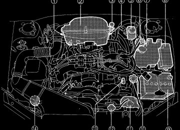
Engine compartment overview (cid:132) 2.5 liter models
4 5 6 7
14
13
12
11
10
UBB036BB
11-8
22)
38)
36)
1) Manual transmission oil level
gauge (MT) (page 11-27) or Dif- ferential gear oil level gauge (AT) (page 11-30)
2) Air cleaner element (page 11-
3) Clutch fluid reservoir (page 11-
4) Automatic transmission fluid lev-
el gauge (page 11-28)
5) Brake fluid reservoir (page 11-
6) Fuel filter 7) Windshield washer tank (page
8) Fuse box (page 11-59) 9) Battery (page 11-58) 10) Engine oil filler cap (page 11-11) 11) Engine coolant reservoir (page
12) Radiator cap (page 11-18) 13) Engine oil level gauge (page 11-
11-51)
11-18)
11)
14) Power steering fluid reservoir
(page 11-35)
(cid:132) 2.5 liter CALIFORNIA spec models
13
12
11
10
9 8