- 2006 Subaru Legacy Owners Manuals
- Subaru Legacy Owners Manuals
- 2004 Subaru Legacy Owners Manuals
- Subaru Legacy Owners Manuals
- 2008 Subaru Legacy Owners Manuals
- Subaru Legacy Owners Manuals
- 2005 Subaru Legacy Owners Manuals
- Subaru Legacy Owners Manuals
- 2007 Subaru Legacy Owners Manuals
- Subaru Legacy Owners Manuals
- 2000 Subaru Legacy Owners Manuals
- Subaru Legacy Owners Manuals
- 2003 Subaru Legacy Owners Manuals
- Subaru Legacy Owners Manuals
- 2012 Subaru Legacy Owners Manuals
- Subaru Legacy Owners Manuals
- 2001 Subaru Legacy Owners Manuals
- Subaru Legacy Owners Manuals
- 2010 Subaru Legacy Owners Manuals
- Subaru Legacy Owners Manuals
- 2011 Subaru Legacy Owners Manuals
- Subaru Legacy Owners Manuals
- 2009 Subaru Legacy Owners Manuals
- Subaru Legacy Owners Manuals
- 2002 Subaru Legacy Owners Manuals
- Subaru Legacy Owners Manuals
- Download PDF Manual
-
4. Remove the bulb from the socket. Rear turn signal light: Remove the bulb from the socket by pushing it and turning it counterclockwise. Others: Pull the bulb out of the socket. 5. Install a new bulb in the socket. 6. Set the bulb socket into the rear combination light
11-72
assembly and turn it clockwise until it locks. 7. Close the cover and latch the clock. (cid:84) Station wagon (cid:86) Brake/tail and rear turn signal light bulbs It may be difficult to replace the bulbs. It is recom- mended that you have the bulbs replaced by your SUBARU dealer.
UBB021BB
1) Service holes 1. Remove the light bulb replacement service hole covers at two places by prying the edge of the cover with a regular screwdriver.
2Maintenance and service
UBB022BB
UBB070BB
1) Nuts 2. Remove the upper and lower nuts. Then, slide the rear combination lamp assembly to the rear and re- move it from the vehicle. 3. Using a Phillips screwdriver, remove the upper and lower screws that secure the side cover of the rear combination light assembly.
1) Rear turn signal light bulb 2) Brake/tail light bulb 4. Remove the bulb socket from the rear combination light assembly by turning it counterclockwise.
– CONTINUED – 11-73
2Maintenance and service
Turn signal light bulb
11-74
UBB048BA
UBB025BA
Brake/tail light bulb 5. Remove the bulb from the socket. Turn signal light: Pull the bulb out of the socket. Brake/tail light: Remove the bulb from the socket by pushing it and turning it counterclockwise. 6. Install a new bulb in the socket. 7. Set the bulb holder into the rear combination light assembly and turn it clockwise until it locks. 8. Using a Phillips screwdriver, install the side cover to the rear combination light assembly. 9. Fit the rear combination light assembly into the ve- hicle body and tighten the nuts from the interior of the vehicle.
10.Reinstall the light bulb replacement service hole covers. (cid:86) Back-up and brake/tail light bulbs
UBB026BC
1) Back-up light bulb 2) Brake/tail light bulb 1. Unlatch the rear finisher light cover by moving the knob upward. Open the cover up. 2. Remove the bulb socket from the rear finisher light assembly by turning it counterclockwise.
2Maintenance and service
UBB025BA
3. Remove the bulb from the socket by pushing it and turning counterclockwise. Install a new bulb in the socket. 4. Set the bulb holder into the rear finisher light as- sembly and turn it clockwise until it locks. 5. Close the cover and latch the lock.
– CONTINUED – 11-75
2Maintenance and service
(cid:132) License plate light
11-76
1. Remove the mounting screws using a phillips screwdriver. 2. Remove the cover and lens. 3. Pull the bulb out of the socket. Install a new bulb. 4. Reinstall the lens and cover. 5. Tighten the mounting screws.
(cid:132) Map light, dome light, luggage com-
partment light and door step light
UBF013EA
UBB027BA
Map light (without moonroof model)
UBB029BA
2Maintenance and service
Map light (with moonroof model)
Dome light
UBB068BA
HSB088BA
– CONTINUED – 11-77
2Maintenance and service
UBB067BB
UBS037AA
Luggage compartment light 1) Bulb
Door step light 1. Remove the lens by prying the edge of the lens with a regular screwdriver. 2. Pull the bulb out of the socket. Install a new bulb. 3. Reinstall the lens.
11-78
(cid:132) Trunk light
(cid:132) High mount stop light (cid:84) Sedan
2Maintenance and service
UBF014FA
1. Remove the cover by squeezing its sides and pull- ing it. 2. Pull the bulb out of the socket. Install a new bulb. 3. Reinstall the cover.
OM-U2350
1. Remove the high mount stop light cover by prying on the edge with a screwdriver. 2. Pull the bulb out of the socket. Install a new bulb. 3. Reinstall the cover.
– CONTINUED – 11-79
2Maintenance and service
(cid:84) Station wagon
UBB028BA
1. Remove the mounting screw covers by prying on the edge with a screwdriver. 2. Remove the mounting screws using a phillips screwdriver and then remove the high mount stop light cover. 3. Pull the bulb out of the socket. Install a new bulb. 4. Reinstall the cover. 5. Tighten the mounting screws then reinstall the cov- ers. NOTE Other bulbs may be difficult to replace. Have your SUBARU dealer replace these bulbs if necessary.
11-80
Specifications
Dimensions ....................................................... Engine ................................................................ Electrical system .............................................. Capacities .......................................................... Tires ................................................................... Wheel alignment ...............................................
Specifications ................................................ 12-2
12-2
12-3
12-3
12-4
12-5
12-5
Fuses and circuits ........................................ 12-6
12-6
12-9
Bulb chart ...................................................... 12-12
Vehicle identification .................................... 12-13Fuse panel located behind the coin tray ........ Fuse panel located in the engine compartment ..................................................
12
12-1
Specifications
SpecificationsSpecifications These specifications are subject to change without notice.
(cid:132) Dimensions
Item
Legacy
OUTBACK
Sedan
Wagon
Sedan
Wagon
2.5-liter
2.5-liter
3.0-liter
2.5-liter
3.0-liter
in (mm)
184.4 (4,685 ) 187.4 (4,760) 68.7 (1,745) 68.7 (1,745) 55.7 (1,415) 56.6 (1,435), 59.6 (1,525)* 104.3 (2,650) 104.3 (2,650) 57.5 (1,460) 57.5 (1,460) 57.5 (1,460) 57.3 (1,455)
6.1 (155)
6.3 (160)
184.4 (4,685) 68.7 (1,745) 58.3 (1,480)
104.3 (2,650) 57.9 (1,470) 57.7 (1,465)
7.3 (185)
187.4 (4,760) 68.7 (1,745) 62.2 (1,580)
104.3 (2,650) 57.9 (1,470) 57.7 (1,465)
7.3 (185)
7.9 (200)
Overall length Overall width Overall height
Wheel base Tread
Front Rear
Ground clearance
*: With roof rail
12-2
(cid:132) Engine Engine model
Engine type
Displacement cc (cu-in) Bore × Stroke in (mm)
Compression ratio Firing order (cid:132) Electrical system Battery type and capacity
Alternator
Spark plugs
*: CALIFORNIA spec models
Specifications
EJ251, EJ259
(2.5 liter)
EZ30D (3.0 liter)
Horizontally opposed, liquid cooled 4 cyl-
inder, 4 stroke gasoline engine
Horizontally opposed, liquid cooled 6 cyl-
inder, 4 stroke gasoline engine
2,457 (150) 3.92 x 3.11
(99.5 x 79.0)10.0 : 1
1 – 3 – 2 – 4
MT AT
2.5 liter
3.0 liter 2.5 liter 3.0 liter 2.5 liter
3.0 liter
3,000 (183.0) 3.51 x 3.15
(89.2 x 80.0)10.7 : 1
1 – 6 – 3 – 2 – 5 – 4
55D23L 75D23L 75D23L 12V-90A 12V-100A
RC10YC4 (Champion)
BKR6E-11 (NGK) BKR5E-11 (NGK) FR5AP-11 (NGK)* PLFR6A-11 (NGK)
– CONTINUED – 12-3
2.5 liter 3.0 liter
L-S (AT), L (AT) Others
2.5 liter
3.0 liter
MT AT
16.9 US gal (64 liters, 14.1 Imp gal)
4.2 US qt (4.0 liters, 3.5 Imp qt) 5.6 US qt (5.3 liters, 4.6 Imp qt) 3.7 US qt (3.5 liters, 3.1 Imp qt) 9.8 US qt (9.3 liters, 8.2 Imp qt) 1.3 US qt (1.2 liters, 1.1 Imp qt) 0.9 US qt (0.9 liter, 0.8 Imp qt) 0.8 US qt (0.8 liter, 0.7 Imp qt) 0.7 US qt (0.7 liter, 0.6 Imp qt) 7.2 US qt (6.8 liters, 6.0 Imp qt) 7.1 US qt (6.7 liters, 5.9 Imp qt) 8.4 US qt (7.9 liters, 7.0 Imp qt)
Specifications
(cid:132) Capacities Fuel tank Engine oil
Transmission oil (MT) Transmission fluid (AT) AT differential gear oil Rear differential gear oil
Power steering gear fluid Engine coolant
12-4
(cid:132) Tires Tire size Wheel size Pressure
Temporary spare tire
Front Rear Rear at trailer towing Size Pressure
(cid:132) Wheel alignment
Item
Front Rear Front Rear
Toe
Camber
Specifications
P205/55R16 89H
P225/60R16 97H
16 x 61/2JJ
30 psi (210 kPa, 2.1 kg/cm2) 29 psi (200 kPa, 2.0 kg/cm2) 32 psi (220 kPa, 2.2 kg/cm2)
P205/60R15 90H
15 x 6JJ
32 psi (220 kPa, 2.2 kg/cm2) 30 psi (210 kPa, 2.1 kg/cm2)
–
T135/70R16
T145/80R16
60 psi (420 kPa, 4.2 kg/cm2)
Legacy
OUTBACK
Sedan
Wagon
Sedan
Wagon
0 in (0 mm) 0 in (0 mm)
–0°05’
–0°30’
–0°20’
0°20’ –0°10’
– CONTINUED – 12-5
Specifications
Fuses and circuits (cid:132) Fuse panel located behind the coin
tray
(cid:84) 2.5 liter models
13
14
15
16
17
18
19
10
11
12
20
21
12-6
HBC001DB
Fuse panel
Fuse rating
Circuit
10
11
15A
15A
15A
20A
10A
15A
15A
30A
15A
15A
15A
(cid:121) Heater fan
(cid:121) Heater fan
(cid:121) Power door lock (cid:121) Keyless entry
(cid:121) Mirror heater (cid:121) Cigarette lighter (cid:121) Remote controlled rear
view mirrors
(cid:121) Tail light (cid:121) Parking light
(cid:121) SRS airbag
(cid:121) Front fog light
(cid:121) ABS solenoid
(cid:121) Radio (cid:121) Clock
(cid:121) Trailer
(cid:121) Engine ignition system (cid:121) SRS airbag
Fuse panel
Fuse rating
Circuit
(cid:84) 3.0 liter models
12
13
14
15
16
17
18
19
20
21
10A
15A
10A
30A
20A
15A
15A
20A
20A
15A
(cid:121) Illumination brightness
control
(cid:121) Fuel pump
(cid:121) Rear window wiper and
washer
(cid:121) Windshield wiper and
washer
(cid:121) Brake light
(cid:121) Air conditioner
(cid:121) Backup light (cid:121) Cruise control (cid:121) ABS control
(cid:121) Wiper deicer
13
14
15
16
17
18
19
10
11
12
20
21
(cid:121) Accessory power sock-
et
(cid:121) Seat heater
Specifications
UBC001CB
(cid:121) Ignition coil and ignitor
(CALIFORNIA spec vehicle only)
Fuse panel
Fuse rating
Circuit
15A
(cid:121) Heater fan
– CONTINUED – 12-7
Specifications
Fuse panel
Fuse rating
Circuit
Fuse panel
Fuse rating
Circuit
13
14
15
16
17
18
19
20
21
15A
10A
30A
20A
15A
15A
20A
20A
20A
15A
15A
20A
10A
15A
15A
30A
15A
15A
15A
10A
(cid:121) Heater fan
(cid:121) Power door lock (cid:121) Keyless entry
(cid:121) Cigarette lighter (cid:121) Remote controlled rear
view mirrors (cid:121) Mirror heater
(cid:121) Tail light (cid:121) Parking light
(cid:121) SRS airbag
(cid:121) Front fog light
(cid:121) ABS (VDC) solenoid
(cid:121) Radio (cid:121) Clock
(cid:121) Trailer
(cid:121) Engine ignition system (cid:121) SRS airbag
(cid:121) Illumination brightness
control
10
11
12
12-8
(cid:121) Fuel pump
(cid:121) Rear window wiper and
washer
(cid:121) Windshield wiper and
washer
(cid:121) Brake light
(cid:121) Air conditioner
(cid:121) Backup light (cid:121) Cruise control (cid:121) ABS (VDC) control
(cid:121) Wiper deicer
(cid:121) McIntosh audio amp (if
equipped)
(cid:121) Accessory power sock-
et
(cid:121) Seat heater
(cid:132) Fuse panel located in the engine com-
partment
(cid:84) 2.5 liter models
10
11
12A) FWD socket (without SPORTSHIFT mode) B) Main fuse
UBC003BB
Specifications
Fuse panel
Fuse rating
Circuit
10
11
20A
20A
30A
20A
15A
15A
10A
10A
15A
15A
20A
(cid:121) Radiator cooling fan
(Main)
(cid:121) Radiator cooling fan
(Sub)
(cid:121) ABS motor
(cid:121) Rear window defogger
(cid:121) Hazard warning flasher (cid:121) Horn
(cid:121) Meter (cid:121) SRS airbag system
warning light
(cid:121) Automatic transmis-
sion control unit
(cid:121) ABS UNIT
(cid:121) Alternator
(cid:121) Headlight (right side)
(cid:121) Headlight (left side)
(cid:121) Lighting switch
– CONTINUED – 12-9
Specifications
Fuse panel
Fuse rating
Circuit
12
15A
(cid:121) Clock (cid:121) Interior light
(cid:84) 3.0 liter models
10
11
12
13A) FWD socket (without VDC model) B) Main fuse
UBC004BC
12-10
Fuse panel
Fuse rating
Circuit
Fuse panel
Fuse rating
Circuit
Specifications
10
30A
30A
30A 50A
30A
20A
15A
15A
10A
10A
15A
11
12
13
15A
20A
15A
(cid:121) Headlight (left side)
(cid:121) Lighting switch
(cid:121) Clock (cid:121) Interior light
(cid:121) Radiator cooling fan
(Main)
(cid:121) Radiator cooling fan
(Sub)
(cid:121) ABS motor (cid:121) VDC motor
(cid:121) McIntosh audio amp (if
equipped)
(cid:121) Rear window defogger
(cid:121) Hazard warning flasher (cid:121) Horn
(cid:121) Meter (cid:121) SRS airbag system
warning light
(cid:121) Automatic transmis-
sion control unit
(cid:121) ABS UNIT
(cid:121) Alternator
(cid:121) Headlight (right side)
– CONTINUED – 12-11
Specifications
Bulb chart
Description Headlight
GT and OUTBACK
Low beam High beam
Except GT and OUT- BACK
Front turn signal
Spot light Dome light Door step light Parking and front side marker light Front fog light
Except OUTBACK OUTBACK
Backup light
Sedan Station wagon Luggage area light High mount stop light
Sedan
12-12
Description
Station wagon
Rear turn signal light
Sedan Station wagon
Brake/tail light
Sedan Station wagon Licence plate light
Sedan Station wagon
Trunk room light
Wattage 12V-13W
12V-21W 12V-21W
Bulb No. 912
– R2172 7440
12V-27/8W 3157K 12V-27/8W 1157
12V-5W 12V-3.8W or 5W 12V-5W
168
194 or 168W5W
Wattage
Bulb No.
H1
12V-55W 12V-60W 9005 (HB3) 12V-65/55W 9007 (HB5)12V-27W
1156NA (Amber) 12V-8W – 12V-8W – 12V-3.4W – 12V-27/8W 1157NA (Amber)
12V-55W 12V-51W
12V-27W 12V-27W 12V-13W
H3
9006 (HB4)3156K 1156
–12V-16W
921
Vehicle identification
Specifications
1) Emission control label 2) Vehicle identification number 3) Radio noise label (Canada mod-
4) Tire inflation pressure label 5) Certification and bar code label 6) Vehicle identification number
el)
plate
7) Model number plate
UBC009BB
– CONTINUED – 12-13
Consumer information and Reporting safety defects
Tire information ............................................. 13-2
13-2
Tire labeling ....................................................... 13-5
Recommended tire inflation pressure ............ 13-7
Glossary of tire terminology ............................ Tire care – maintenance and safety 13-8
practices ......................................................... 13-9
Vehicle load limit – how to determine ............. Determining compatibility of tire and vehicle load capacities ............................................... 13-13
Adverse safety consequences of overloading on handling and stopping and on tires ........ 13-14
Steps for Determining Correct Load Limit ..... 13-14
Uniform tire quality grading standards ....... 13-15
Treadwear .......................................................... 13-15
Traction AA, A, B, C .......................................... 13-15
Temperature A, B, C ......................................... 13-16
Reporting safety defects (USA) ................... 13-1713
13-1
Consumer information and Reporting safety defects
Consumer information and Reporting safety defects
For U.S.A. The following information has been compiled accord- ing to Code of Federal Regulations “Title 49, Part 575”.
vide more dimensional information about the tire size. Example:
Tire information (cid:132) Tire labeling Many markings (e.g. Tire size, Tire Identification Number or TIN) are placed on the sidewall of a tire by tire manufacturers. These marking can provide you with useful information on the tire. (cid:84) Tire size Your vehicle comes equipped with P-Metric tire size. It is important to understand the sizing sys- tem in selecting the proper tire for your vehicles. Here is a brief review of the tire sizing system with a breakdown of its individual elements. (cid:86) P Metric With the P-Metric system, Section Width is mea- sured in millimeters. To convert millimeters into inches, divide by 25.4. The Aspect Ratio (Sec- tion Height divided by Section Width) helps pro-
13-2
(4)
(3)
(2)
P 225 / 60 R 16
(1) (5) (1) P = Certain tire type used on light duty vehi- cles such as passenger cars (2) Section Width in millimeters (3) Aspect Ratio (= section height ÷ section width). (4) R = Radial Construction (5) Rim diameter in inches (cid:86) Load and Speed Rating Descriptions The load and speed rating descriptions will ap- pear following the size designation. They provide two important facts about the tire. First, the number designation is its load index. Second, the letter designation indicates the tire’s speed rating.Example:
P 225 / 60 R 16 97 H (7)
Size designation
(6)
(6) Load Index: A numerical code which specifies the maximum load a tire can carry at the speed indicated by its speed symbol, at maximum infla- tion pressure. For example, “97” means 1,609 lbs (730 kg), “90” means 1,323 lbs (600 kg), “89” means 1,278 lbs (580 kg)
Load indices apply only to the tire, not to the vehicle. Putting a load rated tire on any car does not mean the car can be loaded up to the tire’s rated load.
(7) Speed Rating: An alphabetical system de- scribing a tire’s capability to travel at established and predetermined speeds. For example, “H” means 130 mph (210 km/h)
Consumer information and Reporting safety defects
(cid:121) Speed ratings apply only to the tire, not to the vehicle. Putting a speed rated tire on any car does not mean the car can be op- erated at the tire’s rated speed. (cid:121) The speed rating is void if the tires are worn out, damaged, repaired, retreaded, or otherwise altered from their original condi- tion. If tires are repaired, retreaded, or oth- erwise altered, they may not be suitable for original equipment tire designed loads and speeds.
(cid:84) Tire Identification Number (TIN) Tire Identification Number (TIN) is marked on the intended outboard sidewall. The TIN is com- posed of four groups. Here is a brief review of the TIN with a breakdown of its individual elements.
DOT XX XX XXX XXXX
(1)
(2)
(3)
(4)
(1) Manufacturer’s Identification Mark
– CONTINUED – 13-3
Consumer information and Reporting safety defects
(2) Tire Size (3) Tire Type Code (4) Date of Manufacture The first two figures identify the week, starting with “01” to represent the first full week of the cal- endar year; the second two figures represent the year. For example, 0101 means the 1st week of 2001. (cid:84) Other markings The following makings are also placed on the sidewall. (cid:86) Maximum permissible inflation pressure The maximum cold inflation pressure to which this tire may be inflated. For example, “300 kpa (44 PSI) MAX. PRESS” (cid:86) Maximum load rating The load rating at the maximum permissible weight load for this tire. For example, “MAX. LOAD 730 kg (1609 LBS) @ 300 kpa (44 PSI) MAX. PRESS.”
13-4
Maximum load rating applies only to the tire, not to the vehicle. Putting a load rated tire on any car does not mean the car can be loaded up to the tire’s rated load.
(cid:86) Construction type Applicable construction of this tire. For example, “TUBELESS STEEL BELTED RA- DIAL” (cid:86) Construction The generic name of each cord material used in the plies (both sidewall and tread area) of this tire. For example, “PLIES: TREAD 2 STEEL + 2
POLYESTER + 1 NYLON SIDEWALL 2 POLY- ESTER” (cid:86) Uniform Tire Quality Grading (UTQG) For details, refer to “Uniform tire quality grading standards” in this chapter.Consumer information and Reporting safety defects
(cid:132) Recommended tire inflation pressure (cid:84) Recommended cold tire inflation pressure Recommended cold tire inflation pressure for your vehicle’s tires is as follows,
Tire size Wheel size Pressure
Temporary spare tire
P205/60R15 90H
P205/55R16 89H
P225/60R16 97H
15 x 6JJ
32 psi (220 kpa, 2.2 kg/cm2)
30psi (210 kpa, 2.1 kg/cm2)
–
16 x 6 1/2JJ 30 psi (210 kpa, 2.1 kg/cm2) 29 psi (200 kpa, 2.0 kg/cm2) 32 psi (220 kpa, 2.2 kg/cm2)
T135/70R16
T145/80R16
60 psi (420 kpa, 4.2 kg/cm2)
Front
Rear
Rear at trailer towing Size Pressure
– CONTINUED – 13-5
Consumer information and Reporting safety defects
(cid:84) Vehicle placard
Example:
TIRE AND LOADING INFORMATION
SEATING CAPACITY
TOTAL 5
FRONT 2
REAR 3
The combined weight of occupants and cargo should never exceed 386kg or 850 lbs. ORIGINAL TIRE SIZE P225/60R16
COLD TIRE INFLATION PRESSURE FRONT 210 kPa,30 PSI REAR 200 kPa,29 PSI COLD TIRE INFLATION PRESSURE
SEE OWNER’S MANUAL FOR ADDITIONAL INFORMATION
COMPACT SPARE TIRE
T145/80R16
420 kPa,60 PSI
UB8052BA
UBD008AA
The vehicle placard is affixed to the driver’s side B-pillar.
13-6
The vehicle placard shows original tire size, rec- ommended cold tire inflation pressure on each tire at maximum loaded vehicle weight, seating capacity and loading information. (cid:84) Adverse safety consequences of under-in-
flation
Driving at high speeds with excessively low tire pressures can cause the tires to flex severely and to rapidly become hot. A sharp increase in temperature could cause tread separation, and failure of the tire(s). Possible resulting loss of ve-
hicle control could lead to an accident. (cid:84) Measuring and adjusting air pressure to
achieve proper inflation
Check and, if necessary, adjust the pressure of each tire (including the spare) at least once a month and before any long journey. Check the tire pressures when the tires are cold. Use a pressure gauge to adjust the tire pressures to the specific values. Driving even a short distance warms up the tires and increases the tire pres- sures. Also, the tire pressures are affected by the ambient temperature. It is best to check tire pres- sure outdoors before driving the vehicle. When a tire becomes warm, the air inside it expands, causing the tire pressure to increase. Be careful not to mistakenly release air from a warm tire to reduce its pressure.
(cid:132) Glossary of tire terminology (cid:121) Cold tire pressure The pressure in a tire that has been driven less than 1 mile or has been standing for three hours or more. (cid:121) Maximum inflation pressure
Consumer information and Reporting safety defects
The maximum cold inflation pressure to which a tire may be inflated. (cid:121) Recommended inflation pressure The cold inflation pressure recommended by a vehicle manufacturer. (cid:121) Intended outboard sidewall
1)The sidewall that contains a whitewall, bears white lettering or bears manufacturer, brand, and/or model name molding that is higher or deeper than the same molding on the other sidewall of the tire, or 2)The outward facing sidewall of an asymmet- rical tire that has a particular side that must al- ways face outward when mounting on a vehi- cle.
(cid:121) Accessory weight The combined weight (in excess of those stan- dard items which may be replaced) of floor mats, leather seats and cross bars to the extent that these items are available as factory-installed equipment (whether installed or not). (cid:121) Curb weight The weight of a motor vehicle with standard equipment including the maximum capacity of fu- el, oil, and coolant and air conditioning.
– CONTINUED – 13-7
Consumer information and Reporting safety defects
(cid:121) Maximum loaded vehicle weight The sum of curb weight, accessory weight, vehi- cle capacity weight and production options weight. (cid:121) Normal occupant weight 150 lbs (68 kg) times the number of occupants (3
occupants). (cid:121) Occupant distribution Distribution of occupants in a vehicle, 2 in front, 1 in rear seat. (cid:121) Production options weight The combined weight of those installed regular production options weighing over 5.1lbs (2.3 kg) in excess of those standards items which they replace, not previously considered in curb weight or accessory weight. (cid:121) Vehicle capacity weight The total weight of cargo, luggage and occu- pants that can be added to the vehicle. (cid:121) Vehicle maximum load on a tire Load on an individual tire that is determined by distributing to each axle its share of the maxi- mum loaded vehicle weight and dividing by two. (cid:121) Vehicle normal load on a tire Load on an individual tire that is determined by13-8
distributing to each axle its share of the curb weight, accessory weight, and normal occupant weight and dividing by two.
(cid:132) Tire care – maintenance and safety
practices
(cid:121) Check on a daily basis that the tires are free from serious damage, nails, and stones. At the same time, check the tires for abnormal wear. (cid:121) Inspect the tire tread regularly and replace the tires before their tread wear indicators become visible. When a tire’s tread wear indicator be- comes visible, the tire is worn beyond the ac- ceptable limit and must be replaced immediately. With a tire in this condition, driving at even low speeds in wet weather can cause the vehicle to hydroplane. Possible resulting loss of vehicle control can lead to an accident. (cid:121) To maximize the life of each tire and ensure that the tires wear uniformly, it is best to rotate the tires every 7,500 miles (12,500 km). Rotating the tires involves switching the front and rear tires on the right-hand side of the vehicle and similarly switching the front and rear tires on the
left-hand side of the vehicle. (Each tire must be kept on its original side of the vehicle.) Replace any damaged or unevenly worn tire at the time of rotation. After tire rotation, adjust the tire pres- sures and make sure the wheel nuts are correct- ly tightened. A tightening torque specification and a tightening sequence specification for the wheel nuts can be found “Flat tires” in Chapter 9.
(cid:132) Vehicle load limit – how to determine The load capacity of your vehicle is determined by weight, not by available cargo space. The load limit of your vehicle is shown on the vehicle placard attached to the driver’s side B-pillar. Lo- cate the statement “The combined weight of oc- cupants and cargo should never exceed XXX kg or XXX lbs” on your vehicle’s placard. The vehicle placard also shows seating capacity of your vehicle. The total load capacity includes the total weight of driver and all passengers and their belong- ings, any cargo, any optional equipment such as a trailer hitch, roof rack or bike carrier, etc., and the tongue load of a trailer. Therefore cargo ca-
Consumer information and Reporting safety defects
pacity can be calculated by the following method. Cargo capacity = Load limit – (total weight of oc- cupants + total weight of optional equipment + tongue load of a trailer (if applicable)) For towing capacity information and weight lim- its, refer to “Trailer towing” in Chapter 8. (cid:84) Calculating total and load capacities vary-
ing seating configurations
Calculate the available load capacity as shown in the following examples: Example 1A
UBD009BA
– CONTINUED – 13-9
Consumer information and Reporting safety defects
Vehicle capacity weight of the vehicle is 800 lbs (363 kg), which is indicated on the vehicle plac- ard with the statement “The combined weight of occupants and cargo should never exceed 363
kg or 800 lbs”. For example, if the vehicle has one occupant weighing 154 lbs (70 kg) plus cargo weighing 551 lbs (250 kg). 1. Calculate the total weight.Total weight = 154 lbs (70 kg) + 551 lbs (250 kg)
(Occupant)
(Cargo)
= 705 lbs (320 kg) 2. Calculate the available load capacity by sub- tracting the total weight from the vehicle capacity weight of 800 lbs (363 kg).
13-10
Available Load Capacity = 800 lbs (363 kg) – 705 lbs (320 kg)
(Vehicle
capacity weight)
(Total weight)
= 95 lbs (43 kg) 3. The result of step 2 shows that a further 95 lbs (43 kg) of cargo can be carried. Example 1B
For example, if a person weighing 176 lbs (80
kg) now enters the same vehicle (bringing theUB8054BA
Consumer information and Reporting safety defects
number of occupants to two), the calculations are as follows: 1. Calculate the total weight.
Example 2A
Total weight = 154 lbs (70 kg) + 176 lbs (80 kg)
(Occupant)
+ 551 lbs (250 kg)
(Cargo)
= 881 lbs (400 kg)
2. Calculate the available load capacity.
Available Load Capacity = 800 lbs (363 kg) – 881 lbs (400 kg)
(Vehicle
capacity weight)
(Total weight)
= – 81 lbs (–37 kg) 3. The total weight now exceeds the capacity weight by 81 lbs (37 kg), so the cargo weight must be reduced by 81 lbs (37 kg) or more.
UBD011BA
Vehicle capacity weight of the vehicle is 800 lbs (363 kg), which is indicated on the vehicle plac- ard with the statement “The combined weight of occupants and cargo should never exceed 363
kg or 800 lbs”. For example, the vehicle has one occupant weighing 165 lbs (75 kg) plus cargo weighing 265 lbs (120 kg). In addition, the vehicle is fitted with a trailer hitch weighing 22 lbs (10 kg), to which is attached a trailer weighing 1764 lbs (800kg). 10% of the trailer weight is applied to – CONTINUED – 13-11Consumer information and Reporting safety defects
the trailer tongue (i.e. Tongue load = 176 lbs (80
kg)). 1. Calculate the total weight.Example 2B
Total weight = 165 lbs (75 kg) + 265 lbs (120 kg)
(Occupant)
(Cargo)
+ 22 lbs (10 kg) + 176 lbs (80 kg)
(Trailer hitch)
(Tongue load)
= 628 lbs (285 kg) 2. Calculate the available load capacity.
Available Load Capacity = 800 lbs (363 kg) – 628 lbs (285 kg)
(Vehicle
capacity weight) = 172 lbs (78 kg)
(Total weight)
3. The result of step 2 shows that a further 172
lbs (78 kg) of cargo can be carried.13-12
UBD010BA
For example, if a person weighing 143 lbs (65
kg) and a child weighing 40 lbs (18 kg) now enter the same vehicle (bringing the number of occu- pants to three), and a child restraint system weighing 11 lbs (5 kg) is installed in the vehicle for the child to use, the calculations are as fol- lows: 1. Calculate the total weight.Total weight = 165 lbs (75 kg) + 143 lbs (65 kg) + 40 lbs (18 kg)
(Occupant)
+ 11 lbs (5 kg) + 265 lbs (120 kg)
(Child restraint)
(Cargo)
+ 22 lbs (10 kg) + 176 lbs (80 kg)
(Trailer hitch)
(Tongue load)
= 822 lbs (373 kg)
2. Calculate the available load capacity.
Available Load Capacity = 800 lbs (363 kg) – 882 lbs (373 kg)
(Vehicle
capacity weight)
(Total weight)
= – 22 lbs (–10 kg) 3. The total weight now exceeds the capacity weight by 22 lbs (10 kg), so the cargo weight must be reduced by 22 lbs (10kg) or more.
Consumer information and Reporting safety defects
(cid:132) Determining compatibility of tire and
vehicle load capacities
The sum of four tires’ maximum load ratings must exceed the maximum loaded vehicle weight (“GVWR”). In addition, sum of the maxi- mum load ratings of two front tires and of two rear tires must exceed each axle’s maximum loaded capacity (“GAWR”). Original equipment tires are designed to fulfill those conditions. The maximum loaded vehicle weight is referred to Gross Vehicle Weight Rating (GVWR). And each axle’s maximum loaded capacity is referred to Gross Axle Weight Rating (GAWR). The GVWR and each axle’s GAWR are shown on the vehicle certification label affixed to the driver’s door. The GVWR and front and rear GAWRs are de- termined by not only the maximum load rating of tires but also loaded capacities of the vehicle’s suspension, axles and other body parts. Therefore, this means that the vehicle cannot necessarily be loaded up to the tire’s maximum load rating on the tire sidewall.
– CONTINUED – 13-13
Consumer information and Reporting safety defects
(cid:132) Adverse safety consequences of over- loading on handling and stopping and on tires
Overloading could affect vehicle handling, stop- ping distance, vehicle and tire as shown bellow. This could lead to an accident and possibly result in severe personal injury. (cid:121) Vehicle stability will deteriorate. (cid:121) Heavy and/or high-mounted loads could in- crease the risk of rollover. (cid:121) Stopping distance will increase. (cid:121) Brakes could overheat and fail. (cid:121) Suspension, bearings, axles and other body parts could break or experience accelerated wear that will shorten vehicle life. (cid:121) Tires could fail. (cid:121) Tread separation could occur. (cid:121) Tire could separate from its rim.
(cid:132) Steps for Determining Correct Load
Limit
1. Locate the statement “The combined weight of occupants and cargo should never exceed XXX pounds” on your vehicle’s placard.
13-14
2. Determine the combined weight of the driver and passengers that will be riding in your vehicle. 3. Subtract the combined weight of the driver and passengers from XXX kilograms or XXX pounds. 4. The resulting figure equals the available amount of cargo and luggage load capacity. For example, if the “XXX” amount equals 1,400 lbs (635kg). and there will be five- 150 lbs (68 kg) passengers in your vehicle, the amount of avail- able cargo and luggage load capacity is 650 lbs. (1,400 – 750 (5 x 150) = 650 lbs.) 5. Determine the combined weight of luggage and cargo being loaded on the vehicle. That weight may not safely exceed the available car- go and luggage load capacity calculated in Step 4. 6. If your vehicle will be towing a trailer, load from your trailer will be transferred to your vehi- cle. Consult this manual to determine how this reduces the available cargo and luggage load capacity of your vehicle.
Uniform tire quality grading stan- dards This information indicates the relative perfor- mance of passenger car tires in the area of treadwear, traction, and temperature resistance. This is to aid the consumer in making an in- formed choice in the purchase of tires. Quality grades can be found where applicable on the tire sidewall between tread shoulder and maximum section width. For example: Treadwear 200 Traction AA Temperature A The quality grades apply to new pneumatic tires for use on passenger cars. However, they do not apply to deep tread, winter type snow tires, space-saver or temporary use spare tires, tires with nominal rim diameters of 12 inches or less, or to some limited production tires. All passenger car tires must confirm to Federal Safety Requirements in addition to these grades.
(cid:132) Treadwear The treadwear grade is a comparative rating
Consumer information and Reporting safety defects
based on the wear rate of the tire when tested under controlled conditions on a specified gov- ernment test course. For example, a tire graded 150 would wear one and one-half (1-1/2) times as well on the govern- ment course as a tire graded 100. The relative performance of tires depends upon the actual conditions of their use, however, and may depart significantly from the norm due to variations in driving habits, service practices and differences in road characteristics and climate.
(cid:132) Traction AA, A, B, C The traction grades, from highest to lowest, are AA, A, B and C. Those grades represent the tire’s ability to stop on wet pavement as mea- sured under controlled conditions on specified government test surfaces of asphalt and con- crete. A tire marked C may have poor traction performance.
The traction grade assigned to this tire is based on straight-ahead braking traction – CONTINUED – 13-15
Consumer information and Reporting safety defects
tests, and does not include acceleration, cornering, hydroplaning, or peak traction characteristics.
and not overloaded. Excessive speed, un- derinflation, or excessive loading, either separately or in combination, can cause heat buildup and possible tire failure.
(cid:132) Temperature A, B, C The temperature grades are A (the highest), B, and C, representing the tire’s resistance to the generation of heat and its ability to dissipate heat when tested under controlled conditions on a specified indoor laboratory test wheel. Sustained high temperature can cause the material of the tire to degenerate and reduce tire life, and exces- sive temperature can lead to sudden tire failure. The grade C corresponds to a level of perfor- mance which all passenger car tires must meet under the Federal Motor Vehicle Safety Stan- dards No. 109. Grades B and A represent higher levels of performance on the laboratory test wheel than the minimum required by law.
The temperature grade for this tire is es- tablished for a tire that is properly inflated
13-16
Reporting safety defects (USA) If you believe that your vehicle has a defect which could cause a crash or could cause in- jury or death, you should immediately inform the National Highway Traffic Safety Admin- istration (NHTSA) in addition to notifying Subaru of America, Inc. If NHTSA receives similar complaints, it may open an investigation, and if it finds that a safety defect exists in a group of vehicles, it may order a recall and remedy campaign. However, NHTSA cannot become involved in individual problems between you, your dealer, or Subaru of America, Inc. To con- tact NHTSA, you may either call the Auto Safety Hotline toll-free at 1-800-424-9393
(or 366-0123 in the Washington D.C. area) or write to: NHTSA, U.S. Department of Transportation, Washington, D.C. 20590. You can also obtain other information about motor vehicle safety from the Hotline.Consumer information and Reporting safety defects
– CONTINUED – 13-17
Index
14
14-1
Index
ABS (Anti-lock Brake System) ...............................
7-32
Warning light ................................................. 3-13, 7-33
Accessories ......................................................... 5-3, 11-62
6-11
Accessory power outlet ............................................. Air cleaner element ..................................................... 11-22
Air conditioner operation .......................................... 4-10
4-21
Air filtration system ..................................................... Air flow selection .......................................................... 4-4
Aluminum wheels ........................................................ 11-51
5-2
Antenna system ........................................................... Anti-lock Brake System (ABS) ............................... 7-32
Arming the system ...................................................... 2-15
1-11
Armrest ............................................................................ Ashtray ............................................................................. 6-12
AT OIL TEMPerature warning light ...................... 3-12
5-4
Audio set ......................................................................... Auto-dimming mirror/compass ............................... 3-31
Automatic/Emergency Locking Retractor(A/ELR) .......................................................................
1-20
Automatic transmission ................................... 7-15, 7-21
Capacities ................................................................. 12-4
Fluid ............................................................................ 11-28
Selector lever ................................................ 7-16, 7-22
Shift lock release ......................................... 7-20, 7-28
3-12
Temperature warning light ................................14-2
Brake
Battery ............................................................................... 11-58
Jump starting ........................................................... 9-15
Replacement (Remote keyless entry system) .................................................................... 2-10Booster ....................................................................... 11-39
Fluid ............................................................................. 11-36
Pad and lining .......................................................... 11-41
Pedal ........................................................................... 11-39
Brake system ................................................................. 7-31
Warning light ............................................................ 3-14
Braking .............................................................................. 7-30Breaking-in of new brake pads and linings ....................................................................... 11-42
Tips .............................................................................. 7-30Brake pedal
Bulb
Free play .................................................................... 11-39
Reserve distance ................................................... 11-40Chart ............................................................................ 12-12
Replacing ................................................................... 11-63Capacities ........................................................................ 12-4
Cargo area light ............................................................ 6-2
Catalytic converter ....................................................... 8-4Center
Changing
Console ..................................................................... Ventilators .................................................................
6-6
4-2Flat tire ....................................................................... 9-5
Oil and oil filter ........................................................ 11-12
3-12Charge warning light .................................................. CHECK ENGINE warning light/
Malfunction indicator lamp ..................................
3-11
Checking
Brake pedal free play ........................................... 11-39
Brake pedal reserve distance ........................... 11-40
Clutch function ........................................................ 11-40
Clutch pedal free play .......................................... 11-41
Engine oil level ....................................................... 11-11
Fluid level ....................... 11-28, 11-35, 11-36, 11-38
Gear oil level ................................ 11-27, 11-30, 11-32
Child restraint systems ............................................... 1-37
1-41
1-48
2-22Installation with seatbelt ..................................... Lower and tether anchorages .......................... Child safety .................................................................... Locks ..........................................................................
Key .............................................................................. 3-5
Seatbelt ........................................................... 1-20, 3-10
6-10Cigarette lighter socket .............................................
Chime
Index
Cleaning
Aluminum wheels .................................................. 10-4
Interior ........................................................................ 10-7
4-19
Ventilator grille ........................................................Climate control system
Manual ....................................................................... 4-5
4-11
Automatic ................................................................. Clock ................................................................................. 3-18
Clutch fluid ...................................................................... 11-38
Clutch pedal ................................................................... 11-40
Coat hook ....................................................................... 6-20
Coin compartment ....................................................... 6-7
6-20
Convenience hook ...................................................... Convenient tie-down hooks ..................................... 6-24
Cooling system ............................................................. 11-17
Corrosion protection ......................................... 8-13, 10-5
Cruise control ................................................................ 7-42
Set indicator light ................................................... 3-18
6-8
Cup holder ......................................................................Daytime running light system ................................. Differential gear oil
Front ............................................................................ 11-30
Rear ............................................................................ 11-32
12-2
2-17Dimensions .................................................................... Disarming the system ................................................
3-21
14-3
Index
Disc brake pad wear warning indicators ............ 7-31
Dome light ............................................................ 6-2, 11-76
Door locks ....................................................................... 2-3
3-15
Door open warning lights ......................................... Drive belts ....................................................................... 11-26
DrivingDrinking ..................................................................... Drugs .......................................................................... Foreign countries .................................................. 8-6
Car/Mobile phone .................................................. Pets ............................................................................. Tips ............................................. 7-14, 7-19, 7-28, 8-6
Tired or sleepy ........................................................ Snowy and icy roads ............................................ 8-12Electrical system .......................................................... Emergency Locking Retractor (ELR) .................. Engine
12-3
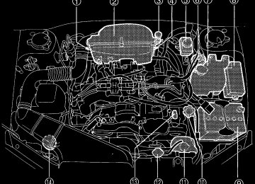
1-19Compartment overview ....................................... 11-8
Coolant ...................................................................... 11-18
Exhaust gas (Carbon monoxide) .................... 6, 8-3
Hood ...........................................................................