- Download PDF Manual
-
and operating the accelerator and brake pedals. If they do, do not use the electrical appliance while driving.
If the socket has been used for electrical appliances, damage may have been done to the internal mecha- nism that cause a cigarette lighter to “pop-out” after its element has been heated. For that reason, a cigarette lighter, even if it is a genuine part, should not be used in the socket. If you want to use the socket for a ciga- rette lighter again, or to protect your purchaser before you sell your vehicle, have your SUBARU dealer re- place the socket with a new one.
– CONTINUED – 6-11
Interior and exterior equipments
Ashtray
Do not use ashtrays as waste receptacles or leave a lighted cigarette in an ashtray. This could cause a fire.
Fully close the ashtray after using it to help reduce re- sidual smoke.
out while pushing the inner plate down.
To open the ashtray, pull the lid out. To remove the ashtray for cleaning, open it and pull it
UB6011CA
6-12
Interior and exterior equipments
Convenience hook (cid:132) Coat hook
hand grip.
(cid:132) Cargo net hooks
Never hang anything on the coat hook that might obstruct the driver’s view or that could cause injury in sudden stops or in a collision. And do not hang items on the coat hook that weigh 2.2 lbs (1 kg) or more.
The coat hook is attached to each rear passenger’s
HS6040BA
UB6031BA
– CONTINUED – 6-13
After returning the seatback to its original posi- tion, make sure that the rear seatback has been securely locked. When securely locked, the red marks on the locking knobs are no longer visi- ble.
Interior and exterior equipments
UB6054BA
There are four hooks on the back panel behind the rear seatback. These hooks can be used for installing a cargo net so that small and light items can be held next to the back panel when the rear seatback is in the down position. Fold the rear seatback forward by pulling the release knob up for access to the hooks. There are two hooks on the back of the rear seatback. Using these hooks and the two hooks at the bottom of the back panel, it is possible to use a cargo net to re- tain luggage on the folded-down rear seatback.
6-14
Interior and exterior equipments
Floor mat (if equipped)
Make sure the driver’s floor mat is placed back in its proper location and correctly secured on its retaining pin. If the floor mat slips forward and interferes with the movement of the pedals during driving, it could cause an accident.
HS6038BA
A retaining pin is located on the driver’s side of the ve- hicle. The floor mat is secured using the built-in grom- met, by placing the grommet over the pin and pushing downward.
HS6039BA
– CONTINUED – 6-15
Interior and exterior equipments
Cargo bed
UB1149BA
(cid:121) Never fill gasoline containers on the cargo bed. Static electricity may ignite gasoline vapor when filling portable containers. Approved containers must be removed from the vehicle and placed on the ground when filling. Do not fill any portable container on a vehicle. (cid:121) Never allow anyone to ride in the cargo bed. It is not designed for passengers. They should ride in the seats with the seatbelts securely fas- tened. Otherwise they are much more likely to
6-16
suffer serious injury or death in a sudden brak- ing or in a collision.
(cid:121) Do not exceed the cargo load rating of your vehicle. Refer to the “Loading your vehicle” section in Chapter 8. (cid:121) Be sure cargo is secured properly. Unse- cured cargo in the cargo bed can be thrown around during sudden braking, in a sharp turn or during rapid acceleration, which could cre- ate a dangerous road hazard. (cid:121) To avoid creating a dangerous road hazard or causing personal injury, cargo must not stick out beyond the tailgate. (cid:121) Never drive the vehicle with the tailgate open unless the optional SUBARU Bed Extender is used.
Cargo should be placed in the cargo bed. Make sure all items are secured in place. Be careful to keep the vehicle balanced. Locating the weight as low and far forward as possible helps main- tain balance. There are two water drain holes at both sides of the
front end of the cargo bed. Keep those holes clear and free from obstructions.
(cid:132) Cargo tie-down hooks
Bed extender (if equipped) The bed extender is designed to increase the usable cargo area of the bed.
Interior and exterior equipments
The cargo bed is equipped with four tie-down hooks so that cargo can be secured with a luggage net or ropes.
UB6032BA
(cid:121) When the tailgate and bed extender are in the “open/outward” position, the license plate bracket must be lowered and locked into posi- tion before the vehicle is driven (see section “License plate bracket” under the heading of “Tailgate” in Chapter 2 for more information on the function of the license plate bracket). In or- der to avoid damaging the license plate bracket or the bumper, make certain that the license plate bracket is in its fully lowered/open posi- tion before the tailgate is lowered. (cid:121) Do not exceed the cargo load rating of your vehicle. Refer to “Loading your vehicle” sec- tion in Chapter 8. (cid:121) Locking buckles must be engaged into the tailgate latch while the vehicle is in motion. (cid:121) When the bed extender is not in use, the tail- gate should be closed. (cid:121) Do not use the bed extender or tailgate to se- cure cargo.
– CONTINUED – 6-17
Interior and exterior equipments
(cid:121) Remove the bed extender for vehicle “Off Road” use. (cid:121) To avoid creating a dangerous road hazard or causing personal injury, cargo must not stick out beyond the bed extender. (cid:121) To avoid damage, the tailgate and bed ex- tender must remain in the closed/inward posi- tion when towing with a trailer hitch. (cid:121) To avoid damage, clean the bed extender only with soap, water and a soft brush.
(cid:132) Operation
Open/Outward Position – To use the bed extender in the open/outward position, simply lower your license plate bracket (see section “License plate bracket” un- der heading of “Tailgate” in Chapter 2), open your tail- gate, and rotate the bed extender until it sits on the tail- gate.
UB8033AA
After you have rotated the bed extender, lock the black buckle pin into the tailgate latch by pushing downward until you hear two clicks. Then tighten the tether straps. Repeat this process for the other side. When you want to return the tailgate and the bed extender to the closed/inward position, pull on the tailgate release handle to disengage the tethers.
UB8032AA
6-18
Interior and exterior equipments
press the latch pin.
(cid:132) Bed extender removal
NOTE Use care when rotating bed extender. Do not per- mit the buckles to come in contact with vehicle sheet metal and bed trim. Closed/Inward Position – With the tailgate closed and the bed extender in the inward position, small loads can be placed inside the vehicle bed between the tailgate and the extender (groceries, ice chests, etc.).
UB8035AA
The bed extender should be secured to the rear set of vehicle cargo hooks. Latch the buckle onto the rear cargo hooks and then tighten the tether straps. To dis- engage the tethers, loosen the tether straps and de-
The bed extender can be removed from the vehicle by rotating the extender into a vertical position then lifting straight up.
UB8036BA
– CONTINUED – 6-19
Interior and exterior equipments
Cargo lamp
6-20
UB3018AA
UB7023DA
The cargo lamp comes on and goes off whenever the cargo lamp switch is pushed regardless of the position of the ignition switch. The cargo lamp indicator light lo- cated in the meter panel will illuminate when the cargo lamp is on. When leaving your vehicle, make sure the lamp is turned off to avoid battery discharge.
Do not switch on the cargo lamp while driving to avoid distracting other drivers.
Soft bed cover (if equipped)
UB6061BA
Before installing the soft bed cover, carefully read the warning labels on the inside wall of the cargo bed.
(cid:121) Do not place cargo on top of the bed cover. (cid:121) Do not use the hard bed cover section as a step.
Interior and exterior equipments
(cid:121) Do not use the bed cover to secure cargo. (cid:121) To avoid damage, clean the bed cover with only soap, water and a soft brush. (cid:121) Remove the soft portion of the bed cover be- fore taking the vehicle through a car wash.
The bed cover is designed to cover the cargo area of the bed. The bed cover is water resistant, but not wa- terproof.
(cid:132) Securing the cover
UB6033AA
– CONTINUED – 6-21
Interior and exterior equipments
(cid:132) Cover removal
UB6034BA
To secure the soft portion of the bed cover to the bed, simply start from either side of the vehicle and place the plastic strip under the rail. Slide your hand down the side of the vehicle pushing the plastic strip under the rail as you go. Continue this around the entire length of the bed. Fasten both closeout wraps with Velcro around the rear chrome bars so that they are secure. Your cover should be tight and ready to con- ceal items in the bed from view.
6-22
UB6035BA
UB6036BA
The soft portion of the bed cover can be removed from the bed cover’s hard section for cleaning or storage. Unfasten the Velcro on the tube closeout wraps and firmly pull the cover out to one side.
(cid:132) Cover reinstallation
UB6037BA
The soft portion of the bed cover can be reinstalled onto the bed cover’s hard section. Start by inserting the left front edge of the soft portion into the right side of the hard cover. This area is flared out to ease instal- lation.
Interior and exterior equipments
UB6038BA
As you insert (and pull) the soft portion of the bed cov- er into the bed cover’s hard section, make sure the next 10 to 15 inches (250 to 380 mm) of the soft por- tion are straight and ready to enter the flared out por- tion of the hard section. Once you have pulled the soft portion of the bed cover onto the bed cover’s hard section, make sure the soft portion is equally centered on both sides. To complete the installation, refer to “Securing the cover”.
– CONTINUED – 6-23
Interior and exterior equipments
Roof rail and crossbar
(cid:121) For cargo carrying purposes, the roof rail must be used together with a roof crossbar kit and the appropriate carrying attachment. The roof rail must never be used alone to carry car- go. Otherwise, damage to the roof or paint or a dangerous road hazard due to loss of cargo could result. (cid:121) When using the roof crossbar kit, make sure that the total weight of the crossbars, carrying attachment and cargo does not exceed the maximum load limit. Overloading may cause damage to the vehicle and create a safety haz- ard.
6-24
UB8037BB
1) Crossbar kit The roof rail is not designed to carry cargo by itself. Cargo can be carried after securing the roof crossbar kit to the roof rail and installing the appropriate carry- ing attachment. When installing the roof crossbar kit, follow the manufacturer’s instructions. When you carry cargo on the roof using the roof cross- bar kit and a carrying attachment, never exceed the maximum load limit explained below. You should also be careful that your vehicle does not exceed the Gross Vehicle Weight Rating (GVWR) and front and rear Gross Axle Weight Rating (GAWR). See the “Loading your vehicle” section in Chapter 8 for information on
loading cargo into or onto your vehicle. The maximum load limit of the cargo, crossbars and carrying attach- ment must not exceed 100 lbs (45 kg). Place the heaviest load at the bottom, nearest the roof, and evenly distribute the cargo. Always properly secure all cargo.
(cid:132) Installing carrying attachments on the
crossbars
When installing any carrying attachment such as a bike carrier, ski carrier, kayak carrier, cargo basket, etc. on the crossbars, follow the manufacturer’s in- structions and make sure that the attachment is se- curely fixed to the crossbars. Use only attachments designed specifically for the crossbars. A set of the crossbars is designed to carry loads (cargo and at- tachment) of not more than 100 lbs (45 kg). Before operating the vehicle, make sure that the cargo is properly secured on the attachment. NOTE Remember that the vehicle’s center of gravity is al- tered with the weight of the load on the roof, thus affecting the driving characteristics. Drive carefully. Avoid rapid starts, hard cornering and abrupt stops. Crosswind effects will be in- creased.
Interior and exterior equipments
(cid:132) Removal and installation of the cross-
bars
Do not carry cargo on the roof when the cross- bars are removed. Luggage on the roof will be thrown forward or backward in sudden stops or rapid accelerations, resulting in a dangerous road hazard.
The crossbars can be removed when you do not use the roof to carry cargo.
– CONTINUED – 6-25
Interior and exterior equipments
(cid:84) To remove the crossbar
6-26
1. Loosen and remove the T-30 torx® head screw from the side of each crossbar end support. 2. Move the end support and inner clamp to unhook each side of the crossbar from the roof rail. 3. Carefully raise the crossbar from roof rails. NOTE It may be necessary to move the Front crossbar rearward, near the center of the roof rail for easier removal. Use care not to cross-thread the screw in the insert if it has been removed. (cid:84) To install the crossbar NOTE Both Crossbars have a label indicating the direc- tion of mount. If they are not present, orient with the larger section of the Crossbar towards the front of vehicle (see below). The Front Crossbar also has a MAXIMUM LOAD Label affixed to it.
UB6047BA
UB6048BA
Interior and exterior equipments
Front crossbar: Front crossbar has 100 LBS. Load Label on left hand side.
1) Front 2) Rear 3) Crossbar (section)
UB6055BB
1) Load label
UB6051BB
– CONTINUED – 6-27
Interior and exterior equipments
7 in (180 mm)
UB6052BB
1. Before placing the crossbar on the roof rails, make sure that the T-30 torx® head screw is fully loosened from each end support. 2. Spread the inner clamp and the end support as far apart as possible. 3. With the front direction arrow label on the top right side of the crossbar pointing toward the front of the ve- hicle, carefully place the crossbar across the top of the vehicle so that the crossbar end supports rest on the top of the roof rails 7 inches (180 mm) rearward in the front radius of the roof rail. 4. Move the end support and inner clamp to hook un- der the end of the roof rail on both sides and loosely assemble the T-30 torx® head screw with the tool pro-
6-28
vided into the threaded insert in the inner clamp on each end of the crossbar. NOTE It may be necessary to start the inner clamp and end support at the center of the roof rail for easier installation, then move the crossbar forward. Use care not to cross-thread the screw in the insert if it has been removed.
UB6053BA
5. Adjust the alignment of the crossbar on the roof rails, and if available, use a T-30 torx® bit and torque wrench and tighten the T-30 torx® head screws to 30
to 35 lbf·in (3.4 to 4.0 N·m, 0.35 to 0.41 kgf·m) of torque (or tighten securely with the torx® wrench pro-vided). Rear crossbar:
0 in
(0 mm)
Interior and exterior equipments
UB6049BB
UB6050BA
Install the rear crossbar in the same manner as the front crossbar. NOTE (cid:121) The rear crossbar should be positioned just in front of the rear radius in the roof rail. (cid:121) Before each use of the roof crossbar, make sure the four T-30 crossbar clamp screws have been checked, and retightened if necessary to 35 lbf·in (4.0 N·m, 0.41 kgf·m), as outlined in Step #5 above.
– CONTINUED – 6-29
Interior and exterior equipments
Sport activity lights (if equipped)
operated on public roads. (cid:121) In most states, the sport activity lights may not be operated when the vehicle is in motion on a public road.
UB6041BB
1) Indicator light The sport activity lights will operate only when the parking brake is engaged. Push the “SPORT LIGHTS” switch to turn the sport activity lights on. Press the switch again to turn them off. The indicator light located on the switch will illuminate when the sport activity lights are on. NOTE (cid:121) In most states, the sport activity lights must have stone shields installed when the vehicle is
6-30
UB3019AA
The sport activity lights mount to the vehicle front cross bar. The sport activity lights cross bar wire har- ness connects to the roof wire harness and then to the vehicle’s electrical system. A tool is provided which will activate the sport activity lights’ positioning to be modified, so that each lamp can be aimed or rotated. The lamps can be mounted in two positions, upright (normal) or forward (down- ward). The lamps should be rotated to the forward
Interior and exterior equipments
(downward) position when washing your vehicle. If you choose to remove sport activity lights, the follow- ing sequence should be utilized: 1. Disconnect the roof harness from the cross bar har- ness connector. 2. Attach the water proof connector cap to the roof harness connector. 3. Care should be used when removing or installing this electrical product.
– CONTINUED – 6-31
Automatic transmission
Fuel ................................................................ Fuel requirements ............................................. Fuel filler door and cap .................................... State emission testing (U.S. only) ............... Preparing to drive ......................................... Starting the engine ....................................... Manual transmission vehicle ........................... Automatic transmission vehicle ...................... Stopping the engine ..................................... Manual transmission .................................... Shifting speeds ................................................. Driving tips ........................................................ (Non-turbo models) ................................... Selector lever .................................................... Driving tips ........................................................ Shift lock release .............................................. Automatic transmission (Turbo models) ... Selector lever .................................................... Selector lever reverse inhibiting function ...... Selection of SPORTSHIFT mode (manual mode) ................................................ Driving tips ........................................................ Shift lock release .............................................. Limited slip differential (LSD) ...................... Power steering .............................................. Braking .......................................................... Braking tips ....................................................... Brake system .....................................................
7-2
7-2
7-4
7-7
7-9
7-9
7-9
7-10
7-12
7-12
7-13
7-14
7-15
7-16
7-19
7-20
7-21
7-22
7-25
7-27
7-29
7-30
7-31
7-31
7-32
7-32
7-32Starting and operating
Disc brake pad wear warning indicators ........
ABS system self-check .................................... ABS warning light .............................................
7-33
ABS (Anti-lock Brake System) ..................... 7-33
7-34
7-34
Parking your vehicle ..................................... 7-36
Cruise control ................................................ 7-38
7-38
7-39
7-40
7-40
7-41To set cruise control ........................................ To temporarily cancel the cruise control ....... To turn off the cruise control ........................... To change the cruising speed ......................... Cruise control set indicator light ....................
7-1
Starting and operating
Starting and operatingFuel
Use of a fuel which is low in quality or use of an inappropriate fuel additive may cause engine damage.
(cid:132) Fuel requirements (cid:84) Non-turbo models The 2.5-liter engine is designed to operate using un- leaded gasoline with an octane rating of 87 AKI or higher. (cid:84) Turbo models The 2.5-liter turbo engine is designed to operate using premium unleaded gasoline with an octane rating of 91 AKI or higher. If premium unleaded gasoline is not available, regular unleaded gasoline with an octane rating of 87 AKI or higher may be temporarily used. For optimum engine performance and driveability, it is required that you use premium grade unleaded gaso- line.
7-2
(cid:84) Fuel octane rating This octane rating is the average of the Research Oc- tane and Motor Octane numbers and is commonly re- ferred to as the Anti Knock Index (AKI). Using a gasoline with a lower octane rating can cause persistent and heavy knocking, which can damage the engine. Do not be concerned if your vehicle some- times knocks lightly when you drive up a hill or when you accelerate. See your dealer or a qualified service technician if you use a fuel with the specified octane rating and your vehicle knocks heavily or persistently. (cid:84) Unleaded gasoline The neck of the fuel filler pipe is designed to accept only an unleaded gasoline filler nozzle. Under no cir- cumstances should leaded gasoline be used because it will damage the emission control system and may impair driveability and fuel economy. (cid:84) Gasoline for California-certified LEV Your vehicle was certified to California’s low emission vehicle (LEV) standards as indicated on the under- hood tune-up label. It is designed to optimize engine and emission control system performance with gaso- line that meets the clean burning low-sulfur California gasoline specifications. If you live in any other state than California, your vehicle will operate on gasoline meeting Federal specifications. Gasoline sold outside
California is permitted to have higher sulfur levels, which may affect the performance of your vehicle’s catalytic converter and may produce a sulfur exhaust odor or smell. SUBARU recommends that you try a different brand of unleaded gasoline having lower sul- fur to determine if the problem is fuel related before re- turning your vehicle to an authorized dealer for ser- vice. (cid:84) MMT Some gasoline contains an octane-enhancing additive called MMT (Methylcyclopentadienyl Manganese Tri- carbonyl). If you use such fuels, your emission control system performance may deteriorate and the CHECK ENGINE warning light/Malfunction indicator lamp may turn on. If this happens, return to your authorized SUBARU Dealer for service. If it is determined that the condition is caused by the type of fuel used, repairs may not be covered by your warranty. (cid:84) Gasoline for cleaner air Your use of gasoline with detergent additives will help prevent deposits from forming in your engine and fuel system. This helps keep your engine in tune and your emission control system working properly, and is a way of doing your part for cleaner air. If you continu- ously use a high quality fuel with the proper detergent and other additives, you should never need to add any
Starting and operating
fuel system cleaning agents to your fuel tank. Many gasolines are now blended with materials called oxygenates. Use of these fuels can also help keep the air cleaner. Oxygenated blend fuels, such as MTBE (Methyl Tertiary Butyl ether) or ethanol (ethyl or grain alcohol) may be used in your vehicle, but should con- tain no more than 15% MTBE or 10% ethanol for the proper operation of your SUBARU. In addition, some gasoline suppliers are now produc- ing reformulated gasoline, which is designed to reduce vehicle emissions. SUBARU approves the use of re- formulated gasoline. If you are not sure what the fuel contains, you should ask your service station operators if their gasoline con- tains detergents and oxygenates and if they have been reformulated to reduce vehicle emissions. As additional guidance, only use fuels suited for your vehicle as explained below. (cid:121) Fuel should be unleaded and have an octane rating no lower than that specified in this manual. (cid:121) Methanol (methyl or wood alcohol) is sometimes mixed with unleaded gasoline. Methanol can be used in your vehicle ONLY if it does not exceed 5% of the fuel mixture AND if it is accompanied by sufficient quantities of the proper cosolvent and corrosion inhib- – CONTINUED – 7-3
Starting and operating
itors required to prevent damage to the fuel system. Do not use fuel containing methanol EXCEPT under these conditions. (cid:121) If undesirable driveability problems are experienced and you suspect they may be fuel related, try a differ- ent brand of gasoline before seeking service at your SUBARU dealer. (cid:121) Fuel system damage or driveability problems which result from the use of improper fuel are not covered under the SUBARU Limited Warranty.
(cid:132) Fuel filler door and cap (cid:84) Refueling
(cid:121) Gasoline vapor is highly flammable. Before refueling, always first stop the engine and make sure that there are no lighted cigarettes, open flames or electrical sparks in the adjacent area. (cid:121) When opening the cap, do not remove the cap quickly. Fuel may be under pressure and spray out of the fuel filler neck especially in hot weather, which may cause injury. (cid:121) Never fill gasoline containers on the cargo bed. Static electricity may ignite gasoline vapor when filling portable containers. Approved
7-4
containers must be removed from the vehicle and placed on the ground when filling. Do not fill any portable container on a vehicle.
(cid:121) Never add any cleaning agents to the fuel tank. The addition of a cleaning agent may cause damage to the fuel system. (cid:121) Make sure that the cap is tightened until it clicks to prevent fuel spillage in the event of an accident. (cid:121) Do not let fuel spill on the exterior surfaces of the vehicle. Fuels may cause paint damage, which is not covered under the SUBARU Limit- ed Warranty. (cid:121) Always use a genuine SUBARU fuel filler cap. If you use the wrong cap, it may not fit or have proper venting, and your fuel tank and emis- sion control system might be damaged.
Starting and operating
UB7034BA
UB7030BB
1. To open the fuel filler door, pull it outward.
1) Open 2) Close 2. Remove the fuel filler cap by turning it slowly coun- terclockwise. 3. Stop filling the tank after the fuel filler pump auto- matically clicks off. Do not add any more fuel. 4. Put the cap back on, turn it clockwise until you hear a clicking sound. Be certain not to catch the tether un- der the cap while tightening. 5. Close the fuel filler door completely. If you spill any fuel on the painted surface, rinse it off immediately. Otherwise, the painted surface could be damaged.
– CONTINUED – 7-5
Starting and operating
NOTE
damage to the turbocharger.
HS3023AA
(cid:121) You will see the “FUEL DOOR ” sign in the combination meter. This indicates that the fuel fill- er door (lid) is located on the right side of the ve- hicle. (cid:121) If the fuel filler cap is not tightened until it clicks or if the tether is caught under the cap, the CHECK ENGINE warning light may come on. Refer to the “Warning and indicator lights” section located in chapter 3. (cid:121) (Turbo models only) Promptly put fuel in the tank whenever the low fuel warning light comes on. If the engine misfired as a result of an empty tank, resulting catalyzer damage could cause
7-6
State emission testing (U.S. only)
Testing of an All-Wheel Drive vehicle must NEVER be performed on a single two-wheel dy- namometer. Attempting to do so will result in uncontrolled vehicle movement and may cause an accident or injuries to persons nearby.
Resultant vehicle damage due to improper test- ing is not covered under the SUBARU Limited Warranty and is the responsibility of the state inspection program or its contractors or licens- ees.
At state inspection time, remember to tell your in- spection or service station in advance not to place your SUBARU AWD vehicle on a two-wheel dyna- mometer. Otherwise, serious transmission dam- age will result. Some states have started using dynamometers in their state inspection programs in order to meet their
Starting and operating
obligation under federal law to implement stricter vehi- cle emission standards to reduce air pollution from ve- hicles. A dynamometer is a treadmill or roller-like test- ing device that allows your vehicle’s wheels to turn while the vehicle remains in one place. Depending on the severity of a state’s air pollution problems, the states must adopt either a “basic” or “enhanced” vehi- cle emission inspection test. Normally, a portion of the basic emission test consists of an emission inspector inserting an analyzer probe into the exhaust pipe of an idling vehicle for a short period of time. States with more severe air pollution problems are required to adopt an enhanced vehicle emission test. This test simulates actual driving conditions on a dynamometer and permits more accurate measurement of tailpipe emitted pollution than the basic emission test. The U.S. Environmental Protection Agency (EPA) and states using two-wheel dynamometers in their emis- sion testing programs have EXEMPTED SUBARU AWD vehicles from the portion of the testing program that involves a two-wheel dynamometer. There are some states that use four-wheel dynamom- eters in their testing programs. When properly used, that equipment will not damage an AWD SUBARU ve- hicle. Under no circumstances should the rear wheels be – CONTINUED – 7-7
monitors “Not Ready” is greater than three. Under this condition, the vehicle operator should be instruct- ed to drive his/her vehicle for a few days to set the monitors and return for an emission re-inspection. (cid:121) Owners of rejected or failing vehicles should contact their SUBARU Dealer for service.
Starting and operating
jacked off the ground, nor should the driveshaft be dis- connected for state emission testing. The EPA has issued regulations for inspecting the On- Board Diagnostic (OBD) system as part of the state emissions inspection. The OBD system is designed to detect engine and transmission problems that might cause vehicle emissions to exceed allowable limits. These inspections apply to all 1996 model year and newer passenger cars and light trucks. (cid:121) The inspection of the OBD system consists of a vi- sual operational check of the “CHECK ENGINE” warning light/malfunction indicator lamp (MIL) and an examination of the OBD system with an electronic scan tool while the engine is running. (cid:121) A vehicle passes the OBD system inspection if proper the “CHECK ENGINE” warning light/MIL illu- mination is observed, there is no stored diagnostic trouble codes, and the OBD system readiness moni- tors are complete. (cid:121) A vehicle fails the OBD inspection if the “CHECK ENGINE” warning light/MIL is not properly operating or there is one or more diagnostic trouble codes stored in vehicle’s computer with the “CHECK ENGINE” warning light/MIL illuminated. (cid:121) A state emission inspection may reject (not pass or fail) a vehicle if the number of OBD system readiness
7-8
Preparing to drive You should perform the following checks and adjust- ments every day before you start driving. 1. Check that all windows, mirrors, and lights are clean and unobstructed. 2. Check the appearance and condition of the tires. Also check tires for proper inflation. 3. Look under the vehicle for any sign of leaks. 4. Check that the hood is fully closed. 5. Check the adjustment of the seat. 6. Check the adjustment of the inside and outside mir- rors. 7. Fasten your seatbelt. Check that your passengers have fastened their seatbelts. 8. Check the operation of the warning and indicator lights when the ignition switch is turned to the “ON” po- sition. 9. Check the gauges, indicator and warning lights af- ter starting the engine. NOTE Engine oil, engine coolant, brake fluid, washer flu- id and other fluid levels should be checked daily, weekly or at fuel stops.
Starting and operating
Starting the engine
Do not operate the starter motor continuously for more than ten seconds. If the engine fails to start after operating the starter for five to ten seconds, wait for ten seconds or more before trying again.
(cid:132) Manual transmission vehicle 1. Apply the parking brake. 2. Turn off unnecessary lights and accessories. 3. Press the clutch pedal to the floor and shift the shift lever into neutral. Hold the clutch pedal to the floor while starting the en- gine. The starter motor will only operate when the clutch pedal is pressed fully to the floor. 4. Turn the ignition switch to the “ON” position and check the operation of the warning and indicator lights. Refer to the “Warning and indicator lights” section (chapter 3). 5. Turn the ignition switch to the “START” position without depressing the accelerator pedal. Release the key immediately after the engine has started.
– CONTINUED – 7-9
Starting and operating
If the engine does not start, try the following:
1)Turn the ignition switch to the “OFF” position and wait for at least 10 seconds. After checking that the parking brake is firmly set, turn the ignition switch to the “START” position while depressing the acceler- ator pedal slightly (about a quarter of the full stroke). Release the accelerator pedal as soon as the en- gine starts. 2)If this fails to start the engine, turn the ignition switch back to the “OFF” position and wait for at least 10 seconds. Then fully depress the accelerator pedal and turn the ignition switch to the “START” position. If the engine starts, quickly release the ac- celerator pedal. 3)If this fails to start the engine, turn the ignition switch again to the “OFF” position. After waiting for 10 seconds or longer, turn the ignition switch to the “START” position without depressing the accelera- tor pedal. 4)If the engine still refuses to start, contact your nearest SUBARU dealer for assistance.
6. Confirm that all warning and indicator lights have gone off after the engine has started. The fuel injection system automatically lowers the idle speed as the en- gine warms up. NOTE (Turbo models) The engine may be difficult to start when the bat-
7-10
tery has been disconnected and reconnected (for maintenance or other purposes). This difficulty is caused by the electronically controlled throttle’s self-diagnosis function. To overcome it, keep the ignition switch in the “ON” position for approxi- mately 10 seconds before starting the engine.
(cid:132) Automatic transmission vehicle
If you restart the engine while the vehicle is moving, shift the selector lever into the “N” po- sition. Do not attempt to place the selector lever of a moving vehicle into the “P” position.
1. Apply the parking brake. 2. Turn off unnecessary lights and accessories. 3. Shift the selector lever to the “P” or “N” position (preferably “P” position). The starter will only operate when the select lever is at the “P” or “N” position. 4. Turn the ignition switch to the “ON” position and check the operation of the warning and indicator lights. Refer to the “Warning and indicator lights” section (chapter 3). 5. Turn the ignition switch to the “START” position
without depressing the accelerator pedal. Release the key immediately after the engine has started. If the engine does not start, try the following:
1)Turn the ignition switch to the “OFF” position and wait for at least 10 seconds. After checking that the parking brake is firmly set, turn the ignition switch to the “START” position while depressing the acceler- ator pedal slightly (about a quarter of the full stroke). Release the accelerator pedal as soon as the en- gine starts. 2)If this fails to start the engine, turn the ignition switch back to the “OFF” position and wait for at least 10 seconds. Then fully depress the accelerator pedal and turn the ignition switch to the “START” position. If the engine starts, quickly release the ac- celerator pedal. 3)If this fails to start the engine, turn the ignition switch again to the “OFF” position. After waiting for 10 seconds or longer, turn the ignition switch to the “START” position without depressing the accelera- tor pedal. 4)If the engine still refuses to start, contact your nearest SUBARU dealer for assistance.
6. Confirm that all warning and indicator lights have gone out after the engine has started. The fuel injec- tion system automatically lowers the idle speed as the engine warms up.
Starting and operating
While the engine is warming up, make sure that the selector lever is at the “P” or “N” position and that the parking brake is applied. NOTE (Turbo models) The engine may be difficult to start when the bat- tery has been disconnected and reconnected (for maintenance or other purposes). This difficulty is caused by the electronically controlled throttle’s self-diagnosis function. To overcome it, keep the ignition switch in the “ON” position for approxi- mately 10 seconds before starting the engine.
– CONTINUED – 7-11
Starting and operating
Stopping the engine
Manual transmission
Do not stop the engine when the vehicle is mov- ing. This will cause loss of power to the power steering and the brake booster, making steer- ing and braking more difficult. It could also re- sult in accidental activation of the “LOCK” po- sition on the ignition switch, causing the steer- ing wheel to lock.
The ignition switch should be turned off only when the engine is idling.
Do not drive the vehicle with the clutch disen- gaged (i.e., when the clutch pedal is depressed) or with the shift lever in the neutral position. Engine braking has no effect in either of these conditions and the risk of an accident is conse- quently increased.
Shift into reverse ONLY when the vehicle has completely stopped. It may cause damage to the transmission to try shifting into reverse when the vehicle is moving.
The manual transmission is a fully synchromeshed, 5- forward-speeds and 1-reverse-speed transmission.
7-12
3
HS7008BA
The shift pattern is shown on the shift lever knob. When shifting from 5th gear to reverse gear, first re- turn the shift lever to the neutral position then shift into reverse gear. To change gears, fully depress the clutch pedal, move the shift lever, and gradually let up on the clutch pedal. If it is difficult to shift into gear, put the transmission in neutral, release the clutch pedal momentarily, and then try again.
Starting and operating
(cid:132) Shifting speeds (cid:84) Recommended shifting speeds The best compromise between fuel economy and ve- hicle performance during normal driving is ensured by shifting up at the speeds listed in the following table.
Shift up
1st to 2nd
2nd to 3rd
3rd to 4th
4th to 5th
mph (km/h)
15 (24)
25 (40)
40 (65)
45 (73)
(cid:84) Maximum allowable speeds
When shifting down a gear, ensure that the ve- hicle is not travelling at a speed exceeding the Maximum Allowable Speed for the gear which is about to be selected. Failure to observe this precaution can lead to engine over-revving and this in turn can result in engine damage. In addition, sudden application of engine brakes when the vehicle is travelling on a slip- – CONTINUED – 7-13
Starting and operating
pery surface can lead to wheel locking; as a consequence, control of the vehicle may be lost and the risk of an accident increased.
The following table shows the maximum speeds that are possible with each different gear. Never exceed the speed limit below for each gear po- sition except for brief acceleration in an emergency. The tachometer’s needle will enter the red area if these speeds are exceeded. Failure to observe this precaution can lead to excessive engine wear and poor fuel economy.
mph (km/h)
Gear
Non-turbo models
Turbo models
1st
2nd
3rd
31 (50)
52 (84)
74 (119)
29 (47)
48 (78)
71 (114)
Never exceed posted speed limits.
7-14
(cid:132) Driving tips Do not drive with your foot resting on the clutch pedal and do not use the clutch to hold your vehicle at a standstill on an upgrade. Either of those actions may cause clutch damage. Do not drive with your hand resting on the shift lever. This may cause wear on the transmission compo- nents. When it is necessary to reduce vehicle speed due to slow traffic, turning corners, or driving up steep hills, downshift to a lower gear before the engine starts to labor. On steep downgrades, downshift the transmission to 4th, 3rd or 2nd gear as necessary; this helps to main- tain a safe speed and to extend brake pad life. In this way, the engine provides a braking effect. Re- member, if you “ride” (over use) the brakes while de- scending a hill, they may overheat and not work prop- erly. The engine may, on rare occasions, knock when the vehicle rapidly accelerates or rapidly pulls away from a standstill. This phenomenon does not indicate a fault.
Automatic transmission (Non-turbo models)
Do not shift from the “P” or “N” position into the “D”, “3”, “2”, “1” or “R” position while de- pressing the accelerator pedal. This may cause the vehicle to jump forward or backward.
(cid:121) Shift into the “P” or “R” position only after the vehicle is completely stopped. Shifting while the vehicle is moving may cause damage to the transmission. (cid:121) Do not race the engine for more than five sec- onds in any position except the “N” or “P” po- sition when the brake is set or the tires are on blocks. This may cause the automatic transmis- sion fluid to overheat. (cid:121) Avoid shifting from one of the forward driving positions into the “R” position or vice versa un- til the vehicle has completely stopped. Such shifting may cause damage to the transmis-
Starting and operating
sion.
The automatic transmission is electronically controlled and provides 4 forward speeds and 1 reverse speed. NOTE Immediately after a disconnected battery is recon- nected or ATF (automatic transmission fluid) is re- placed, you may feel that the automatic transmis- sion operation is somewhat unusual. This results from erasure or invalidation of data the on-board computer has collected and stored in memory to allow the transmission to shift at the most appropriate times for the current condition of your vehicle. Optimized shifting will be restored as the vehicle continues to be driven for a while.
– CONTINUED – 7-15
Starting and operating
(cid:132) Selector lever
HS7009AA
7-16
HS7010BA
: With the brake pedal depressed, move the lever
along the gate.
: Move the lever along the gate.
The selector lever has seven positions. (cid:84) P (Park) This position is for parking the vehicle and starting the engine. In this position, the transmission is mechanically locked to prevent the vehicle from rolling freely. When you park the vehicle, first set the parking brake fully, then shift into the “P” position. Do not hold the ve- hicle with only the transmission.
A shift interlock function is employed in the automatic transmission system to ensure safe starting of the ve- hicle. To shift the selector lever from the “P” to the any other position, you have to depress the brake pedal fully when the ignition switch is in the “ON” position. This prevents the vehicle from lurching when it is started. If the shift lever does not move from the “P” position with the brake pedal depressed, refer to the “Shift lock release” section in this chapter. (cid:84) R (Reverse) This position is for backing the vehicle. To shift from “N” to “R” position, first stop the vehicle completely then move the lever to “R” position. (cid:84) N (Neutral)
Do not drive the vehicle with the selector lever in the “N” (neutral) position. Engine braking has no effect in this condition and the risk of an accident is consequently increased.
This position is for restarting a stalled engine.
Starting and operating
In this position the wheels and transmission are not locked. In this position, the transmission is neutral; the vehicle will roll freely, even on the slightest incline un- less the parking brake or foot brake is on. Avoid coasting with the transmission neutral. During coasting, the engine braking does not act. (cid:84) D (Drive) This position is for normal driving. The transmission automatically shifts into a suitable gear from 1st to 4th according to the vehicle speed and the acceleration you require. When more acceleration is required in this position, press the accelerator pedal fully to the floor and hold that position. The transmission will automatically downshift to 3rd, 2nd or 1st gear. When you release the pedal, the transmission will return to the original gear position. (cid:86) While climbing a grade When driving up a hill, undesired upshift to 4th gear is prevented from taking place when the accelerator is released. This minimizes the chance of subsequent downshifting to a lower gear when accelerating again. This prevents repeated upshifting and downshifting re- sulting in a smoother operation of the vehicle.
– CONTINUED – 7-17
Starting and operating
NOTE The transmission may downshift to 2nd or 1st gear, depending on the way the accelerator pedal is pressed to accelerate the vehicle again. (cid:86) While going down a hill When descending a steep hill, depressing the brake pedal will cause the transmission to downshift to 3rd gear, thus applying engine braking. Reacceleration for a short time will cause the transmission to upshift nor- mally. NOTE In some cases, depressing the brake pedal on a downhill grade does not result in an automatic downshift to 3rd gear. This can happen when the automatic transmission fluid temperature is very low, for example, during driving shortly after the vehicle has been parked for an extended period of time. When the ATF temperature has risen to a cer- tain level, automatic downshift normally takes place. In the meantime, downshift manually for en- gine braking as required. Also, downshifting when braking downhill will not occur at speeds above approximately 50 mph (80
km/h).7-18
(cid:84) 3 (Third) This position is for using engine braking when going down a hill or for climbing a grade. The transmission automatically shifts into a suitable gear from 1st to 3rd according to the vehicle speed and the acceleration you require. When more acceleration is required in this position, press the accelerator pedal fully to the floor and hold that position. The transmission will automatically downshift to 2nd or 1st gear. When you release the pedal, the transmission will return to the original gear position. (cid:84) 2 (Second) This position is for using engine braking when going down a hill or for climbing a steep grade. In this position, the transmission holds in the 2nd gear. Use this position when starting off from a standstill on slippery road surfaces such as mud or snow. It will en- sure greater traction. (cid:84) 1 (First) This position is for driving up or down very steep grades, or driving through mud or sand, or on slippery surfaces. In this position, the transmission holds in the 1st gear.
(cid:84) Maximum speeds
When shifting down a gear, ensure that the ve- hicle is not travelling at a speed exceeding the Maximum Allowable Speed for the gear which is about to be selected. Failure to observe this precaution can lead to engine over-revving and this in turn can result in engine damage. In addition, sudden application of engine brakes when the vehicle is travelling on a slip- pery surface can lead to wheel locking; as a consequence, control of the vehicle may be lost and the risk of an accident increased.
The following tables show the maximum speeds that are possible with each different gear. When shifting down a gear, it is important to confirm that the current vehicle speed is not in excess of the Maximum Allowable Speed of the gear which is about to be selected.
Starting and operating
mph (km/h)
Position
Non-turbo models
23 (38)
55 (89)
91 (147)
Never exceed posted speed limits. NOTE In order to prevent over-revving during decelera- tion of the vehicle, the transmission will remain in the current gear if the speed of the vehicle is in ex- cess of the Maximum Allowable Speed for the gear to which the selector lever has been moved.
(cid:132) Driving tips (cid:121) Always apply the foot or parking brake when the ve- hicle is stopped in the “D”, “3”, “2”, “1” or “R” position. (cid:121) Always set the parking brake when parking your ve- hicle. Do not hold the vehicle with only the transmis- sion. (cid:121) Do not keep the vehicle in a stationary position on an uphill grade by using the “D”, “3”, “2”, or “1” position. Use the brake instead.
– CONTINUED – 7-19
Starting and operating
The engine may, on rare occasions, knock when the vehicle rapidly accelerates or rapidly pulls away from a standstill. This phenomenon does not indicate a fault.
(cid:132) Shift lock release If the selector lever does not move from the “P” posi- tion with the brake pedal depressed and the ignition switch in the “ON” position, perform the following steps: To override the shift lock: 1. Set the parking brake and stop the engine. 2. Take out the screwdriver from the tool bag. 3. Remove the cover by prying on the edge with the flat-head screwdriver.
HS7009BA
7-20
4. Insert the screwdriver into the hole.
HS7011BA
5. Push down on the screwdriver and move the selec- tor lever from the “P” to the “N” position. 6. Remove the screwdriver from the hole. Depress the brake pedal and start the engine. Take your vehicle to the nearest SUBARU dealer im- mediately to have the system repaired.
Starting and operating
Automatic transmission (Turbo mod- els)
Do not shift from the “P” or “N” position into the “D”, “3”, “2”, “1” or “R” position while de- pressing the accelerator pedal. This may cause the vehicle to jump forward or backward.
(cid:121) Shift into the “P” or “R” position only after the vehicle is completely stopped. Shifting while the vehicle is moving may cause damage to the transmission. (cid:121) Do not race the engine for more than five sec- onds in any position except the “N” or “P” po- sition when the brake is set or when wheel blocks are used. This may cause the automatic transmission fluid to overheat. (cid:121) Avoid shifting from one of the forward driving positions into the “R” position or vice versa un- til the vehicle has completely stopped. Such shifting may cause damage to the transmis-
– CONTINUED – 7-21
Starting and operating
sion.
The automatic transmission is electronically controlled and provides 4 forward speeds and 1 reverse speed. Also, it has a manual mode. NOTE Immediately after ATF (automatic transmission fluid) is replaced, you may feel that the automatic transmission operation is somewhat unusual. This results from invalidation of data which the on-board computer has collected and stored in memory to allow the transmission to shift at the most appropriate times for the current condition of your vehicle. Optimized shifting will be restored as the vehicle continues to be driven for a while.
(cid:132) Selector lever
1) Release button
UB7026BB
7-22
Starting and operating
locked to prevent the vehicle from rolling freely. When you park the vehicle, first set the parking brake fully, then shift into the “P” position. Do not hold the ve- hicle with only the transmission. A shift interlock function is employed in the automatic transmission system to ensure safe starting of the ve- hicle. To shift the selector lever from the “P” to any other po- sition, you have to depress the brake pedal fully then push the release button on the selector lever when the ignition switch is in the “ON” position. This prevents the vehicle from lurching when it is started. If the shift lever does not move from the “P” position with the brake pedal depressed, the release button pushed in, and the ignition switch in the ON position, refer to the “Shift lock release” section in this chapter. (cid:84) R (Reverse) This position is for backing the vehicle. To shift from the “N” to “R” position, first stop the vehi- cle completely then move the lever to the “R” position while pushing the release button.
– CONTINUED – 7-23
UB7025BA
: When the brake pedal depressed, shift while
pressing the button in.
: Shift while pressing the button in. : Shift without pressing the button.
The selector lever has seven positions, “P”, “R”, “N”, “D”, “3”, “2” and “1”, and also has a manual gate for us- ing SPORTSHIFT mode. The release button must be pushed to select the “P”, “R”, or “2” positions. (cid:84) P (Park) This position is for parking the vehicle and starting the engine. In this position, the transmission is mechanically
Starting and operating
(cid:84) N (Neutral)
Do not drive the vehicle with the selector lever in the “N” (neutral) position. Engine braking has no effect in this condition and the risk of an accident is consequently increased.
This position is for restarting a stalled engine. In this position the wheels and transmission are not locked. In this position, the transmission is neutral; the vehicle will roll freely, even on the slightest incline un- less the parking brake or foot brake is on. Avoid coasting with the transmission neutral. During coasting, there is no engine braking effect. NOTE If the selector lever is in the “N” position when you stop the engine for parking, you may not subse- quently be able to move it to the “R” and “P” posi- tions. If this happens, turn the ignition switch to the “ON” position. You will then be able to move the selector lever to the “P” position. (cid:84) D (Drive) This position is for normal driving.
7-24
The transmission automatically shifts into a suitable gear from 1st to 4th according to the vehicle speed and the acceleration you require. When more acceleration is required in this position, press the accelerator pedal fully to the floor and hold that position. The transmission will automatically downshift to 3rd, 2nd or 1st gear. When you release the pedal, the transmission will return to the original gear position. To use the SPORTSHIFT mode, move the lever from this position into the manual gate. (cid:86) While climbing a grade When driving up a hill, undesired upshift to 4th gear is prevented from taking place when the accelerator is released. This minimizes the chance of subsequent downshifting to a lower gear when accelerating again. This prevents repeated upshifting and downshifting re- sulting in a smoother operation of the vehicle. NOTE The transmission may downshift to 2nd or 1st gear, depending on the way the accelerator pedal is pressed to accelerate the vehicle again. (cid:86) While going down a hill When descending a steep hill, depressing the brake pedal will cause the transmission to downshift to 3rd
gear, thus applying engine braking. Reacceleration for a short time will cause the transmission to upshift nor- mally. NOTE In some cases, depressing the brake pedal on a downhill grade does not result in an automatic downshift to 3rd gear. This can happen when the automatic transmission fluid temperature is very low, for example, during driving shortly after the vehicle has been parked for an extended period of time. When the ATF temperature has risen to a cer- tain level, automatic downshift normally takes place. In the meantime, downshift manually for en- gine braking as required. Also, downshifting when braking downhill will not occur at speeds above approximately 50 mph (80
km/h). (cid:84) 3 (Third) This position is for using engine braking when going down a hill or for climbing a grade. The transmission automatically shifts into a suitable gear from 1st to 3rd according to the vehicle speed and the acceleration you require. When more acceleration is required in this position, press the accelerator pedal fully to the floor and holdStarting and operating
that position. The transmission will automatically downshift to 2nd or 1st gear. When you release the pedal, the transmission will return to the original gear position. (cid:84) 2 (Second) To shift from the “3” to “2” position, push the release button. This position is for using engine braking when going down a hill or for climbing a steep grade. In this position, the transmission holds in the 2nd gear. Use this position when starting off from a standstill on slippery road surfaces such as mud or snow. It will en- sure greater traction. (cid:84) 1 (First) This position is for driving up or down very steep grades, or driving through mud or sand, or on slippery surfaces. In this position, the transmission holds in the 1st gear.
(cid:132) Selector lever reverse inhibiting func-
tion
This function prevents accidental movement of the se- lector lever to the “R” position while the vehicle is mov- ing.
– CONTINUED – 7-25
Starting and operating
The function becomes operational when the vehicle reaches a speed of approximately 6 mph (10 km/h). Once operational, it prevents the selector lever from being moved from the “N” position to the “R” position. When the vehicle speed drops below 6 mph (10 km/h), the function is canceled. The selector lever can then be moved to the “R” and “P” positions. When the ignition switch has been turned to the “OFF” position, movement of the selector lever from the “N” position to the “R” position is possible for a limited time period and then becomes impossible. Also, the selec- tor lever cannot be moved to the “R” position when it has been placed in the “P” position and then placed again in the “N” position. When movement of the se- lector lever from the “N” position to the “R” position has become impossible, turn the ignition switch back to the “ON” position then move the selector lever to the “P” position. Pressing the selector lever release button also makes it possible to move the selector lever to the “P” position at this time.
7-26
(cid:84) Selector lever release button
UB7039BA
If you inadvertently have turned the ignition switch to the “OFF” position with the selector lever in the “N” po- sition, proceed as follows. By referring to the “Shift lock release” section in this chapter, remove the shift lock release cover. Then, with the screwdriver inserted into the hole, move the selector lever to the “P” posi- tion. If the selector lever reverse inhibiting function fails, have the vehicle inspected by the nearest SUBARU dealer.
(cid:132) Selection of SPORTSHIFT mode (man-
ual mode)
UB7027BB
1) Selector lever 1. Select the SPORTSHIFT mode by moving the se- lector lever into the manual gate from the “D” position with the vehicle stationary or moving.
Starting and operating
UBS094BB
1) Lamp showing whether upshift is possible 2) Lamp showing whether downshift is possible 3) Indication of currently selected gear 2. Once the SPORTSHIFT mode is selected, the cur- rently selected gear is shown by the shift position indi- cator in the meter cluster. Next to this indication, ar- row-shaped lamps show whether an upshift is possi- ble and whether a downshift is possible. Lamps showing whether upshifting and downshifting are possible: The lamps show whether upshifting and and downshifting are possible. When both lamps are off, SPORTSHIFT operation is not possible. When both lamps are on, upshifting and downshifting are both – CONTINUED – 7-27
Starting and operating
lamp is on, only upshift- lamp is on, only
possible. When only the ing is possible. When only the downshifting is possible. 3. Perform gearshifts using the selector lever. You can shift by one gear at a time in the 1st-to-4th-gear range. Upshifting Shift to the next-higher gear (in the 1st-to-4th-gear range) by pushing the selector lever toward the “+” end of the manual gate. Downshifting Shift to the next-lower gear (in the 1st-to-4th-gear range) by pushing the selector lever toward the “–” end of the manual gate. 4. To deselect the SPORTSHIFT mode, return the se- lector lever to the “D” position from the manual gate. NOTE Please read the following points carefully and bear them in mind when using the SPORTSHIFT mode. (cid:121) When the temperature of the automatic trans- mission fluid is lower or higher than normal, warn- ing beeps are emitted and the shift position indica- tor shows “–”. If these warnings are issued, dese- lect the SPORTSHIFT mode to protect the auto-
7-28
matic transmission from damage. (cid:121) Automatic gearshifts do not take place in the SPORTSHIFT mode. Perform gearshifts in accor- dance with road conditions so that the tachometer needle does not enter the red zone. If the engine speed reaches a predetermined level, a fuel-cut function will operate. Shift up if this happens. (cid:121) If you attempt to shift down when the engine speed is too high, i.e., when a downshift would push the tachometer needle beyond the red zone, beeps will be emitted to warn you that the down- shift is not possible. (cid:121) If you attempt to shift up when the vehicle speed is too low, the transmission will not respond. (cid:121) You can perform a skip-shift (for example, from 4th to 2nd or from 2nd to 4th) by operating the se- lector lever twice in rapid succession. (cid:121) The transmission automatically selects 1st gear when the vehicle stops moving. It will not permit a standing start in 2nd gear. (cid:84) Maximum speeds
When down shifting a gear, ensure that the ve- hicle is not travelling at a speed exceeding the Maximum Allowable Speed for the gear which
is about to be selected. Failure to observe this precaution can lead to engine over-revving and this in turn can result in engine damage. In addition, sudden application of engine brak- ing caused by downshifting when the vehicle is travelling on a slippery surface can lead to wheel locking; as a consequence, control of the vehicle may be lost and the risk of an accident increased.
The following tables show the maximum speeds that are possible with each different gear. When down shifting, it is important to confirm that the current vehicle speed is not in excess of the Maximum Allowable Speed of the gear which is about to be se- lected.
mph (km/h)
Position
Turbo models 29 (47), 36 (58)* 60 (96), 62 (100)*
102 (164), 102 (164)*
*: SPORTSHIFT mode
Starting and operating
Never exceed posted speed limits. NOTE (cid:121) In order to prevent over-revving during acceler- ation of the vehicle, the transmission will automat- ically shift to the next higher gear if the Maximum Allowable Speed for the current gear is reached. (cid:121) Similarly, in order to prevent over-revving dur- ing deceleration of the vehicle, the transmission will remain in the current gear if the speed of the vehicle is in excess of the Maximum Allowable Speed for the gear to which the selector lever has been moved.
(cid:132) Driving tips (cid:121) Always apply the foot or parking brake when the ve- hicle is stopped in the “D”, “3”, “2”, “1”, or “R” position. (cid:121) Always set the parking brake when parking your ve- hicle. Do not hold the vehicle with only the transmis- sion. (cid:121) Do not keep the vehicle in a stationary position on an uphill grade by using the “D”, “3”, “2” or “1” position. Use the brake instead. (cid:121) The engine may, on rare occasions, knock when the vehicle rapidly accelerates or rapidly pulls away from a standstill. This phenomenon does not indicate a fault.
– CONTINUED – 7-29
Starting and operating
(cid:132) Shift lock release If the selector lever does not move from the “P” posi- tion with the brake pedal depressed and the ignition switch in the “ON” position, perform the following steps: To override the shift lock: 1. Set the parking brake and stop the engine. 2. Take out the screwdriver from the tool bag. 3. Remove the cover by prying on the edge with the flat-head screwdriver.
UB7040BA
4. Insert the screwdriver into the hole. 5. Push down on the screwdriver, push down the but- ton and move the selector lever from the “P” to the “N” position. 6. Remove the screwdriver from the hole. Depress the brake pedal and start the engine. Take your vehicle to the nearest SUBARU dealer im- mediately to have the system repaired.
UB7041BA
7-30
Limited slip differential (LSD)
Power steering
Starting and operating
(cid:121) Never start the engine while a tire on one side is jacked up, as the vehicle may move. (cid:121) If one rear tire is spinning in mud, avoid con- tinued spinning at high speed as this could ad- versely affect the LSD. (cid:121) If a different size rear tire is temporarily used (as in an emergency), it will adversely affect the LSD. Always replace it with a regular size tire as soon as possible.
The LSD provides optimum distribution of power ac- cording to the difference in revolutions between the right and left rear wheels that may be caused by cer- tain driving conditions, thereby improving driving sta- bility on snow-covered, muddy or other slippery roads.
Do not hold the steering wheel at the fully locked position left or right for more than five seconds. This may damage the power steering pump.
The power steering system operates only when the engine is running. If you lose power steering assist because the engine stops or the system fails to function, you can steer but it will take much more effort. NOTE Right after the engine has been started and before it has warmed up, you may hear a noise coming from areas adjacent to the power steering pump which is located at the right-front area of the en- gine compartment. This noise is normal. It does not indicate power steering system trouble.
– CONTINUED – 7-31
Starting and operating
Braking (cid:132) Braking tips
Never rest your foot on the brake pedal while driving. This can cause dangerous overheating of the brakes and needless wear on the brake pads and linings.
(cid:84) When the brakes get wet When driving in rain or after washing the vehicle, the brakes may get wet. As a result, brake stopping dis- tance will be longer. To dry the brakes, drive the vehi- cle at a safe speed while lightly depressing the brake pedal to heat up the brakes. (cid:84) Use of engine braking Remember to make use of engine braking in addition to foot braking. When descending a grade, if only the foot brake is used, the brakes may start working im- properly because of brake fluid overheating, caused by overheated brake pads. To help prevent this, shift into a lower gear to get stronger engine braking.
7-32
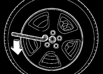
(cid:84) Braking when a tire is punctured Do not depress the brake pedal suddenly when a tire is punctured. This could cause a loss of control of the vehicle. Keep driving straight ahead while gradually reducing speed. Then slowly pull off the road to a safe place.
(cid:132) Brake system (cid:84) Two separate circuits Your vehicle has a dual circuit brake systems. Each circuit works diagonally across the vehicle. If one cir- cuit of the brake system should fail, the other half of the system still works. If one circuit fails, the brake pedal will go down much closer to the floor than usual and you will need to press it down much harder. And a much longer distance will be needed to stop the vehi- cle. (cid:84) Brake booster The brake booster uses engine manifold vacuum to assist braking force. Do not turn off the engine while driving because that will turn off the brake booster, re- sulting in poor braking power. The brakes will continue to work even when the brake booster completely stops functioning. If this happens, however, you will have to push the pedal much harder
than normal and the braking distance will increase.
ABS (Anti-lock Brake System)
Starting and operating
(cid:132) Disc brake pad wear warning indica-
tors
HS7012BA
The disc brake pad wear warning indicators on the disc brakes give a warning noise when the brake pads are worn. If a squeaking or scraping noise is heard from the disc brakes while braking, immediately have your vehicle inspected by the nearest SUBARU dealer.
Always use the utmost care in driving – over- confidence because you are driving with an ABS equipped vehicle could easily lead to a se- rious accident.
(cid:121) The ABS system does not always decrease stopping distance. You should always maintain a safe following distance from other vehicles. (cid:121) When driving on badly surfaced roads, gravel roads, icy road, or over deep newly fallen snow, stopping distances may be longer for a vehicle with the ABS system than one without. When driving under these conditions, therefore, re- duce your speed and leave ample distance from other vehicles. (cid:121) When you feel the ABS system operating, you should maintain constant brake pedal pres- sure. Do not pump the brake pedal since doing so may defeat the operation of the ABS system.
– CONTINUED – 7-33
Starting and operating
The ABS system prevents the lock-up of wheels which may occur during sudden braking or braking on slip- pery road surfaces. This helps prevent the loss of steering control and directional stability caused by wheel lock-up. When the ABS system is operating, you may hear a chattering noise or feel a slight vibration in the brake pedal. This is normal when the ABS operates. The ABS system will not operate when the vehicle speed is below approximately 6 mph (10 km/h).
(cid:132) ABS system self-check You may feel a slight shock in the brake pedal and hear the operating sound of ABS from the engine com- partment just after the vehicle is started. This is caused by an automatic functional test of the ABS sys- tem being carried out and does not indicate any abnor- mal condition.
7-34
(cid:132) ABS warning light
UB4010GA
The ABS warning light comes on when the ignition switch is turned to the “ON” position and goes out after about two seconds. This is an indication that the ABS system is working properly.
If the warning light behaves as follows, the ABS system may not be working properly. When the warning light is on, the ABS function shuts down; however, the conventional brake system continues to operate normally.
(cid:121) The warning light does not come on when the ignition switch is turned to the “ON” position. (cid:121) The warning light comes on when the ignition switch is turned to the “ON” position, but it does not go out even when the vehicle speed exceeds approximately 8 mph (12 km/h). (cid:121) The warning light comes on during driving. If these occur, have the ABS system repaired at the first available opportunity by your SUBARU dealer.
NOTE If the warning light behavior is as described be- low, the ABS system may be considered normal. (cid:121) The warning light comes on right after the en- gine is started but goes out immediately, remain- ing off. (cid:121) The warning light remains on after the engine has been started, but it goes out when the vehicle speed reaches about 8 mph (12 km/h). (cid:121) The warning light comes on during driving, but it goes out immediately and remains off. When driving with an insufficient battery voltage such as when the engine is jump started, the ABS warning light may come on. This is due to the low battery volt- age and does not indicate a malfunction. When the
Starting and operating
battery becomes fully charged, the light will go out.
– CONTINUED – 7-35
Starting and operating
Parking your vehicle
(cid:121) Never leave unattended children or pets in the vehicle. They could accidentally injure themselves or others through inadvertent oper- ation of the vehicle. Also, on hot or sunny days, the temperature in a closed vehicle could quickly become high enough to cause severe or possibly fatal injuries to them. (cid:121) Do not park the vehicle over flammable mate- rials such as dry grass, waste paper or rags, as they may burn easily if they come near hot en- gine or exhaust system parts. (cid:121) Be sure to stop the engine if you take a nap in the vehicle. If engine exhaust gas enters the passenger compartment, occupants in the ve- hicle could die from carbon monoxide (CO) contained in the exhaust gas.
Never drive while the parking brake is set be- cause this will cause unnecessary wear on the brake linings. Before starting to drive, always
7-36
make sure that the parking brake has been fully released.
To set the parking brake, press the brake pedal firmly and hold it down while fully pulling up the parking brake lever.
UB4001BA
To release the parking brake, pull the lever up slightly, press the release button, then lower the lever while keeping the button pressed. When the parking brake is set while the engine is run- ning, the parking brake warning light comes on. After starting the vehicle, be sure that the warning light has gone out before the vehicle is driven. Refer to the
“Warning and indicator lights” section (chapter 3). When parking your vehicle, always set the parking brake firmly and put the shift lever in the “1” (1st) for an upgrade or “R” (Reverse) for a downgrade for manual transmission vehicles, or in the “P” (Park) position for automatic transmission vehicles. Always set the park- ing brake firmly when parking your vehicle. Never rely on the transmission alone to hold the vehicle.
When parking on a hill, always turn the steering wheel. When the vehicle is headed up the hill, the front wheels should be turned away from the curb.
UB7033AA
Starting and operating
When facing downhill, the front wheels should be turned into the curb.
UB7032AA
– CONTINUED – 7-37
Starting and operating
Cruise control
Do not use the cruise control under any of the following conditions. This may cause loss of vehicle control: (cid:121) driving up or down a steep grade (cid:121) driving on slippery or winding roads (cid:121) driving in heavy traffic
Cruise control enables you to maintain a constant ve- hicle speed without holding your foot on the accelera- tor pedal and it is operative when the vehicle speed is 25 mph (40 km/h) or more. Make sure the main switch is turned “OFF” when the cruise control is not in use to avoid unintentionally by setting the cruise control.
7-38
(cid:132) To set cruise control
UB7038BA
ACC RES
CANCELSETCOAST
HS7018BA
1. Push the “CRUISE” main switch. The indicator light on the switch will come on. 2. Depress the accelerator pedal until the vehicle reaches the desired speed. 3. Push the control lever downward in the “SET, COAST” direction and release it. Then release the ac- celerator pedal. The vehicle will maintain the desired speed.
UB4010KA
” indicator light is illuminated in
At this time, the “ the combination meter. Vehicle speed can be temporarily increased while driving with the cruise control activated. Simply de- press the accelerator pedal to accelerate the vehicle.
Starting and operating
When the accelerator pedal is released, the vehicle will return to and maintain the previous cruising speed.
(cid:132) To temporarily cancel the cruise con-
trol
There are four ways to cancel the cruise control tem- porarily: (cid:121) Depress the brake pedal. (cid:121) Pull the control lever in the “CANCEL” direction. (if so equipped) (cid:121) Depress the clutch pedal (manual transmission ve- hicles only). (cid:121) Shift the selector lever into the “N” position (auto- matic transmission vehicles only). (cid:121) Shift the shift lever into neutral position (manual transmission vehicles only). The “ goes off when the cruise control is cancelled. To resume the cruise control after it has been tempo- rarily canceled and with vehicle speed of about 20
mph (32 km/h) or more, push the control lever upward in the “ACCEL, RESUME” direction to return to the original cruising speed automatically. The “ will automatically come on at this time.” indicator light in the combination meter
” indicator light in the combination meter
– CONTINUED – 7-39
Starting and operating
(cid:132) To turn off the cruise control There are two ways to turn off the cruise control: (cid:121) Push the main switch again. (cid:121) Turn the ignition switch to the “ACC” position (but only when the vehicle is completely stopped).
(cid:132) To change the cruising speed (cid:84) To increase the speed (by control lever) Push the control lever upward in the “ACCEL, RE- SUME” direction and hold it until the vehicle reaches the desired speed. Then, release the control lever. The vehicle speed at that moment will be memorized and treated as the new set speed. When the difference between the actual vehicle speed and the set speed is less than 4 mph (6.8 km/h), the set speed can be increased 1 mph (1.6 km/h) each time by pressing the control lever upward in the “AC- CEL, RESUME” direction quickly. (cid:84) To increase the speed (by accelerator pedal) 1. Depress the accelerator pedal to accelerate the ve- hicle to the desired speed. 2. Push the control lever downward in the “SET, COAST” direction once. Now the desired speed is set and the vehicle will keep running at that speed without
7-40
depressing the accelerator pedal. NOTE If the difference between the actual vehicle speed when the control lever is pushed downward and the speed last time you set it is less than 4 mph (6.8 km/h), the vehicle speed will be lowered by 1
mph (1.6 km/h). This occurs because the cruise control system unit regards this lever operation as