- Download PDF Manual
-
position.
● Locking the doors with the remote controller. ● Switching the room light switch in the OFF
position.
3. Press the
button again within 1 min-
ute to unlock all doors and the rear hatch.
Pre-driving checks and adjustments 3-19
The panic alarm stops when: ● It has run for a period of time, or ● Any button is pressed on the Intelligent Key. ● The request switch on the driver or passen- ger door or rear hatch has been pushed and the Intelligent Key is in range of the door handle.
WPD0374
Using the panic alarm If you are near your vehicle and feel threatened, you may activate the panic alarm to call attention button on the by pressing and holding the Intelligent Key for longer than 0.5 seconds. The panic alarm and headlights will stay on for a period of time.
3-20 Pre-driving checks and adjustments
WPD0362
Silencing the horn beep feature If desired, the horn beep feature can be deacti- vated using the Intelligent Key.
To deactivate: Press and hold the and
buttons for at least 2 seconds.
The hazard warning lights will flash 3 times to confirm that the horn beep feature has been deactivated.
To activate: Press and hold the and more.
buttons for at least 2 seconds once
The hazard warning lights will flash once and the horn will sound once to confirm that the horn beep feature has been reactivated. Deactivating the horn beep feature does not si- lence the horn if the alarm is triggered.
䊊1
LPD2094
P (Park) position selecting warning light (if so equipped) NISSAN Intelligent Key® warning light
䊊2
WARNING LIGHTS AND AUDIBLE REMINDERS The Intelligent Key is equipped with a function that is designed to minimize improper operations and to help prevent the vehicle from being stolen. The warning buzzer sounds and the warning light illuminates when improper operations are de- tected.CAUTION
When the buzzer sounds and the warning light illuminates, be sure to check both the vehicle and the Intelligent Key. WARNING SIGNALS To help prevent the vehicle from moving unex- pectedly by erroneous operation of the Intelligent Key or to help prevent the vehicle from being stolen, a chime or buzzer sounds from inside and outside the vehicle and a warning is displayed in the instrument panel. When a chime or beep sounds or a warning is displayed, be sure to check the vehicle and the Intelligent Key. See the “Troubleshooting guide” that follows and “Warning/indicator lights and audible reminders” in the “Instruments and controls” section of this manual.
Pre-driving checks and adjustments 3-21
Audible reminder and warning when locking the doors When the chime or buzzer sounds from inside and outside the vehicle, check for the following: ● The ignition switch is placed in the LOCK
position.
● The Intelligent Key is not left inside the ve-
hicle.
● The shift lever is in the P (Park) position. Audible reminder and warning when the engine stops When the P position selecting warning light
) in the instrument panel illuminates red:
● Make sure the shift lever is in the P (Park)
position.
When the chime sounds intermittently: ● Make sure the shift lever is in the P (Park) position and the ignition switch is placed in the LOCK position.
3-22 Pre-driving checks and adjustments
If the chime sounds continuously when the driv- er’s door is opened, check the following: ● The shift lever is placed in the P (Park) position and the ignition switch is placed in the LOCK position.
● The warning chime may stop when one of
the following is performed:
– Returning the ignition switch to the LOCK
NISSAN recommends replacing the battery at a NISSAN dealer. Preventing the Intelligent Key from being left in the vehicle If you lock all doors using the power door lock switch with the Intelligent Key in the vehicle, all of the doors unlock immediately and the buzzer will warn you when the door is closed.
position.
– Closing the doors.
Alarm and warning when the engine starts When the Intelligent Key system warning light ) blinks red and the outside buzzer sounds, make sure the Intelligent Key is inside the vehicle. Warning for low battery power When the Intelligent Key battery is low, the Intel- ) will blink ligent Key system warning light ( green for about 30 seconds after the ignition switch is placed in the ON position. This warning is to let you know that the battery of the Intelligent Key will run down soon. Replace it with a new one. Refer to “Battery replacement” in the “Main- tenance and do-it-yourself” section.
TROUBLESHOOTING GUIDE
When pushing the ignition switch to stop the engine
The P (Park) warning light in the instrument panel illuminates and the inside chime sounds continuously.
Symptom
Possible Cause
Remedy
The shift lever is not in the P (Park) position. Make sure that the shift lever is in the P
(Park) position.
When opening the driver’s door
A warning chime sounds continuously.
The ignition switch is in the “ACC” position.
When pushing the door handle request switch to lock the door
When closing the doors
When stopping the engine
When starting the engine
The outside chime sounds for approximately a few seconds. The key warning light in the instrument panel blinks, the outside chime sounds 3
times and the inside warning chime sounds for approximately 3 seconds. The P (Park) warning light in the instrument panel illuminates and the outside chime sounds continuously. The outside chime sounds for approximately 3 seconds and all doors unlock. The P (Park) position warning light in the instrument panel blinks in red.The key warning light in the instrument panel blinks in green.
The battery charge is low.
When pushing the LOCK button on the Intelligent Key to lock the door
The outside chime sounds for a few sec- onds and all the doors unlock.
A door is not closed securely.
The Intelligent Key is inside the vehicle. A door is not closed securely. The ignition switch is in the “ACC” or “ON” position.
Place the ignition switch in the “OFF” position. Be sure to carry the Intelligent Key with you. Close the door securely. Place the ignition switch in the “OFF” position.
The ignition switch is in the “ACC” or “OFF” position and the shift lever is not in the P (Park) position. The Intelligent Key is in the vehicle.
Make sure that the shift lever is in the P (Park) position and place the ignition switch in the “OFF” position. Be sure to carry the Intelligent Key with you.
The shift lever is not in the P (Park) position. Make sure that the shift lever is in the P
(Park) position and place the ignition switch in the LOCK position. Replace the battery with a new one. See “Battery replacement” in the “Maintenance and do-it-yourself” section. Close the door securely.
Pre-driving checks and adjustments 3-23
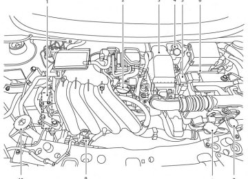
HOOD
WARNING
● Make sure the hood is completely closed and latched before driving. Fail- ure to do so could cause the hood to fly open and result in an accident.
● If you see steam or smoke coming from the engine compartment, to avoid injury do not open the hood.
1. Pull the hood lock release handle 䊊1 located below the instrument panel until the hood springs up slightly.
2. Locate the lever 䊊2 in between the hood and grille and push the lever sideways with your fingertips.
3. Raise the hood 䊊3 . 4. Remove the support rod 䊊4 and insert it into
the slot 䊊5 .
LPD2169
Hold the coated parts 䊊A when removing or resetting the support rod. Avoid direct con- tact with the metal parts, as they may be hot immediately after the engine has been stopped.When closing the hood, return the support rod to its original position, lower the hood to approxi- mately 12 in (30 cm) above the latch and release it. This allows proper engagement of the hood latch.
3-24 Pre-driving checks and adjustments
REAR HATCH
WARNING
The rear hatch must be closed securely before driving. An open rear hatch could allow dangerous exhaust gases to be drawn inside the vehicle. See “Exhaust gas (carbon monoxide)” in the “Starting and driving” section of this manual.
● Press the
button on the Intelligent Key (if equipped) twice. See “NISSAN Intelligent Key®” in this section.
LPD2170
OPENING THE REAR HATCH To open the rear hatch, unlock it with one of the following operations, then pull the handle. ● Push the power door lock switch to the
unlock position.
● Unlock all doors using the key.
● Press the
button on the keyfob (if equipped) twice. See “Remote keyless entry system” in this section.
● Push the rear hatch request switch or door handle request switch (if equipped) twice. See “NISSAN Intelligent Key®” in this sec- tion.
Pre-driving checks and adjustments 3-25
FUEL-FILLER DOOR
3. Push the rear hatch up to open.
NOTE: If you had to open the rear hatch using this lever, have your vehicle checked by a NISSAN dealer as soon as possible.
LPD2022
OPENER OPERATION The fuel-filler door release is located below the instrument panel. To open the fuel-filler door, pull the release. To lock, close the fuel-filler door securely.
LPD2171
REAR HATCH RELEASE The rear hatch release mechanism allows the rear hatch to be opened in the event of a discharged battery.
To release the rear hatch from the inside of the vehicle, perform the following operations:
1. Fold the rear seats down. See “Folding rear seat” in the “Safety — seats, seat belts and supplemental restraint system” section of this manual.
2.
Insert a suitable tool in the access opening. Move the release lever to the right. The rear hatch will be unlatched.
3-26 Pre-driving checks and adjustments
FUEL-FILLER CAP
WARNING
● Gasoline is extremely flammable and highly explosive under certain condi- tions. You could be burned or seriously injured if it is misused or mishandled. Always stop the engine and do not smoke or allow open flames or sparks near the vehicle when refueling.
● Do not attempt to top off the fuel tank after the fuel pump nozzle shuts off automatically. Continued refueling may cause fuel overflow, resulting in fuel spray and possibly a fire.
● Use only an original equipment type fuel-filler cap as a replacement. It has a built-in safety valve needed for proper operation of the fuel system and emis- sion control system. An incorrect cap can result in a serious malfunction and possible injury. It could also cause Malfunction Indicator Light the (MIL) to come on.
● Never pour fuel into the throttle body to
attempt to start your vehicle.
● Do not fill a portable fuel container in the vehicle or trailer. Static electricity can cause an explosion of flammable liquid, vapor or gas in any vehicle or trailer. To reduce the risk of serious injury or death when filling portable fuel containers: – Always place the container on the
ground when filling.
– Do not use electronic devices when
filling.
– Keep the pump nozzle in contact with the container while you are fill- ing it.
– Use only approved portable fuel con-
tainers for flammable liquid.
CAUTION
● Do not use E-15 or E-85 fuel in your vehicle. For further information see the “Fuel Recommendation” in the “Techni- cal and consumer information” section of this manual.
● The LOOSE FUEL CAP warning mes- sage will be displayed if the fuel-filler cap is not properly tightened. It may take a few driving trips for the message to be displayed. Failure to tighten the fuel-filler cap properly after the LOOSE FUEL CAP warning message is dis- Malfunc- played may cause the tion Indicator Light (MIL) to illuminate. ● Failure to tighten the fuel-filler cap Malfunc- properly may cause the tion Indicator Light (MIL) to illuminate. light illuminates because If the the fuel-filler cap is loose or missing, tighten or install the cap and continue light to drive the vehicle. The should turn off after a few driving trips. light does not turn off after a If the few driving trips, have the vehicle in- spected by a NISSAN dealer.
● For additional
information, see the “Malfunction Indicator Light (MIL)” in the “Instruments and Controls” section in this manual.
● If fuel is spilled on the vehicle body, flush it away with water to avoid paint damage.
Pre-driving checks and adjustments 3-27
3. Push the loose fuel cap warning reset button 䊊A in the meter for about 1 second to turn off the LOOSE FUEL CAP warning message after tightening the fuel-filler cap.
LPD2172
LPD2025
To remove the fuel-filler cap: 1. Turn the fuel-filler cap counterclockwise to
remove.
2. Put the fuel-filler cap on the cap holder 䊊1
while refueling.
To install the fuel-filler cap: 1.
Insert the fuel-filler cap straight into the fuel- filler tube.
2. Turn the fuel-filler cap clockwise until a
single click is heard.
Loose Fuel Cap warning message The LOOSE FUEL CAP warning message dis- plays in the odometer when the fuel-filler cap is not tightened correctly after the vehicle has been refueled. It may take a few driving trips for the message to be displayed. To turn off the warning message, perform the following: 1. Remove and install the fuel-filler cap as pre-
viously described as soon as possible. 2. Tighten the fuel-filler cap until it clicks.
3-28 Pre-driving checks and adjustments
STEERING WHEEL
SUN VISORS
䊊3 Slide the extension sun visor in or out as
needed.
CAUTION
● Do not store the sun visor before return- ing the extension to its original position.
● Do not pull the extension sun visor forc-
ibly downward.
LPD0355
TILT OPERATION Push the lock lever 䊊1 down and adjust the steering wheel up or down 䊊2 to the desired position. Pull the lock lever 䊊1 up to lock the steering wheel in place.
WARNING
Do not adjust the steering wheel while driving. You could lose control of your vehicle and cause an accident.
WPD0435
䊊1 To block glare from the front, swing down thesun visor.
䊊2 To block glare from the side, remove the sun visor from the center mount and swing the visor to the side.
Pre-driving checks and adjustments 3-29
MIRRORS
LPD0481
WPD0126
LPD0237
VANITY MIRRORS (if so equipped) To access the vanity mirror, pull the sun visor down and slide the mirror cover open. Some vanity mirrors are illuminated and turn on when the mirror cover is open.
REARVIEW MIRROR The night position 䊊1 reduces glare from the headlights of vehicles behind you at night. Use the day position 䊊2 when driving in daylight hours.
WARNING
Use the night position only when neces- sary, because it reduces rear view clarity.
OUTSIDE MIRRORS
WARNING
● Do not adjust the mirrors while driving. You could lose control of your vehicle and cause an accident.
● Objects viewed in the outside mirror on the passenger side are closer than they appear. Be careful when moving to the right. Using only this mirror could cause an accident. Use the inside mirror or glance over your shoulder to properly judge distances to other objects.
3-30 Pre-driving checks and adjustments
The outside mirror remote control only operates when the ignition switch is placed in the ACC or ON position. Move the small switch 䊊1 to select the right or left mirror. Adjust each mirror to the desired position using the large switch 䊊2 .
LPD0259
Manual folding outside mirrors Pull the outside mirror toward the door to fold it. Heated mirrors (if so equipped) Some outside mirrors can be heated to defrost, defog, or de-ice for improved visibility. For addi- tional information, see “Rear window and outside mirror defroster switch” in the “Instruments and controls” section of this manual.
Pre-driving checks and adjustments 3-31
4 Monitor, climate, audio, phone and voice recognition systems
Control panel buttons — color screen with Navigation System (if so equipped) . . . . . . . . . . . . . . . . . . 4-2
How to use the touch screen . . . . . . . . . . . . . . . . . . . . 4-3
How to use the BACK button . . . . . . . . . . . . . . . . . . . . 4-5
How to use the MENU button . . . . . . . . . . . . . . . . . . . . 4-5
button. . . . . . . . . . . . . . . . . . . . . . . . . . . . . . . . . . . 4-9
RearView Monitor (if so equipped). . . . . . . . . . . . . . . . . . . 4-9
How to read the displayed lines . . . . . . . . . . . . . . . . . 4-10
Difference between predicted and actual distances . . . . . . . . . . . . . . . . . . . . . . . . . . . . . . . . . . . . . 4-11
Adjusting the screen . . . . . . . . . . . . . . . . . . . . . . . . . . . 4-13
Operating tips. . . . . . . . . . . . . . . . . . . . . . . . . . . . . . . . . 4-14
Around View® Monitor (if so equipped) . . . . . . . . . . . . . 4-15
Available views . . . . . . . . . . . . . . . . . . . . . . . . . . . . . . . . 4-16
How to switch the display . . . . . . . . . . . . . . . . . . . . . . 4-19
How to adjust the screen view . . . . . . . . . . . . . . . . . . 4-19
View malfunction . . . . . . . . . . . . . . . . . . . . . . . . . . . . . . 4-19
Operating tips. . . . . . . . . . . . . . . . . . . . . . . . . . . . . . . . . 4-20
Vents . . . . . . . . . . . . . . . . . . . . . . . . . . . . . . . . . . . . . . . . . . . 4-20
Heater and Air Conditioner (manual) . . . . . . . . . . . . . . . . 4-21
Controls . . . . . . . . . . . . . . . . . . . . . . . . . . . . . . . . . . . . . . 4-22
Heater operation . . . . . . . . . . . . . . . . . . . . . . . . . . . . . . 4-23
Air conditioner operation (if so equipped) . . . . . . . . 4-24Air flow charts. . . . . . . . . . . . . . . . . . . . . . . . . . . . . . . . . 4-25
Servicing air conditioner (if so equipped) . . . . . . . . . . . . 4-29
Audio system . . . . . . . . . . . . . . . . . . . . . . . . . . . . . . . . . . . . 4-29
Radio . . . . . . . . . . . . . . . . . . . . . . . . . . . . . . . . . . . . . . . . 4-29
FM radio reception . . . . . . . . . . . . . . . . . . . . . . . . . . . . 4-29
AM radio reception . . . . . . . . . . . . . . . . . . . . . . . . . . . . 4-30
Satellite radio reception (if so equipped) . . . . . . . . . 4-30
Audio operation precautions . . . . . . . . . . . . . . . . . . . . 4-30
FM/AM radio with compact disc (CD) player (if so equipped) . . . . . . . . . . . . . . . . . . . . . . . . . . . . . . . 4-37
FM/AM/SAT radio with compact disc (CD) player (Type A) (if so equipped) . . . . . . . . . . . . . . . . . 4-42
FM/AM/SAT radio with compact disc (CD) player (Type B) (if so equipped) . . . . . . . . . . . . . . . . . 4-47
USB interface (models without Navigation System) (if so equipped) . . . . . . . . . . . . . . . . . . . . . . . 4-53
USB interface (models with Navigation System) . . . . . . . . . . . . . . . . . . . . . . . . . . . . . . . . . . . . . . 4-55
iPod®* player operation without Navigation System (if so equipped) . . . . . . . . . . . . . . . . . . . . . . . . 4-57
iPod®* player operation with Navigation System (if so equipped) . . . . . . . . . . . . . . . . . . . . . . . . 4-59
Bluetooth® streaming audio without Navigation System (if so equipped) . . . . . . . . . . . . . . 4-62Bluetooth® streaming audio with Navigation System (if so equipped) . . . . . . . . . . . . . . . . . . . . . . . . 4-63
Pandora® audio (if so equipped) . . . . . . . . . . . . . . . . 4-65
CD care and cleaning . . . . . . . . . . . . . . . . . . . . . . . . . . 4-66
Steering wheel switch for audio control (if so equipped) . . . . . . . . . . . . . . . . . . . . . . . . . . . . . . . 4-67
Antenna . . . . . . . . . . . . . . . . . . . . . . . . . . . . . . . . . . . . . . 4-68
Car phone or CB radio . . . . . . . . . . . . . . . . . . . . . . . . . . . . 4-68
Bluetooth® Hands-Free Phone System without Navigation System (if so equipped) . . . . . . . . . . . . . . . . . 4-69
Regulatory Information . . . . . . . . . . . . . . . . . . . . . . . . . 4-71
Using the system . . . . . . . . . . . . . . . . . . . . . . . . . . . . . . 4-71
Control buttons . . . . . . . . . . . . . . . . . . . . . . . . . . . . . . . 4-74
Getting started . . . . . . . . . . . . . . . . . . . . . . . . . . . . . . . . 4-74
List of voice commands . . . . . . . . . . . . . . . . . . . . . . . . 4-76
Voice Adaptation (VA) mode . . . . . . . . . . . . . . . . . . . . 4-80
Manual control . . . . . . . . . . . . . . . . . . . . . . . . . . . . . . . . 4-82
Troubleshooting guide . . . . . . . . . . . . . . . . . . . . . . . . . 4-83Bluetooth® Hands-Free Phone System with Navigation System (if so equipped) . . . . . . . . . . . . . . . . . 4-84
Regulatory Information . . . . . . . . . . . . . . . . . . . . . . . . . 4-85Voice commands . . . . . . . . . . . . . . . . . . . . . . . . . . . . . . 4-86
Connecting procedure . . . . . . . . . . . . . . . . . . . . . . . . . 4-86
Vehicle phonebook . . . . . . . . . . . . . . . . . . . . . . . . . . . . 4-87
Making a call. . . . . . . . . . . . . . . . . . . . . . . . . . . . . . . . . . 4-88
Receiving a call . . . . . . . . . . . . . . . . . . . . . . . . . . . . . . . 4-89
During a call . . . . . . . . . . . . . . . . . . . . . . . . . . . . . . . . . . 4-89
Ending a call . . . . . . . . . . . . . . . . . . . . . . . . . . . . . . . . . . 4-89
Text messaging. . . . . . . . . . . . . . . . . . . . . . . . . . . . . . . . 4-90
Bluetooth settings . . . . . . . . . . . . . . . . . . . . . . . . . . . . . 4-91
Phone settings . . . . . . . . . . . . . . . . . . . . . . . . . . . . . . . . 4-93NISSAN Voice Recognition System (if so equipped) . . . . . . . . . . . . . . . . . . . . . . . . . . . . . . . . . . 4-94
Using the system . . . . . . . . . . . . . . . . . . . . . . . . . . . . . . 4-94
System features . . . . . . . . . . . . . . . . . . . . . . . . . . . . . . . 4-95
Bluetooth® Hands-Free Phone System voice commands . . . . . . . . . . . . . . . . . . . . . . . . . . . . . . 4-96
Navigation System voice commands . . . . . . . . . . . . . 4-97
Audio system voice commands. . . . . . . . . . . . . . . . . . 4-97
Information voice commands. . . . . . . . . . . . . . . . . . . . 4-98
Help voice commands . . . . . . . . . . . . . . . . . . . . . . . . . 4-98
Troubleshooting guide . . . . . . . . . . . . . . . . . . . . . . . . . 4-99WARNING
● Positioning of the heating or air condi- tioning controls and display controls should not be done while driving in or- der that full attention may be given to the driving operation.
● Do not disassemble or modify this sys- tem. If you do, it may result in accidents, fire, or electrical shock.
● Do not use this system if you notice any abnormality, such as a frozen screen or lack of sound. Continued use of the system may result in accident, fire or electric shock.
● In case you notice any foreign object in the system hardware, spill liquid on it, or notice smoke or smell coming from it, stop using the system immediately and contact your nearest NISSAN dealer. Ig- noring such conditions may lead to ac- cidents, fire or electrical shock.
CONTROL PANEL BUTTONS — COLOR SCREEN WITH NAVIGATION SYSTEM (if so equipped)
1. Display screen
button**
2. 3. MAP button*
4. NAV button*
LHA2516
5. MENU button
6. BACK button
7. TUNE knob / AUDIO button
8.
(brightness control) button
4-2 Monitor, climate, audio, phone and voice recognition systems
WARNING
● ALWAYS give your full attention to
driving.
● Avoid using vehicle features that could distract you. If distracted, you could lose control of your vehicle and cause an accident.
9. On-Off button/VOL (volume) control knob
10. CAMERA button
HOW TO USE THE TOUCH SCREEN
* For information regarding the Navigation system control buttons, refer to the separate Navigation System Owner’s Manual.
information regarding the Bluetooth® ** For Hands-Free Phone System control button, see “Bluetooth® Hands-Free Phone System” in this section.
When you use this system, make sure the engine is running. If you use the system with the engine not running (ignition ON or ACC) for a long time, it will discharge the battery, and the engine will not start.
Reference symbols:
“Example” — Words marked in quotes refer to a key shown only on the display. These keys can be selected by touching the screen.
CAUTION
● The glass display screen may break if it is hit with a hard or sharp object. If the glass screen breaks, do not touch it. Doing so could result in an injury.
● To clean the display, never use a rough cloth, alcohol, benzine, thinner or any kind of solvent or paper towel with a chemical cleaning agent. They will scratch or deteriorate the panel.
● Do not splash any liquid such as water or car fragrance on the display. Contact with liquid will cause the system to malfunction.
To help ensure safe driving, some functions can- not be operated while driving.
The on-screen functions that are not available while driving will be “grayed out” or muted.
Park the vehicle in a safe location and then oper- ate the navigation system.
Monitor, climate, audio, phone and voice recognition systems 4-3
LHA2245
LHA2246
Touch screen operation Selecting the item: Touch an item to select. For example, to select the “Audio” key, touch the “Audio” key 䊊1 on the screen.
Adjusting the item: For screens where an item can be adjusted incre- mentally, such as when adjusting the bass and treble for the audio system, touch the “+” key 䊊1
or the “⫺” key 䊊2 to adjust the settings of an item. When there are more items than can be dis- played on one screen, touch the up arrow 䊊3 to scroll up the page or touch the down arrow 䊊4 to scroll down the page.LHA1478
Other items are adjusted by selecting one of a set number of conditions. For example, the Display Mode can be set to “Automatic”, “Day” or “Night”. To adjust this type of item, touch the item 䊊1 . The item will cycle through the available settings and the red indicator lights to the left of the setting condition 䊊2 will come on or turn off accordingly.4-4 Monitor, climate, audio, phone and voice recognition systems
● OK:
Completes the character input.
Touch screen maintenance If you clean the display screen, use a dry, soft cloth. If additional cleaning is necessary, use a small amount of neutral detergent with a soft cloth. Never spray the screen with water or de- tergent. Dampen the cloth first and then wipe the screen. HOW TO USE THE BACK BUTTON Press the BACK button to return to the previous screen.
LHA2253
HOW TO USE THE MENU BUTTON For more information about the “POIs Powered by Google™”, “Google™ Send-To-Car, “Traffic Information” and “Weather” features, see the separate Navigation System Owner’s Manual. For more information about the “Voice Com- mands” key, see “NISSAN Voice Recognition System” in this section. To select and/or adjust several functions, fea- tures and modes that are available for your ve- hicle: 1. Press the MENU button. 2. Select the “Settings” key.Monitor, climate, audio, phone and voice recognition systems 4-5
LHA2247
Inputting characters: Touch the letter key 䊊1 . There are some options available when inputting characters. ● 123 / ABC:
Changes the available character set to num- bers.
● Space:
Inserts a space.
● Delete:
Deletes the last inputted character with one touch. Touch and hold the “Delete” key to delete all of the characters.
Phone & Bluetooth information regarding the Bluetooth® For Hands-Free Phone System, see “Bluetooth® Hands-Free Phone System” in this section. For information regarding Bluetooth® audio, see “Bluetooth® streaming audio with Navigation System” in this section.
LHA2248
3. Select the desired item. Audio For audio setup, refer to “Audio system” in this section. Navigation Refer to the separate Navigation System Own- er’s Manual for information regarding this item.
LHA2249
System Select the “System” key to select and/or adjust various functions of the system. A screen with additional options will appear.
4-6 Monitor, climate, audio, phone and voice recognition systems
Display Mode The display can be adjusted to fit the level of lighting in the vehicle. Touch the “Display Mode” key to cycle through the options. “Day” and “Night” modes are suited for the respective times of day, while “Automatic” controls the display automatically. Scroll Direction The direction that menus scroll can be adjusted. Choose either “up” or “down”.
LHA1482
Display: Select the “Display” key to adjust the appearance of the display. The following settings can be adjusted: Brightness The brightness of the display can be set to Very Bright, Bright, Default, Dark or Very Dark. Touch the “Brightness” key to cycle through the options.
LHA2250
Clock Settings: Select the “Clock Settings” key to adjust the time and the appearance of the clock on the display. The following settings can be adjusted: Time Format The clock can be set to 12 hours or 24 hours. Date Format Select from five possible formats of displaying the day, month and year.
Monitor, climate, audio, phone and voice recognition systems 4-7
Clock Mode Select the mode for the clock. “Auto” uses the system’s GPS to automatically maintain the time. “Manual” allows you to set the clock using the “Set Clock Manually” key. “Time Zone” maintains the time based upon the zone selected when selecting the “Time Zone” key.
LHA2251
LHA2252
Set Clock Manually When this setting is activated, the clock can be set manually. Touch the “+” or “-” keys to adjust the hours, minutes, day, month and year up or down. “Clock Mode” must be set to “Manual” for this option to be available. Daylight Savings Time When this setting is activated, daylight savings time is on. Touch the “Daylight Savings Time” key to toggle the setting on or off. Time Zone Choose the applicable time zone from the list.
Language:
Select the “Language” key to adjust the language used by the system. The language can be set to English, Français or Español. Touchscreen click:
Select the “Touchscreen Click” key to toggle the touchscreen click feature on or off. When acti- vated, a click sound will be heard every time a key on the screen is touched. System Beeps: Select the “System Beeps” key to toggle the system beep tones feature on or off. When acti- vated, a beep sound will be heard when a pop-up
4-8 Monitor, climate, audio, phone and voice recognition systems
message appears on the screen or a button on the unit (such as the button) is pressed and held for two seconds. Reset all settings/memory: Select the “Reset All Settings/Memory” key to return all settings to default and to clear the memory. Info For information about the “Info” key, see the separate Navigation System Owner’s Manual. XM For XM setup, refer to “Audio system” in this section.
BUTTON
To change the display brightness, press the button. Pressing the button again will change the display to the day or the night display. If no operation is performed within 5 seconds, the display will return to the previous display.
button for more than Press and hold the two seconds to turn the display off. Press the button again to turn the display on.
REARVIEW MONITOR (if so equipped)
When the shift lever is shifted into the R (Re- verse) position, the monitor display shows a rear- ward view from the vehicle.
WARNING
Failure to follow the warnings and instruc- tions for proper use of the RearView Monitor could result in serious injury or death. ● The RearView Monitor is a convenience but it is not a substitute for proper back- ing. Always turn and look out the win- dows, and check mirrors to be sure that it is safe to move before operating the vehicle. Always back up slowly.
● The system is designed as an aid to the driver in showing large stationary ob- jects directly behind the vehicle, to help avoid damaging the vehicle.
● The system cannot completely elimi- nate blind spots and may not show ev- ery object.
● Underneath the bumper and the corner areas of the bumper cannot be viewed on the RearView Monitor because of its monitoring range limitation. The system will not show small objects below the bumper, and may not show objects close to the bumper or on the ground. ● Objects viewed in the RearView Moni- tor differ from actual distance because a wide-angle lens is used.
● Objects in the RearView Monitor will appear visually opposite than when viewed in the rear view and outside mirrors.
● When washing the vehicle with high- pressure water, be sure not to spray it around the camera. Otherwise, water may enter the camera unit causing wa- ter condensation on the lens, a mal- function, fire or an electric shock.
● Make sure that the hatch is securely
closed when backing up.
● Do not put anything on the rearview camera. The rearview camera is in- stalled on top of the hatch.
Monitor, climate, audio, phone and voice recognition systems 4-9
● When washing the vehicle with high pressure water, be sure not to spray it around the camera. Otherwise, water may enter the camera unit causing wa- ter condensation on the lens, a mal- function, fire or an electric shock.
● Do not strike the camera. It is a preci- sion instrument. Otherwise, it may mal- function or cause damage resulting in a fire or an electric shock.
CAUTION
There is a plastic cover over the camera. Do not scratch the cover when cleaning dirt or snow from the cover.
LHA0437
HOW TO READ THE DISPLAYED LINES Guiding lines which indicate the vehicle width and distances to objects with reference to the vehicle body line 䊊A are displayed on the monitor. Distance guide lines: Indicate distances from the vehicle body. ● Red line 䊊1 : approx. 1.5 ft (0.5 m) ● Yellow line 䊊2 : approx. 3 ft (1 m) ● Green line 䊊3 : approx. 7 ft (2 m) ● Green line 䊊4 : approx. 10 ft (3 m)
LHA2278
The on-screen guidelines can be set to on or off. With the shift lever in the R (Reverse) posi- tion: Press the CAMERA button to toggle the feature on and off. With the shift lever in any position other than the R (Reverse) position: 1. Press the CAMERA button. 2. Select the “Show Guidelines” key to togglethe feature on or off.
4-10 Monitor, climate, audio, phone and voice recognition systems
DIFFERENCE BETWEEN PREDICTED AND ACTUAL DISTANCES The distance guide line and the vehicle width guide line should be used as a reference only when the vehicle is on a level, paved surface. The distance viewed on the monitor is for reference only and may be different than the actual distance between the vehicle and displayed objects.
the hill is the place 䊊B . Note that any object on the hill is further than it appears on the monitor.
LHA1199
Backing up on a steep uphill When backing up the vehicle up a hill, the dis- tance guide lines and the vehicle width guide lines are shown closer than the actual distance. For example, the display shows 3 ft (1.0 m) to the place 䊊A , but the actual 3 ft (1.0 m) distance on
Monitor, climate, audio, phone and voice recognition systems 4-11
the hill is the place 䊊B . Note that any object on the hill is closer than it appears on the monitor.
LHA1200
Backing up on a steep downhill When backing up the vehicle down a hill, the distance guide lines and the vehicle width guide lines are shown farther than the actual distance. For example, the display shows 3 ft (1.0 m) to the place 䊊A , but the actual 3 ft (1.0 m) distance on 4-12 Monitor, climate, audio, phone and voice recognition systems
LHA1202
Backing up behind a projecting object The position 䊊C is shown farther than the position 䊊B in the display. However, the position 䊊C is actually at the same distance as the position 䊊A . The vehicle may hit the object when backing up tothe position 䊊A if the object projects over the actual backing up course.
4. Adjust the level using the TUNE-SCROLL knob and then press the ENTER/SETTING button to apply the adjustment.
● Do not adjust the Brightness or Contrast of the RearView Monitor while the vehicle is moving.
LHA2254
Without Navigation System
ADJUSTING THE SCREEN The procedure for adjusting the quality of the screen differs depending on the type of screen present on the vehicle.
For vehicles without Navigation System:
1. Press the ENTER/SETTING button.
2. Turn the TUNE-SCROLL knob to highlight
the “Brightness” or “Contrast” key.
3. Press the ENTER/SETTING button.
Monitor, climate, audio, phone and voice recognition systems 4-13
OPERATING TIPS
CAUTION
● Do not use alcohol, benzine or thinner to clean the camera. This will cause discoloration. To clean the camera, wipe with a cloth dampened with a di- luted mild cleaning agent and then wipe with a dry cloth.
● Do not damage the camera as the moni-
tor screen may be adversely affected.
● When the shift lever is shifted to R (Re- verse), the monitor screen automatically changes to the RearView Monitor mode. However, the radio can be heard.
● It may take some time until the RearView Monitor is displayed after the shift lever has been shifted to R (Reverse). Objects may be distorted momentarily until the RearView Monitor screen is displayed completely. When the shift lever is returned to a position other than R (Reverse), it may take some time until the screen changes. Objects on the screen may be distorted until they are completely displayed.
● When the temperature is extremely high or low, the screen may not clearly display ob- jects. This is not a malfunction.
● When strong light directly enters the cam-
era, objects may not be displayed clearly.
● Vertical lines may be seen in objects on the screen. This is due to strong reflected light from the bumper. This is not a malfunction. ● The screen may flicker under fluorescent
light. This is not a malfunction.
● The colors of objects on the RearView Moni- tor may differ somewhat from those of the actual object.
● When the contrast of objects is low at night, pressing the SETTING button or MENU but- ton may not change the brightness.
● Objects on the monitor may not be clear in a
dark place or at night.
● If dirt, rain or snow attaches to the camera, the RearView Monitor may not display ob- jects. Clean the camera.
● Do not use body wax on the camera window. If body wax does get on the camera window, wipe off the wax with a clean cloth damp- ened with mild detergent diluted with water.
LHA1482
With Navigation System For vehicles with Navigation System: 1. Press the MENU button. 2. Select the “Settings” key. 3. Select the “System” key. 4. Select the “Display” key. 5. Touch the “Brightness” key and adjust the
level to the desired setting.
● Do not adjust the display of the RearView
Monitor while the vehicle is moving.
4-14 Monitor, climate, audio, phone and voice recognition systems
● Rearview
An approximately 150-degree view of the rear of the vehicle.
The system is designed as an aid to the driver in situations such as slot parking or parallel parking.
AROUND VIEW® MONITOR (if so equipped)
WARNING
● The Around View Monitor is a conve- nience feature. It is not a substitute for proper vehicle operation because it has areas where objects cannot be viewed. The four corners of the vehicle in par- ticular are blind spots where objects do not appear in the bird-eye, front or rear views. Always look out the windows and check with your own eyes to be sure that it is safe to move before operating the vehicle. Always operate the vehicle slowly.
● The driver is always responsible for safety during parking and other maneuvers.
● Do not use the Around View Monitor with the outside mirror in the stored position, and make sure that the liftgate is securely closed when operating the vehicle using the Around View Monitor. ● The distance between objects viewed on the Around View Monitor differs from the actual distance.
● The cameras are installed on the front grille, the outside mirrors and above the rear license plate. Do not put anything on the cameras.
● When washing the vehicle with high- pressure water, be sure not to spray it around the cameras. Otherwise, water may enter the camera unit causing wa- ter condensation on the lens, a mal- function, fire or an electric shock.
● Do not strike the cameras. They are precision instruments. Doing so could cause a malfunction or cause damage resulting in a fire or an electric shock.
CAUTION
Do not scratch the camera lens when cleaning dirt or snow from the front of the camera.
With the ignition switch in the ON position, press the CAMERA button or move the shift lever to the R (Reverse) position to operate the Around View Monitor. The monitor displays various views of the position of the vehicle in a split screen format. Available views: ● Bird-Eye View
The surrounding view of the vehicle from above.
● Front-Side View
The view around and ahead of the front passenger’s side wheel.
Monitor, climate, audio, phone and voice recognition systems 4-15
● The vehicle width and predictive course lines are wider than the actual width and course.
AVAILABLE VIEWS
WARNING
● The distance guide line and the vehicle width line should be used as a reference only when the vehicle is on a paved, level surface. The distance viewed on the monitor may be different than the actual distance between the vehicle and displayed objects.
● If the tires are replaced with different sized tires, the predictive course lines and the bird-eye view may be displayed incorrectly.
● When driving the vehicle up a hill, ob- jects viewed in the monitor are further than they appear. When driving the ve- hicle down a hill, objects viewed in the monitor are closer than they appear. Use the mirrors or actually look to prop- erly judge distances to other objects.
● Objects in the rearview will appear visu- ally opposite than when viewed in the rearview and outside mirrors.
LHA2638
There are some areas where the system will not show objects. When in the front or rearview display, an object below the bumper or on the ground may not be viewed 䊊1 . When in the bird-eye view, a tall object near the seam of the camera viewing areas will not appear in the moni- tor 䊊2 . 4-16 Monitor, climate, audio, phone and voice recognition systems● On a snow-covered or slippery road, there may be a difference between the predictive course lines and the actual course line.
NOTE: When the monitor displays the front view and the steering wheel turns about 90 de- grees or less from the neutral position, both the right and left predictive course lines 䊊6 are displayed. When the steering wheel turns about 90 degrees or more, a line is displayed only on the opposite side of the turn.
SAA1840
SAA1896
Front view
Front and rearview Guiding lines, which indicate the vehicle width and distance to objects with reference to the vehicle body line 䊊A , are displayed on the moni- tor. Distance guide lines: Indicate distances from the vehicle body: ● Red line 䊊1 : approximately 1.5 ft (0.5 m) ● Yellow line 䊊2 : approximately 3 ft (1 m) ● Green line 䊊3 : approximately 7 ft (2 m) ● Green line 䊊4 : approximately 10 ft (3 m)
Rearview
Vehicle width guide lines 䊊5 : Indicate the vehicle width when backing up. Predictive course lines 䊊6 : Indicate the predictive course when operating the vehicle. The predictive course lines will be displayed on the monitor when the steering wheel is turned. The predictive course lines will move depending on how much the steering wheel is turned and will not be displayed while the steering wheel is in the neutral position.
The front view will not be displayed when the vehicle speed is above 6 mph (10 km/h).
Monitor, climate, audio, phone and voice recognition systems 4-17
in yellow for three seconds after the bird’s-eye view is displayed. In addition, the non-viewable corners are displayed in red and blink for the first three seconds 䊊3 to remind the driver to be cautious.
WARNING
● Objects in the bird’s-eye view will ap- pear further than the actual distance because the bird’s-eye view is a pseudo view that is processed by combining the views from the cameras on the outside mirrors, the front and the rear of the vehicle.
● Tall objects, such as a curb or vehicle, may be misaligned or not displayed at the seam of the views.
● Objects that are above the camera can-
not be displayed.
● The view of the bird’s-eye view may be misaligned when the camera position alters.
● A line on the ground may be misaligned and is not seen as being straight at the seam of the views. The misalignment will increase as the line proceeds away from the vehicle.
LHA2547
Bird’s-eye view The bird’s-eye view shows the overhead view of the vehicle, which helps confirm the vehicle po- sition and the predicted course to a parking space. The vehicle icon 䊊1 shows the position of the vehicle. Note that the distance between objects viewed in the bird’s-eye view differs from the actual distance. The areas that the cameras cannot cover 䊊2 are indicated in black.
After the ignition switch is placed in the ON position, the non-viewable area 䊊2 is highlighted 4-18 Monitor, climate, audio, phone and voice recognition systems
LHA2652
Front-side view Guiding lines:
Guiding lines that indicate the width and the front end of the vehicle are displayed on the monitor. The front-of-vehicle line 䊊1 shows the front part of the vehicle. The side-of-vehicle line 䊊2 shows the vehicle width including the outside mirror. The extensions 䊊3 of both the front 䊊1 and side 䊊2 lines are shown with a green dotted line.
When the shift lever is not in the R (Reverse) position and the vehicle speed increases above approximately 6 mph (10 km/h), the screen changes from the Around View Monitor screen to the previous screen. HOW TO ADJUST THE SCREEN VIEW 1. Press the MENU button. 2. Select the “System” key. 3. Select the “Display” key. 4. Select the “Brightness” key and adjust the
level to the desired setting.
Do not adjust the display of the Around View Monitor while the vehicle is moving. Make sure the parking brake is firmly applied.
CAUTION
● The turn signal light may look like the side-of-vehicle line. This is not a malfunction.
● Do not scratch the camera lens when
cleaning dirt or snow from the lens.
HOW TO SWITCH THE DISPLAY With the ignition switch in the ON position, press the CAMERA button or move the shift lever to the R (Reverse) position to operate the Around View Monitor.
The Around View Monitor displays different split screens views depending on the position of the shift lever. Press the CAMERA button to switch between the available views.
If the shift lever is in the R (Reverse) position, the available views are: ● Rearview/bird-eye view split screen ● Rearview/front-side view split screen If the shift lever is in any position other than the R (Reverse) position, the available views are: ● Front view/bird-eye view split screen ● Front view/front-side view split screen
LHA2550
VIEW MALFUNCTION When the “!” icon is displayed on the screen, the Around View Monitor may not be configured cor- rectly. This will not hinder normal driving function but the system should be inspected by a NISSAN dealer.
Monitor, climate, audio, phone and voice recognition systems 4-19
VENTS
Side vents
SAA3126
Adjust the air flow direction of the vents by open- ing, closing or rotating.
● The screen may flicker under fluorescent
light. This is not a malfunction.
● The colors of objects on the Around View Monitor may differ somewhat from the actual color of objects. This is not a malfunction.
● Objects on the Around View Monitor may not be clear and the color of the object may differ in a dark environment. This is not a malfunction.
● There may be differences in sharpness be- tween each camera view of the bird-eye view.
● If dirt, rain or snow accumulates on the cam- era, the Around View Monitor may not dis- play objects clearly. Clean the camera.
● Do not use wax on the camera lens. Wipe off any wax with a clean cloth that has been dampened with a mild detergent diluted with water.
OPERATING TIPS
CAUTION
● Do not use alcohol, benzine or thinner to clean the camera. This will cause discoloration. To clean the camera, wipe with a cloth dampened with a di- luted mild cleaning agent and then wipe with a dry cloth.
● Do not damage the camera as the moni-
tor screen may be adversely affected.
● The screen displayed on the Around View Monitor will automatically return to the pre- vious screen three minutes after the CAM- ERA button has been pressed with the shift lever in a position other than the R (Reverse) position.
● When the view is switched, the display im- ages on the screen may be displayed in some delay.
● When the temperature is extremely high or low, the screen may not display objects clearly. This is not a malfunction.
● When strong light directly shines on the camera, objects may not be displayed clearly. This is not a malfunction.
4-20 Monitor, climate, audio, phone and voice recognition systems
HEATER AND AIR CONDITIONER (manual)
WARNING
● The air conditioner cooling function op- erates only when the engine is running. ● Do not leave children or adults who would normally require the assistance of others alone in your vehicle. Pets should also not be left alone. They could accidentally injure themselves or others through inadvertent operation of the vehicle. Also, on hot, sunny days, temperatures in a closed vehicle could quickly become high enough to cause severe or possibly fatal injuries to people or animals.
● Do not use the recirculation mode for long periods as it may cause the interior air to become stale and the windows to fog up.
NOTE: ● Odors from inside and outside the vehicle can build up in the air conditioner unit. Odor can enter the passenger compartment through the vents.
● When parking, set the heater and air condi- tioner controls to turn off air recirculation to allow fresh air into the passenger compart- ment. This should help reduce odors inside the vehicle.
Center vents
LHA2085
Adjust the air flow direction of the vents by mov- ing the slide as indicated 䊊1 .
Monitor, climate, audio, phone and voice recognition systems 4-21
— Air flows from defroster outlets and
foot outlets.
— Air flows mainly from defroster
outlets.
Temperature control dial The temperature control dial allows you to adjust the temperature of the outlet air. To lower the temperature, turn the dial to the left. To increase the temperature, turn the dial to the right. Fresh air Move the air intake lever to the The air flow is drawn from outside the vehicle. Air recirculation Move the air intake lever to the recirculate air inside the vehicle.
position to
position.
selection:
Use the ● when driving on a dusty road. ● to prevent traffic fumes from entering pas-
senger compartment.
● for maximum cooling when using the air con-
ditioner.
1.
2. 3. 4. 5. 6.
Rear window and outside mirror (if so equipped) defroster switch Fan control dial Air conditioner button (if so equipped) Air flow control dial Temperature control dial Air intake lever (Fresh air/Air recircula- tion)
LHA2088
CONTROLS Fan control dial The fan control dial turns the fan on and off, and controls fan speed. Air flow control dial The air flow control dial allows you to select the air flow outlets.
— Air flows from center and side vents. — Air flows from center and side vents
and foot outlets.
— Air flows mainly from foot outlets.
4-22 Monitor, climate, audio, phone and voice recognition systems
Air conditioner button (if so equipped)
Start the engine, turn the fan control dial to the button to desired position and press the turn on the air conditioner. The indicator light comes on when the air conditioner is operating. To turn off the air conditioner, press the button again. The air conditioner cooling function oper- ates only when the engine is running. Rear window and outside mirror (if so equipped) defroster switch For more information about the rear window and outside mirror (if so equipped) defroster switch, see “Rear window and outside mirror defroster switch” in the “Instruments and controls” section of this manual. HEATER OPERATION Heating This mode is used to direct heated air to the foot outlets. Some air also flows from the defrost outlets.
1. Move the air intake lever to the
tion for normal heating.
posi-
2. Turn the air flow control dial to the
2. Turn the air flow control dial to the
position.
position.
3. Turn the fan control dial to the desired posi-
3. Turn the fan control dial to the desired posi-
tion.
tion.
4. Turn the temperature control dial to the de- sired position between the middle and the hot position.
4. Turn the temperature control dial to the de- sired position between the middle and the hot position.
Ventilation This mode directs outside air to the side and center vents.
1. Move the air intake lever to the
posi-
tion.
2. Turn the air flow control dial to the
position.
3. Turn the fan control dial to the desired posi-
tion.
4. Turn the temperature control dial to the de-
sired position.
Defrosting or defogging This mode directs the air to the defrost outlets to defrost/defog the windows.
1. Move the air intake lever to the
posi-
tion.
● To quickly remove ice or fog from the win- dows, turn the fan control dial to the maxi- mum position and the temperature control dial to the full hot position.
or position is selected, When the button to turn on the air condi- press the tioner for better performance. This will dehumidify the air and help defog the windows. Bi-level heating This mode directs cooler air from the side and center vents and warmer air from the floor outlets. When the temperature control dial is moved to the full hot or full cool position, the air between the vents and the floor outlets is the same tem- perature.
1. Move the air intake lever to
position.
Monitor, climate, audio, phone and voice recognition systems 4-23
2. Turn the air flow control dial to the
position.
3. Turn the fan control dial to the desired posi-
tion.
4. Turn the temperature control dial to the de-
sired position.
Heating and defogging This mode heats the interior and defogs the wind- shield.
1. Move the air intake lever to the
posi-
tion.
2. Turn the air flow control dial to the
position.
3. Turn the fan control dial to the desired posi-
tion.
4. Turn the temperature control dial to the de- sired position between the middle and the hot position.
or position is selected, When the button to turn on the air condi- press the tioner for better performance. This will dehumidify the air and help defog the windows.
Operating tips Clear snow and ice from the wiper blades and air inlet in front of the windshield. This improves heater operation. AIR CONDITIONER OPERATION (if so equipped) Start the engine, turn the fan control dial to the button to desired position, and press the activate the air conditioner. When the air condi- tioner is on, cooling and dehumidifying functions are added to the heater operation. The air conditioner cooling function oper- ates only when the engine is running. Cooling This mode is used to cool and dehumidify the air.
1. Move the air intake lever to the
posi-
tion.
2. Turn the air flow control dial to the
position.
3. Turn the fan control dial to the desired posi-
tion.
4. Press the comes on.
button. The indicator light
4-24 Monitor, climate, audio, phone and voice recognition systems
5. Turn the temperature control dial to the de-
sired position.
● For quick cooling when the outside tem- perature is high, move the air intake lever to position. Be sure to return to the the position for normal cooling.
Dehumidified heating This mode is used to heat and dehumidify the air.
1. Move the air intake lever to the
tion.
posi-
2. Turn the air flow control dial to the
position.
3. Turn the fan control dial to the desired posi-
tion.
4. Press the comes on.
button. The indicator light
5. Turn the temperature control dial to the de-
sired position.
Dehumidified defogging This mode is used to defog the windows and dehumidify the air.
● A visible mist may be seen coming from the ventilators in hot, humid conditions as the air is cooled rapidly. This does not indicate a malfunction.
1. Move the air intake lever to the
posi-
tion.
2. Turn the air flow control dial to the
position.
3. Turn the fan control dial to the desired posi-
tion.
4. Turn the temperature control dial to the de-
sired position. Operating tips ● Keep the windows closed while the air con-
ditioner is in operation.
● After parking in the sun, drive for 2 or 3 min- utes with the windows open to vent hot air from the passenger compartment. Then, close the windows. This allows the air con- ditioner to cool the interior more quickly.
● The air conditioning system should be operated for approximately 10 minutes at least once a month. This helps pre- vent damage to the system due to lack of lubrication.
● If
the engine coolant
temperature gauge indicates engine coolant tem- perature over the normal range, turn the air conditioner off. See “If your vehicle overheats” in the “In case of emergency” section of this manual.
AIR FLOW CHARTS The following charts show the button and dial positions for MAXIMUM AND QUICK heating, cooling or defrosting. The air intake lever position for should always be in the heating and defrosting.
Monitor, climate, audio, phone and voice recognition systems 4-25
4-26 Monitor, climate, audio, phone and voice recognition systems
LHA2481
LHA2482
LHA2486
LHA2487
Monitor, climate, audio, phone and voice recognition systems 4-27
4-28 Monitor, climate, audio, phone and voice recognition systems
LHA2434
SERVICING AIR CONDITIONER (if so equipped)
AUDIO SYSTEM
The air conditioner system in your NISSAN ve- hicle is charged with a refrigerant designed with the environment in mind. This refrigerant does not harm the earth’s ozone layer. Special charging equipment and lubricant is re- quired when servicing your NISSAN air condi- tioner. Using improper refrigerants or lubricants will cause severe damage to your air conditioner system. See “Air conditioner system refrigerant and oil recommendations” in the “Technical and consumer information” section of this manual. A NISSAN dealer is able to service your “environ- mentally friendly” air conditioning system.
WARNING
The air conditioner system contains refrig- erant under high pressure. To avoid per- sonal injury, any air conditioner service should be done only by an experienced technician with proper equipment.
RADIO With the ignition placed in the ACC or ON posi- tion, press the PWR (power)/VOL (volume) knob to turn the radio on. If you listen to the radio with the engine not running, the ignition should be placed in the ACC position.
Radio reception is affected by station signal strength, distance from radio transmitter, build- ings, bridges, mountains and other external influ- ences. Intermittent changes in reception quality normally are caused by these external influences. Using a cellular phone in or near the vehicle may influence radio reception quality. Radio reception Your NISSAN radio system is equipped with state-of-the-art electronic circuits to enhance ra- dio reception. These circuits are designed to extend reception range, and to enhance the qual- ity of that reception.
However, there are some general characteristics of both FM and AM radio signals that can affect radio reception quality in a moving vehicle, even when the finest equipment is used. These char- acteristics are completely normal in a given re- ception area and do not indicate any malfunction in your NISSAN radio system.
Reception conditions will constantly change be- cause of vehicle movement. Buildings, terrain, signal distance and interference from other ve- hicles can work against ideal reception. De- scribed below are some of the factors that can affect your radio reception. Some cellular phones or other devices may cause interference or a buzzing noise to come from the audio system speakers. Storing the de- vice in a different location may reduce or elimi- nate the noise. FM RADIO RECEPTION Range: FM range is normally limited to 25 – 30 mi (40 – 48 km), with monaural (single channel) FM having slightly more range than stereo FM. Exter- nal influences may sometimes interfere with FM station reception even if the FM station is within 25 mi (40 km). The strength of the FM signal is directly related to the distance between the transmitter and receiver. FM signals follow a line- of-sight path, exhibiting many of the same char- acteristics as light. For example, they will reflect off objects. Fade and drift: As your vehicle moves away from a station transmitter, the signals will tend to fade and/or drift.
Monitor, climate, audio, phone and voice recognition systems 4-29
Static and flutter: During signal interference from buildings, large hills or due to antenna position (usually in conjunction with increased distance from the station transmitter), static or flutter can be heard. This can be reduced by adjusting the treble control to reduce treble response. Multipath reception: Because of the reflective characteristics of FM signals, direct and reflected signals reach the receiver at the same time. The signals may cancel each other, resulting in mo- mentary flutter or loss of sound. AM RADIO RECEPTION AM signals, because of their low frequency, can bend around objects and skip along the ground. In addition, the signals can be bounced off the ionosphere and bent back to earth. Because of these characteristics, AM signals are also sub- ject to interference as they travel from transmitter to receiver. Fading: Occurs while the vehicle is passing through freeway underpasses or in areas with many tall buildings. It can also occur for several seconds during ionospheric turbulence even in areas where no obstacles exist. Static: Caused by thunderstorms, electrical power lines, electric signs and even traffic lights.
SATELLITE RADIO RECEPTION (if so equipped) When the satellite radio is used for the first time or the battery has been replaced, the satellite radio may not work properly. This is not a mal- function. Wait more than 10 minutes with satellite radio ON and the vehicle outside of any metal or large building for satellite radio to receive all of the necessary data. No satellite radio reception is available and “NO SAT” is displayed when the SAT band option is selected unless optional satellite receiver and antenna are installed and a SiriusXM Satellite Radio service subscription is active. Satellite ra- dio is not available in Alaska, Hawaii and Guam. Satellite radio performance may be affected if cargo carried on the roof blocks the satellite radio signal. If possible, do not put cargo over the satellite antenna. A build up of ice on the satellite radio antenna can affect satellite radio performance. Remove the ice to restore satellite radio reception.
4-30 Monitor, climate, audio, phone and voice recognition systems
LHA0099
AUDIO OPERATION PRECAUTIONSCompact disc (CD) player
CAUTION
● Do not force a compact disc into the CD insert slot. This could damage the CD and/or CD player.
● Trying to load a CD with the CD door closed could damage the CD and/or CD player.
● Only one CD can be loaded into the CD
player at a time.
● Only use high quality 4.7 in (12 cm) round discs that have the “COMPACT disc DIGITAL AUDIO” logo on the disc or packaging.
● During cold weather or rainy days, the player may malfunction due to the hu- midity. If this occurs, remove the CD and dehumidify or ventilate the player completely.
● The player may skip while driving on
rough roads.
● The CD player sometimes cannot func- tion when the compartment tempera- ture low. Decrease/increase the temperature before use.
extremely high or
is
● Do not expose the CD to direct sun-
light.
● CDs that are in poor condition or are dirty, scratched or covered with finger- prints may not work properly.
● The following CDs may not work prop-
erly: ● Copy control compact discs (CCCD) ● Recordable compact discs (CD-R) ● Rewritable compact discs (CD-RW) ● Do not use the following CDs as they may cause the CD player to malfunc- tion: ● 3.1 in (8 cm) discs with an adapter ● CDs that are not round ● CDs with a paper label ● CDs that are warped, scratched, or
have abnormal edges
CHECK DISC: ● Confirm that the CD is inserted cor- rectly (the label side is facing up, etc.).
● Confirm that the CD is not bent or
warped and it is free of scratches.
PRESS EJECT:
This is an error due to excessive tem- perature inside the player. Remove the CD by pressing the EJECT button. After a short time, reinsert the CD. The CD can be played when the temperature of the player returns to normal.
UNPLAYABLE:
The file is unplayable in this audio sys- tem (only MP3 or WMA (if so equipped) CD).
● This audio system can only play pre- recorded CDs. It has no capability to record or burn CDs.
● If the CD cannot be played, one of the following messages will be displayed.
Monitor, climate, audio, phone and voice recognition systems 4-31
● Sampling frequency — Sampling frequency is the rate at which the samples of a signal are converted from analog to digital (A/D conversion) per second.
● Multisession — Multisession is one of the methods for writing data to media. Writing data once to the media is called a single session, and writing more than once is called a multisession.
● ID3/WMA Tag — The ID3/WMA tag is the part of the encoded MP3 or WMA file that contains information about the digital music file such as song title, artist, encoding bit rate, track time duration, etc. ID3 tag infor- mation is displayed on the Artist/song title line on the display.
* Windows® and Windows Media® are regis- tered trademarks and trademarks in the United States of America and other countries of Micro- soft Corporation of the USA.
Compact disc with MP3 or WMA Terms: ● MP3 — MP3 is short for Moving Pictures Experts Group Audio Layer 3. MP3 is the most well-known compressed digital audio file format. This format allows for near “CD quality” sound, but at a fraction of the size of normal audio files. MP3 conversion of an audio track from CD-ROM can reduce the file size by approximately a 10:1 ratio with virtually no perceptible loss in quality. MP3
compression removes the redundant and irrelevant parts of a sound signal that the human ear doesn’t hear.● WMA — Windows Media Audio (WMA)* is a compressed audio format created by Micro- soft as an alternative to MP3. The WMA codec offers greater file compression than the MP3 codec, enabling storage of more digital audio tracks in the same amount of space when compared to MP3s at the same level of quality.
● Bit rate — Bit rate denotes the number of bits per second used by a digital music file. The size and quality of a compressed digital audio file is determined by the bit rate used when encoding the file.
4-32 Monitor, climate, audio, phone and voice recognition systems
WHA1078
Playback order chart
Playback order: Music playback order of a CD with MP3 or WMA files is as illustrated. ● The names of folders not containing MP3 or
WMA files are not shown in the display.
● If there is a file in the top level of the disc,
“Root Folder” is displayed.
● The playback order is the order in which the files were written by the writing software. Therefore, the files might not play in the desired order.
Specification chart:
Supported media Supported file systems
Supported versions*1
MP3
WMA
Version Sampling frequency Bit rate Version Sampling frequency Bit rate
Tag information Folder levels Text character number limitation