- 2005 Nissan Murano Owners Manuals
- Nissan Murano Owners Manuals
- 2007 Nissan Murano Owners Manuals
- Nissan Murano Owners Manuals
- 2012 Nissan Murano Owners Manuals
- Nissan Murano Owners Manuals
- 2009 Nissan Murano Owners Manuals
- Nissan Murano Owners Manuals
- 2004 Nissan Murano Owners Manuals
- Nissan Murano Owners Manuals
- 2011 Nissan Murano Owners Manuals
- Nissan Murano Owners Manuals
- 2003 Nissan Murano Owners Manuals
- Nissan Murano Owners Manuals
- 2010 Nissan Murano Owners Manuals
- Nissan Murano Owners Manuals
- 2006 Nissan Murano Owners Manuals
- Nissan Murano Owners Manuals
- Download PDF Manual
-
3-2 Pre-driving checks and adjustments
Type B
SPA2431
Black plate (136,1)
1. Master key (2) 2. Mechanical key (inside the key) (2) 3. Key number plate (1) NISSAN VEHICLE IMMOBILIZER SYS- TEM KEYS Your vehicle can only be driven with the master keys which are registered to the NISSAN Vehicle Immobilizer System components in your vehicle. These keys have a transponder chip in the key head.
Never leave these keys in the vehicle.
Additional or replacement keys:
If you still have a key, the key number is not necessary when you need extra NISSAN Vehicle Immobilizer System keys. Your dealer can duplicate your existing key. As many as 4 keys can be used with one vehicle. You should bring all the registered keys that you have to a NISSAN dealer for registration. This is because the registration process will erase the memory of all key codes previously registered into the NISSAN Vehicle Immobilizer System. After the registration process, these components will only recognize keys coded into the NISSAN Vehicle Immobilizer System during registration. Any key that is not given to your dealer at the time of registration will no longer be able to start your vehicle.
Model "Z51-D" EDITED: 2010/ 7/ 23
CAUTION
Do not allow the NISSAN Vehicle Im- mobilizer System key, which contains an electrical transponder, to come in contact with salt water. This could cause the system to malfunction.
INTELLIGENT KEY SYSTEM Your vehicle can only be driven with the Intelligent Keys which are registered to your vehicle’s Intelligent Key system components and NISSAN Vehicle Immobilizer System compo- nents. As many as 4 Intelligent Keys can be registered and used with one vehicle. The new keys must be registered by a NISSAN dealer prior to use with the Intelligent Key system and NISSAN Vehicle Immobilizer System of your vehicle. Since the registration process requires erasing all memory in the Intelligent Key compo- nents when registering new keys, be sure to take all Intelligent Keys that you have to the NISSAN dealer.
CAUTION
. Be sure to carry the Intelligent Key with you when driving. The Intelli- gent Key is a precision device with a built-in transmitter. To avoid dama-
ging it, please note the following.
— The Intelligent Key is water resistant; however, wetting may damage the Intelligent Key. If the Intelligent Key gets wet, immediately wipe until it is com- pletely dry.
— Do not bend, drop or strike it
against another object.
— Do not place the Intelligent Key for an extended period in a place where temperatures ex- ceed 1408F (608C).
— Do not change or modify the
Intelligent Key.
— Do not use a magnet key holder. — Do not place the Intelligent Key near an electric appliance such as a television set, personal computer or cellular phone.
— Do not allow the Intelligent Key to come into contact with water or salt water, and do not wash it in a washing machine. This could affect the system function. If an Intelligent Key is lost or stolen, NISSAN recommends erasing the ID code of that Intelligent Key. This will
Black plate (137,1)
prevent the Intelligent Key from unauthorized use to unlock the vehicle. For information regarding the erasing procedure, please con- tact a NISSAN dealer.
Pre-driving checks and adjustments 3-3
Model "Z51-D" EDITED: 2010/ 7/ 23
Black plate (138,1)
DOORS
CAUTION
WARNING
Always carry the mechanical key in- stalled in the key.
VALET HAND-OFF When you have to leave a key with a valet, give them the Intelligent Key itself after removing the mechanical key to protect your belongings.
To prevent the glove box from being opened during valet hand-off, follow the procedures below.
SPA2033
1. Remove the mechanical key from the In-
telligent Key.
2. Lock the glove box with the mechanical key.
3. Hand the Intelligent Key to the valet, keeping the mechanical key in your pocket or bag. Insert the mechanical key into the Intelligent Key when you retrieve your vehicle.
For glove box lock, see “STORAGE” in the “2. Instruments and controls” section.
MECHANICAL KEY To remove the mechanical key, release the lock knob at the back of the key.
To install the mechanical key, firmly insert it into the key until the lock knob returns to the lock position.
Use the mechanical key to lock or unlock the doors and glove box, if they are equipped with a key cylinder.
See “DOORS” later in this section and “STO- RAGE” in the “2. Instruments and controls” section.
3-4 Pre-driving checks and adjustments
. Always have the doors locked while driving. Along with the use of seat belts, this provides greater safety in the event of an accident by helping to prevent persons from being thrown from the vehicle. This also helps keep children and others from unintentionally opening the doors, and will help keep out intruders.
. Before opening any door, always look for and avoid oncoming traffic. . Do not leave children unattended inside the vehicle. They could un- knowingly activate switches or con- trols. Unattended children could become involved in serious acci- dents.
Model "Z51-D" EDITED: 2010/ 7/ 23
SETTING BUTTON” in the “4. Center dis- play, heater, air conditioner, audio, phone and voice recognition systems” section.)
OPENING AND CLOSING WINDOWS WITH THE MECHANICAL KEY The driver’s door key operation also allows you to open and close the window that is equipped with the automatic open/close function. (See “POWER WINDOWS” in the “2. Instruments and controls” section).
To open the windows, turn the driver’s door key cylinder to the rear of the vehicle for longer than 1 second. The door is unlocked and the window keeps opening while turning the key.
This function can also be performed by pushing and holding the door UNLOCK button of the key. (See “REMOTE KEYLESS ENTRY SYS- TEM” later in this section.)
To close the windows, turn the driver’s door key cylinder to the front of the vehicle for longer than 1 second. The door is locked and the window keeps closing while turning the key.
Black plate (139,1)
SPA2465
LOCKING WITH INSIDE LOCK KNOB To lock the door individually, move the inside lock knob to the lock position *1
then close the door.To unlock, move the inside lock knob to the unlock position *2 . When locking the door without Intelligent Key, be sure not to leave the Intelligent Key inside the vehicle.
Pre-driving checks and adjustments 3-5
Model "Z51-D" EDITED: 2010/ 7/ 23
SPA2432
LOCKING WITH MECHANICAL KEY The power door lock system allows you to lock or unlock all doors simultaneously using the mechanical key.
Turning the driver’s door key cylinder to the front of the vehicle *1 will lock all doors. Turning the driver’s door key cylinder once to the rear of the vehicle *2 will unlock the driver’s door. After returning the key to the neutral position *3 , turning it to the rear again within 5 seconds will unlock all doors. . You can switch the lock system to the mode that allows you to open all the doors when the key is turned once. (See “HOW TO USE
switch to the unlock position *2 . Lockout protection When the power door lock switch (driver or front passenger) is moved to the lock position with the Intelligent Key in the port and any door open, all doors will lock and unlock automatically. With the Intelligent Key left in the vehicle (not in the Intelligent Key port) and any door open, all doors will unlock automatically and a chime will sound after the door is closed.
These functions help to prevent the Intelligent Key from being accidentally locked inside the vehicle.
AUTOMATIC DOOR LOCKS . All doors will be locked automatically when the vehicle speed reaches 15 MPH (24
km/h).. All doors will be unlocked automatically when the ignition switch is placed in the OFF position.
The automatic unlock function can be deactivated or activated. To deactivate or activate the automatic door unlock system, perform the following procedure:
1. Close all doors.
2. Place the ignition switch in the ON position.
Black plate (140,1)
3. Within 20 seconds of performing Step 2, push and hold the power door lock switch to position (UNLOCK) for more than 5
the seconds.4. When activated,
the hazard indicator will flash twice. When deactivated, the hazard indicator will flash once.
5. The ignition switch must be placed in the OFF and ON position again between each setting change.
When the automatic door unlock system is deactivated, the doors do not unlock when the ignition switch is placed in the OFF position. To unlock the door manually, use the inside lock knob or the power door lock switch (driver’s or front passenger’s side).
Model "Z51-D" EDITED: 2010/ 7/ 23
SPA2300
LOCKING WITH POWER DOOR LOCK SWITCH Operating the power door lock switch will lock or unlock all the doors. The switches are located on the driver’s and front passenger’s door armrests.
To lock the doors, push the power door lock switch to the lock position *1 with the driver’s or front passenger’s door open, then close the door.
When locking the door this way, be certain not to leave the Intelligent Key inside the vehicle.
To unlock the doors, push the power door lock 3-6 Pre-driving checks and adjustments
Black plate (141,1)
INTELLIGENT KEY SYSTEM
WARNING
CAUTION
. Radio waves could adversely affect electric medical equipment. Those who use a pacemaker should con- tact the electric medical equipment manufacturer for the possible influ- ences before use.
The Intelligent Key transmits radio waves when the buttons are pushed. The FAA advises that radio waves may affect aircraft navigation and communication systems. Do not operate the Intelligent Key while on an airplane. Make sure the buttons are not operated unintentionally when the unit is stored for a flight.
The Intelligent Key system can operate all the door locks (including the lift gate) using the remote controller function or pushing the re- quest switch on the vehicle without taking the key out from a pocket or purse. The operating environment and/or conditions may affect the Intelligent Key system operation.
Be sure to read the following before using the Intelligent Key system.
. Be sure to carry the Intelligent Key with you when operating the vehi- cle.
. Never leave the Intelligent Key in the vehicle when you leave the vehicle.
The Intelligent Key is always communicating with the vehicle as it receives radio waves. The Intelligent Key system transmits weak radio waves. Environmental conditions may interfere with the operation of the Intelligent Key system under the following operating conditions. . When operating near a location where strong radio waves are transmitted, such as a TV tower, power station and broad- casting station.
. When in possession of wireless equipment, transceiver,
such as a cellular telephone, and CB radio.
. When the Intelligent Key is in contact with or
covered by metallic materials.
. When any type of radio wave remote control
is used nearby.
. When the Intelligent Key is placed near an electric appliance such as a personal Pre-driving checks and adjustments 3-7
Model "Z51-D" EDITED: 2010/ 7/ 23
SPA2433
CHILD SAFETY REAR DOOR LOCK The child safety rear door lock helps prevent doors from being opened accidentally, espe- cially when small children are in the vehicle.
When the levers are in the lock position *1 , the rear doors can be opened only from the outside.
To disengage, move the levers to the unlock position *2 .
computer.
. When the vehicle is parked near a parking
meter.
In such cases, correct the operating conditions before using the Intelligent Key function or use the mechanical key.
Although the life of the battery varies depending on the operating conditions, the battery’s life is approximately 2 years. the battery is dis- charged, replace it with a new one.
If
When the Intelligent Key battery is almost discharged, insert the Intelligent Key into the Intelligent Key port to start the engine. Replace the discharged battery with a new one as soon as possible. For more details, see “PUSH- BUTTON IGNITION SWITCH” in the “5. Start- ing and driving” section.
Since the Intelligent Key is continuously receiv- ing radio waves, if the key is left near equipment which transmits strong radio waves, such as signals from a TV and personal computer, the battery life may become shorter.
For information regarding replacement of a battery, see “INTELLIGENT KEY BATTERY REPLACEMENT” in the “8. Maintenance and do-it-yourself” section.
As many as 4 Intelligent Keys can be registered and used with one vehicle. For information about
3-8 Pre-driving checks and adjustments
the purchase and use of additional Keys, contact a NISSAN dealer.
Intelligent
CAUTION
. Do not allow the Intelligent Key, which contains electrical compo- nents, to come into contact with water or salt water. This could affect the system function.
. Do not drop the Intelligent Key. . Do not strike the Intelligent Key
sharply against another object.
. Do not change or modify the Intel-
ligent Key.
. Wetting may damage the Intelligent Key. If the Intelligent Key gets wet, immediately wipe until it is comple- tely dry.
If the outside temperature is below 148F (−108C) degrees, the battery of the Intelligent Key may not function properly.
. Do not place the Intelligent Key for an extended period in an area where temperatures exceed 1408F (608C). . Do not attach the Intelligent Key with a key holder that contains a
Black plate (142,1)
magnet.
. Do not place the Intelligent Key near equipment that produces a mag- netic field, such as a TV, audio equipment, personal computer or cellular phone.
If an Intelligent Key is lost or stolen, NISSAN recommends erasing the ID code of that Intelligent Key from the vehicle. This may prevent the unauthorized use of the Intelligent Key to operate the vehicle. For information regarding the erasing procedure, contact a NISSAN deal- er.
The Intelligent Key function can be disabled. For information about disabling the Intelligent Key function, contact a NISSAN dealer.
Model "Z51-D" EDITED: 2010/ 7/ 23
Black plate (143,1)
SPA2074
SPA2407
switches may not function.
When the Intelligent Key is within the operating range, it is possible for anyone who does not carry the Intelligent Key to push the request switch to lock/unlock the doors including the lift gate.
INTELLIGENT KEY OPERATING RANGE The Intelligent Key functions can only be used when the Intelligent Key is within the specified operating range from the request switch *1 . When the Intelligent Key battery is discharged or strong radio waves are present near the operat- ing location, the Intelligent Key system’s operat- ing range becomes narrower, and the Intelligent Key may not function properly.
The operating range is within 31.50 in (80 cm) from each request switch *1 . If the Intelligent Key is too close to the door glass, handle or the request
rear bumper
DOOR LOCKS/UNLOCKS PRECAU- TION . Do not push the door handle request switch with the Intelligent Key held in your hand as illustrated. The close distance to the door handle will cause the Intelligent Key system to have difficulty recognizing that the In- telligent Key is outside the vehicle.
. After locking with the door handle request switch, verify the doors are securely locked by testing them.
To prevent the Intelligent Key from being left inside the vehicle, make sure you carry the key with you and then lock the doors.
Pre-driving checks and adjustments 3-9
Model "Z51-D" EDITED: 2010/ 7/ 23
Black plate (144,1)
. Do not pull the door handle before pushing the door handle request switch. The door will be unlocked but will not open. Release the door handle once and pull it again to open the door.
The Intelligent Key system (opening/closing doors with the door handle request switch) can be set to remain inactive. (See “VEHI- CLE INFORMATION AND SETTINGS” in the “4. Center display, heater, air condi- tioner, audio, phone and voice recognition systems” section.)
SPA2408
SPA2779
INTELLIGENT KEY OPERATION You can lock or unlock the doors without taking the key out from your pocket or bag.
3-10 Pre-driving checks and adjustments
SPA2780
Model "Z51-D" EDITED: 2010/ 7/ 23
When you carry the Intelligent Key with you, you can lock or unlock all doors by pushing the door handle request switch *A the lift gate request switch *B within the range of opera- tion.
or
When you lock or unlock the doors or the lift gate, the hazard indicator will flash and the horn (or the outside chime) will sound as a confirma- tion. For details, see “Setting hazard indicator and horn mode” later in this section.
Locking doors 1. Move the selector
lever
to the P (Park) position, push the ignition switch to the OFF position and make sure you carry the Intelligent Key with you.*1
2. Close all the doors and the lift gate.*2
3. Push the door handle request switch *A or lift gate request switch *B while carrying the Intelligent Key with you.*34. All the doors and the lift gate will lock.
5. The hazard indicator flashes twice and the
outside chime sounds twice.
*1: Doors will lock with the Intelligent Key while the ignition switch is in the ACC or ON position.
*2: Doors will not lock with the Intelligent Key while any door (including the lift gate) is
Black plate (145,1)
open.
*3: Doors will not lock by pushing the door handle request switch with the Intelligent Key inside the vehicle. However, when an Intelligent Key is inside the vehicle, doors can be locked with another registered Intelligent Key.
Unlocking doors 1. Push the door handle request switch *A or the lift gate request switch *B once while carrying the Intelligent Key with you.
2. The hazard indicator flashes once and the outside chime sounds once. The corre- sponding door or the lift gate will unlock.
3. Push the request switch again within 1
minute.
4. The hazard indicator flashes once and the outside chime sounds once again. All the doors and the lift gate will unlock.
All doors will be locked automatically unless one of the following operations is performed within 1
minute after pushing the request switch while the doors are locked. If during this 1-minute time period, the request switch is pushed, all doors will be locked automatically after another 1
minute. . Opening any door (including the lift gate). Pushing the ignition switch
Inserting the Intelligent Key into the Intelligent Key port
Power lift gate open (if so equipped) 1. Carry the Intelligent Key. 2. Push the power lift gate opener switch *C . 3. The lift gate will unlock and automatically
open.
4. The hazard indicator flashes 4 times and the
outside chime sounds.
To close the lift gate, push the power lift gate button on the key, or power lift gate switch on the instrument panel or lower part of the lift gate. (See “LIFT GATE” in the “3. Pre-driving checks and adjustments” section.)
Setting hazard indicator and horn mode This vehicle is set in hazard indicator and horn mode when you first receive the vehicle.
button *1
In hazard indicator and horn mode, when the LOCK is pushed, the hazard indicator flashes twice and the horn chirps once. button *2
is pushed, When the UNLOCK the hazard indicator flashes once.If horns are not necessary, the system can be switched to the hazard indicator mode.
Pre-driving checks and adjustments 3-11
Model "Z51-D" EDITED: 2010/ 7/ 23
Black plate (146,1)
In hazard indicator mode, when the LOCK button is pushed, the hazard indicator flashes button is twice. When the UNLOCK pushed, neither the hazard indicator nor the horn operates.
Hazard indicator and horn mode:
Intelligent Key system
(Using door handle or lift gate request switch)
Remote keyless entry system
(Using
or
button)
DOOR LOCK
DOOR UNLOCK
HAZARD - twice OUTSIDE CHIME - twice
HAZARD - once OUTSIDE CHIME - once
HAZARD - twice HORN - once
HAZARD - once HORN - none
Hazard indicator mode:
Intelligent Key system
(Using door handle or lift gate request switch)
Remote keyless entry system
(Using
or
button)
DOOR LOCK
DOOR UNLOCK
HAZARD - twice OUTSIDE CHIME - none
HAZARD - none OUTSIDE CHIME - none
HAZARD - twice HORN - none
HAZARD - none HORN - none
3-12 Pre-driving checks and adjustments
Model "Z51-D" EDITED: 2010/ 7/ 23
Switching procedure: Push the LOCK *1 and UNLOCK *2
buttons simultaneously for more than 2 seconds to switch the mode from one to the other.When pushing the buttons to set the hazard indicator mode, the hazard indicator flashes 3
times.When pushing the buttons to set the hazard indicator and horn mode, the hazard indicator flashes once and the horn chirps once.
BATTERY SAVER SYSTEM When all the following conditions are met for 60
minutes, the battery saver system will cut off the power supply to prevent battery discharge.The ignition switch is in the ACC position, and
. All doors are closed, and
The selector lever is in the P (Park) position.
WARNING SIGNALS the vehicle from moving To help prevent unexpectedly by erroneous operation of the Intelligent Key listed on the following chart or to help prevent the vehicle from being stolen, chime or beep sounds inside and outside the vehicle and a warning displays in the dot matrix liquid crystal display.
When a chime or beep sounds or the warning displays, be sure to check the vehicle and Intelligent Key.
See “TROUBLESHOOTING GUIDE” later in this section and “DOT MATRIX LIQUID CRYS- TAL DISPLAY” in the “2. Instruments and controls” section.
Black plate (147,1)
Pre-driving checks and adjustments 3-13
Model "Z51-D" EDITED: 2010/ 7/ 23
Black plate (148,1)
TROUBLESHOOTING GUIDE
Symptom
Possible cause
Action to take
When pushing the ignition switch to stop the engine
When shifting the selector lever to the P (Park) position.
The SHIFT P warning appears on the display and the inside warning chime sounds con- tinuously.
The inside warning chime sounds continuously.
When opening the driver’s door to get out of the vehicle
The inside warning chime sounds continuously.
When closing the door after get- ting out of the vehicle
The NO KEY warning appears on the display, the outside chime sounds 3 times and the inside warning chime sounds for a few seconds.
The SHIFT P warning appears on the display and the outside chime sounds continuously.
The selector lever is not in the P (Park) position.
Shift the selector lever to the P (Park) position.
The ignition switch is in the ACC or ON position.
Push the ignition switch to the OFF posi- tion.
The ignition switch is in the ACC position.
Push the ignition switch to the OFF posi- tion.
The Intelligent Key is in the Intelligent Key port.
Remove the Intelligent Key from the Intelli- gent Key port.
The ignition switch is in the ACC or ON position.
Push the ignition switch to the OFF posi- tion.
The ignition switch is in the ACC or OFF position and the selector lever is not in the P (Park) position.
Move the selector lever to the P (Park) position and push the ignition switch to the OFF position.
When closing the door with the inside lock knob turned to LOCK
The outside chime sounds for a few seconds and all the doors unlock.
The Intelligent Key is inside the vehicle or cargo area.
Carry the Intelligent Key with you.
When pushing the request switch button on the or the LOCK Intelligent Key to lock the door
The outside chime sounds for a few seconds.
The Intelligent Key is inside the vehicle or cargo area.
Carry the Intelligent Key with you.
A door is not closed securely.
Close the door securely.
3-14 Pre-driving checks and adjustments
Model "Z51-D" EDITED: 2010/ 7/ 23
The lock and unlock buttons will not operate when:
the distance between the Intelligent Key and the vehicle is over 33 ft (10 m).
the Intelligent Key battery is discharged.
After locking with the remote keyless entry function, pull the door handle to make sure the doors are securely locked.
The LOCK/UNLOCK operating range varies depending on the environment. To securely operate the lock and unlock buttons, approach the vehicle to about 3 ft (1 m) from the door.
REMOTE KEYLESS ENTRY SYSTEM
WARNING
The Intelligent Key transmits radio waves when the buttons are pushed. The FAA advises that radio waves may affect aircraft navigation and commu- nication systems. Do not operate the Intelligent Key while on an airplane. Make sure the buttons are not operated unintentionally when the unit is stored for a flight.
It is possible to lock/unlock all doors and the lift gate, activate the panic alarm and open the windows and lift gate (if so equipped) by pushing the buttons on the Intelligent Key from outside the vehicle.
Before locking the doors, make sure the Intelligent Key is not left in the vehicle.
The LOCK/UNLOCK button on the Intelligent Key can operate at a distance of approximately 33 ft (10 m) from the vehicle. (The effective distance depends upon the conditions around the vehicle.) As many as 4 Intelligent Keys can be used with one vehicle. For information concerning the purchase and use of additional Intelligent Keys, contact a NISSAN dealer.
Black plate (149,1)
Type A
SPA2252A
Type B
SPA2436
Pre-driving checks and adjustments 3-15
Model "Z51-D" EDITED: 2010/ 7/ 23
(if so equipped)
*1 LOCK button *2 UNLOCK button *3 Power lift gate button *4 PANIC button HOW TO USE REMOTE KEYLESS ENTRY SYSTEM When you lock or unlock the doors or the lift gate, the hazard indicator will flash and the horn (or the outside chime) will sound as a confirma- tion. For details, see “Setting hazard indicator and horn mode” later in this section.
Locking doors 1. Move the selector
lever
to the P (Park) position and push the ignition switch to the OFF position. Make sure you carry the Intelligent Key with you.*1
2. Close all the doors and lift gate.*2
button *1 .3. Push the LOCK
4. All the doors and the lift gate will lock.
5. The hazard indicator flashes twice and the
horn chirps once.
*1: Doors will lock while the ignition switch is in
the ACC or ON position.
*2: Doors will not lock while any door is open.
3-16 Pre-driving checks and adjustments
Unlocking doors 1. Push the UNLOCK
2. The hazard indicator
button *2 once. flashes once. The
driver’s door will unlock.
3. Push the UNLOCK
within 1 minute.
button *2
again
4. The hazard indicator flashes once again. All
the doors and the lift gate will unlock.
All doors will be locked automatically unless one of the following operations is performed within 1
minute after pushing the UNLOCK button *2 while the doors are locked. If during this 1- button minute time period, the UNLOCK *2
is pushed, all doors will be locked auto- matically after another 1 minute. . Opening any door (including the lift gate) . Pushing the ignition switchbutton *2
Opening windows operation also The UNLOCK allows you to open the window that is equipped with the automatic open/close function. (See “POWER WINDOWS” in the “2. Instruments and controls” section).
To open the windows, push the door UNLOCK for about 3 seconds after the
button *2
door is unlocked.Black plate (150,1)
To stop opening, release the UNLOCK button *2 . Windows cannot be closed using the button on the Intelligent Key.
If the window open operation is stopped in mid- operation while pushing the UNLOCK button *2 ,
release and push the UNLOCK again until the window opens
button *2
completely.
The door windows can be opened or closed by turning the mechanical key in a door lock. (See “DOORS” earlier in this section.)
Opening/closing lift gate (if so equipped) button *3
1. Push the power lift gate for more than 1 second.2. The lift gate will automatically open.
The hazard indicator flashes 4 times and the outside chime sounds for approximately 3
seconds.To close the lift gate, push the power lift gate
button *3 .
The lift gate will automatically close.
lift gate
the power
If is pushed while the lift gate is being opened or closed, the lift gate will reverse.
button *3
The power lift gate
button *3 cannot be
Model "Z51-D" EDITED: 2010/ 7/ 23
Black plate (151,1)
is pushed,
In hazard indicator mode, when the LOCK button *1
flashes twice. When the UNLOCK *2
the horn operates.the hazard indicator button is pushed, neither the hazard indicator nor
operated when the ignition switch is in the ON position.
Using panic alarm If you are near your vehicle and feel threatened, you can activate the alarm according to the following procedure to call attention. button *4
for more
1. Push the PANIC than 1 second.
2. The theft warning alarm will sound and the
headlights will flash for 25 seconds.
3. The panic alarm stops under either of the
It has run for 25 seconds, or
following conditions. . Any of the buttons is pushed. (Note: the should be
PANIC pushed for more than 1 second.)
button *4
Setting hazard indicator and horn mode This vehicle is set in hazard indicator and horn mode when you first receive the vehicle.
button *1
In hazard indicator and horn mode, when the LOCK is pushed, the hazard indicator flashes twice and the horn chirps once. button *2
is pushed, When the UNLOCK the hazard indicator flashes once.If horns are not necessary, the system can be switched to the hazard indicator mode.
Pre-driving checks and adjustments 3-17
Model "Z51-D" EDITED: 2010/ 7/ 23
Black plate (152,1)
Hazard indicator and horn mode:
Intelligent Key system
(Using door handle or lift gate request switch)
Remote keyless entry system
(Using
or
button)
DOOR LOCK
DOOR UNLOCK
HAZARD - twice OUTSIDE CHIME - twice
HAZARD - once OUTSIDE CHIME - once
HAZARD - twice HORN - once
HAZARD - once HORN - none
Hazard indicator mode:
Intelligent Key system
(Using door handle or lift gate request switch)
Remote keyless entry system
(Using
or
button)
DOOR LOCK
DOOR UNLOCK
HAZARD - twice OUTSIDE CHIME - none
HAZARD - none OUTSIDE CHIME - none
HAZARD - twice HORN - none
HAZARD - none HORN - none
Switching procedure: Push the LOCK *1 and UNLOCK *2
buttons simultaneously for more than 2 seconds to switch the mode from one to the other.When pushing the buttons to set the hazard indicator mode, the hazard indicator flashes 3
times.When pushing the buttons to set the hazard indicator and horn mode, the hazard indicator flashes once and the horn chirps once.
3-18 Pre-driving checks and adjustments
Model "Z51-D" EDITED: 2010/ 7/ 23
Black plate (153,1)
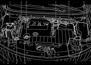
HOOD
LIFT GATE
1. Pull
the hood lock release handle *1
thelocated below the instrument panel; hood will then spring up slightly.
2. Pull the lever *2 up at the front of the hood
with your fingertips and raise the hood.
3. When closing the hood, slowly close the locks into
hood down and make sure it place.
SPA2437
WARNING
. Make sure the hood is completely closed and latched before driving. Failure to do so could cause the hood to fly open and result in an accident.
If you see steam or smoke coming from the engine compartment, to avoid injury do not open the hood.
WARNING
. Always be sure the lift gate has been closed securely to prevent it from opening while driving.
. Do not drive with the lift gate open. This could allow dangerous exhaust gases to be drawn into the vehicle. See “EXHAUST GAS (carbon mon- oxide)” in the “5. Starting and driv- ing” section of this manual.
. Do not leave children unattended inside the vehicle. They could un- knowingly activate switches or con- trols. Unattended children could become involved in serious acci- dents.
. Always be sure that hands and feet are clear of the door frame to avoid injury while closing the lift gate.
Pre-driving checks and adjustments 3-19
Model "Z51-D" EDITED: 2010/ 7/ 23
.
inserting the mechanical key into the driver’s door key cylinder and turning it to the rear of the vehicle twice.
To close the lift gate, pull down until it securely locks.
OPERATING POWER LIFT GATE (if so equipped) To operate the power lift gate, the selector lever must be in the P (Park) position.
The power lift gate will not operate if the battery voltage is low.
SPA2438
OPERATING MANUAL LIFT GATE To open the lift gate, unlock it and push the opener switch *A . Pull up the lift gate to open. The lift gate can be unlocked by:
pushing the unlock button Intelligent Key twice.
on the
pushing the lift gate request switch (if so equipped).
pushing the door handle request switch twice (if so equipped).
pushing the power door lock switch to the unlock position.
3-20 Pre-driving checks and adjustments
Black plate (154,1)
SPA2461
Power lift gate main switch The power lift gate operation can be turned on or off by the power lift gate main switch on the instrument panel.
When the power lift gate main switch is pushed to the “OFF” position, the power operation is not available by the power lift gate switch on the lift gate and lift gate opener switch.
Model "Z51-D" EDITED: 2010/ 7/ 23
Black plate (155,1)
Power open When the lift gate is fully closed, the lift gate will fully open automatically by:
pushing the power lift gate switch *A on the instrument panel pushing the lift gate opener switch *B pushing the power lift gate button *C on the Intelligent Key for more than 1 second
SPA2439
SPA2463
The hazard flashes 4 times and the outside chime sounds when the lift gate starts opening.
NOTE: The lift gate can be opened by the power lift gate switch *A or the lift gate button *C even if the lift gate is locked. The lift gate will individually unlock and open. Once the lift gate is closed, its lock will align to the vehicle’s lock or unlock status.
SPA2462
SPA2440
Power close When the lift gate is fully opened, the lift gate will fully close automatically by:
pushing the power lift gate switch *A on the instrument panel pushing the power lift gate switch *D on the lower part of the lift gate pushing the lift gate release button *C on Pre-driving checks and adjustments 3-21
Model "Z51-D" EDITED: 2010/ 7/ 23
Black plate (156,1)
the Intelligent Key for more than 1 second
The hazard flashes 4 times and the outside chime sounds when the lift gate starts closing.
motion will stop and the drive motor will disengage. The lift gate will enter the manual mode.
pushed during power open or close, the power operation will be canceled and the lift gate can be operated manually.
Reverse function The power lift gate will reverse immediately if one of the following actions is performed during power open or power close.
pushing the power lift gate switch *A on the instrument panel pushing the lift gate switch *D on the lower part of the lift gate
pushing the lift gate button the Intelligent Key.
*C on
The outside chime sounds when the lift gate starts to reverse.
*C on the The power lift gate button Intelligent Key cannot be operated when the ignition switch is in the ON position.
Auto reverse function The auto-reverse function enables the lift gate to automatically reverse when something is caught in the lift gate as it is opening or closing. When the control unit detects an obstacle, the lift gate will reverse and return to the full open or full close position.
If a second obstacle is detected, the lift gate
3-22 Pre-driving checks and adjustments
A pinch sensor is mounted on each side of the lift gate. If an obstacle is detected by the pinch sensor during power close, the lift gate will reverse and return to the full open position immediately.
NOTE: If the pinch sensor is damaged or removed, the power close function will not operate.
WARNING
There is a small distance immediately before the closed position that cannot be detected. Make sure that all passen- gers keep their hands, etc., clear from the lift gate opening before closing the lift gate.
Manual mode If power operation is not available, the lift gate can be operated manually. Power operation may not be available if multiple obstacles have been detected in a single power cycle or if the battery voltage is low. When the power lift gate main switch is in the OFF position, the lift gate can be opened manually by pushing the lift gate opener switch. If the power lift gate opener switch is
Model "Z51-D" EDITED: 2010/ 7/ 23
CAUTION
If the power lift gate does not stay open or if the lift gate unexpectedly closes at any time, do not operate the lift gate. There may be a pres- sure loss in one or both of the lift gate gas stays. Have the lift gate inspected by a NISSAN dealer.
. Do not activate the power lift gate if one or both of the lift gate gas stays are removed. Damage to the lift gate or power lift gate mechanisms may occur.
AUTO CLOSURE If the lift gate is pulled down to a partly open position, the lift gate will pull itself to the closed position.
Do not apply excessive force when the auto closure is operating. Excessive force applied may cause the mechanism to malfunction.
CAUTION
The lift gate will automatically close from a partly open position. To avoid
SPA2464
Safe Mode If the gas stays of the lift gate *1
lose pressure, the power lift gate safe mode is activated. When the safe mode is activated, the lift gate intermittently closes. Then the lift gate will be pulled to the closed and latched position by a motor.The power lift gate cannot be opened using the switches at any time in the safe mode.
Do not operate the lift gate again until checked by a NISSAN dealer.
it is
Black plate (157,1)
pinching, keep hands and fingers away from lift gate opening.
. Do not let children operate the lift
gate.
Pre-driving checks and adjustments 3-23
Model "Z51-D" EDITED: 2010/ 7/ 23
FUEL-FILLER DOOR
SPA1915
SPA2441
OPENING FUEL-FILLER DOOR To open the fuel-filler door, push the opener switch located below the instrument panel. To lock, close the fuel-filler door securely.
LIFT GATE RELEASE If discharged battery, follow these steps.
the lift gate cannot be opened due to a
1. Remove the cover inside of the lift gate with
a suitable tool.
2. Move the lever toward the direction *A as
illustrated to open the lift gate.
Have the vehicle checked by a NISSAN dealer.
3-24 Pre-driving checks and adjustments
Black plate (158,1)
FUEL-FILLER CAP
WARNING
. Gasoline is extremely flammable and highly explosive under certain conditions. You could be burned or seriously injured if it is misused or mishandled. Always stop engine and do not smoke or allow open flames or sparks near the vehicle when refueling.
. Do not attempt to top off the fuel tank after the fuel pump nozzle shuts off automatically. Continued refueling may cause fuel overflow, resulting in fuel spray and possibly a fire.
. Use only an original equipment type fuel-filler cap as a replacement. It has a built-in safety valve needed for proper operation of the fuel system and emission control sys- tem. An incorrect cap can result in a serious malfunction and possible injury. It could also cause the mal- function indicator light to come on.
. Never pour fuel
into the throttle body to attempt to start your vehi-
Model "Z51-D" EDITED: 2010/ 7/ 23
light (MIL) to illuminate. If the light illuminates because the fuel- filler cap is loose or missing, tighten or install the cap and continue to drive the vehicle. The light should turn off after a few driving trips. If the light does not turn off after a few driving trips, have the vehicle inspected by a NISSAN deal- er.
For additional information, see “Malfunction Indicator Light (MIL)” in the “2. Instruments and controls” section.
The LOOSE FUEL CAP warning will appear if the fuel-filler cap is not properly tightened. Failure to tight- en the fuel-filler cap properly after the LOOSE FUEL CAP warning ap- pears may cause the Malfunc- tion Indicator Light to illuminate.
(MIL)
cle.
. Do not fill a portable fuel container in the vehicle or trailer. Static elec- tricity can cause an explosion of flammable liquid, vapor or gas in any vehicle or trailer. To reduce the risk of serious injury or death when filling portable fuel containers:
— Always place the container on
the ground when filling.
— Do not use electronic devices
when filling.
— Keep the pump nozzle in contact with the container while you are filling it.
— Use only approved portable fuel containers for flammable liquid.
CAUTION
If fuel is spilled on the vehicle body, flush it away with water to avoid paint damage.
Insert the cap straight into the fuel- filler tube, then tighten until the fuel-filler cap clicks. Failure to tight- en the fuel-filler cap properly may cause the malfunction indicator
Black plate (159,1)
SPA2442
To remove the fuel-filler cap:
1. Turn the fuel-filler cap counterclockwise to
remove.
2. Put the fuel-filler cap on the cap holder *A
while refueling.
To install the fuel-filler cap:
1.
Insert the fuel-filler cap straight into the fuel- filler tube.
2. Turn the fuel-filler cap clockwise until a
single click is heard.
Pre-driving checks and adjustments 3-25
Model "Z51-D" EDITED: 2010/ 7/ 23
TILT/TELESCOPIC STEERING
WARNING
. Do not adjust the steering wheel while driving. You could lose control of your vehicle and cause an acci- dent.
. Do not adjust the steering wheel any closer to you than is necessary for proper steering operation and comfort. The driver’s air bag inflates with great force. If you are unrest- rained, leaning forward, sitting side- ways or out of position in any way, you are at greater risk of injury or death in a crash. You may also receive serious or fatal injuries from the air bag if you are up against it when it inflates. Always sit back against the seatback and as far away as practical from the steering wheel. Always use the seat belts.
SPA2833
LOOSE FUEL CAP warning The LOOSE FUEL CAP warning appears on the dot matrix liquid crystal display when the fuel- tightened correctly after the filler cap is not vehicle has been refueled. To turn off the warning, perform the following steps:
1. Remove and install the fuel-filler cap as soon as possible. (See “FUEL-FILLER CAP” ear- lier in this section.)
2. Tighten the fuel-filler cap until it clicks. 3. Push the reset switch *A on the right side of the combination meter for about 1 second to turn off the LOOSE FUEL CAP warning after tightening the fuel cap.
3-26 Pre-driving checks and adjustments
Black plate (160,1)
SPA2443
MANUAL OPERATION Tilt or telescopic operation Pull the lock lever *1
steering wheel desired position.forward or
down and adjust the rearward to the
Push the lock lever up securely to lock the steering wheel in place. Pull the lock lever *2
wheel up or down to the desired position.and adjust the steering
Release the lock lever to lock the steering wheel in place.
Model "Z51-D" EDITED: 2010/ 7/ 23
Black plate (161,1)
SUN VISORS
POSITIONER” later in this section.
SPA2444A
ELECTRIC OPERATION Tilt or telescopic operation Move the lever to adjust the steering wheel up or down, rearward to the desired position.
forward or
Entry/Exit function operation (if so equipped):
The automatic drive positioner system will make the steering wheel move up automatically when the driver’s door is opened with the ignition switch in the LOCK position. This lets the driver get into and out of the seat more easily.
For more information, see “AUTOMATIC DRIVE
Pre-driving checks and adjustments 3-27
SIC3451
Model "Z51-D" EDITED: 2010/ 7/ 23
Black plate (162,1)
MIRRORS
CAUTION
. Do not store the main sun visor before storing the extension sun visor.
. Do not pull the extension sun visor
forcedly downward.
1. To block out glare from the front, swing
down the main sun visor *1 .
2. To block glare from the side, remove the main sun visor from the center mount and swing it to the side *2 .
3. Draw out the extension sun visor *3
from the main sun visor to block from further glare.
3-28 Pre-driving checks and adjustments
SPA2447
SPA2143
INSIDE MIRROR Adjust the height and the angle of the inside mirror to the desired position.
Manual anti-glare type The night position *1 will reduce glare from the headlights of vehicles behind you at night. Use the day position *2 when driving in daylight hours.
WARNING
Use the night position only when ne- cessary, because it reduces rear view clarity.
Model "Z51-D" EDITED: 2010/ 7/ 23
Automatic anti-glare type The inside mirror it automatically changes reflection according to the intensity of the headlights of the following vehicle.
is designed so that
The anti-glare system will be automatically turned on when the ignition switch is pushed to the ON position.
When the anti-glare system is turned on, the indicator light *A will illuminate and excessive glare from the headlights of the vehicle behind you will be reduced.
switch *B to make the Type A: Push the inside rearview mirror operate normally and the switch indicator light will turn off. Push the again to turn the system on. Type B: Push the “*” switch *C to make the inside rearview mirror operate normally. The indicator light will turn off. Push the “I” switch *D to turn the system on. Do not allow any object to cover the sensors *E or apply glass cleaner on them. Doing so will reduce the sensitivity of the sensor, resulting in improper opera- tion.
For the compass (if so equipped) operation, see “COMPASS” in the “2. Instruments and con- trols” section.
Type A
SPA2422A
Type B
SPA2450
Black plate (163,1)
For the HomeLink® Universal Transceiver opera- tion, see “HomeLink® UNIVERSAL TRANSCEI- VER” in the “2. Instruments and controls” section.
Pre-driving checks and adjustments 3-29
Model "Z51-D" EDITED: 2010/ 7/ 23
The outside mirror will operate only when the ignition switch is in the ACC or ON position.
Turn the switch right or left to select the right or left side mirror *1 , then adjust using the control switch *2 . Defrosting outside mirrors (if so equipped) The outside mirrors will be heated when the rear window defroster switch is operated.
SPA2319
OUTSIDE MIRRORS
WARNING
Objects viewed in the outside mirror on the passenger side are closer than they appear. Be careful when moving to the right. Using only this mirror could cause an accident. Use the inside mirror or glance over your shoulder to properly judge distances to other objects.
Adjusting outside mirrors The outside mirror control switch is located on the armrest.
3-30 Pre-driving checks and adjustments
Black plate (164,1)
SPA1829
Foldable outside mirrors Fold the outside mirror by pushing it toward the rear of the vehicle.
Model "Z51-D" EDITED: 2010/ 7/ 23
AUTOMATIC DRIVE POSITIONER (if so equipped)
The automatic drive positioner system has two features: . Entry/exit function . Memory storage
ENTRY/EXIT FUNCTION This system is designed so that the driver’s seat and steering column will automatically move when the selector is in the P (Park) position. This allows the driver to get into and out of the driver’s seat more easily.
lever
The driver’s seat will slide backward and the steering wheel will move up when the driver’s door is opened with the ignition switch in the LOCK position and the Intelligent Key not inserted in the Intelligent Key port.
The driver’s seat and steering wheel will return to the previous positions when the ignition switch is pushed to the ACC position.
The driver’s seat will not return to the previous positions if the seat or steering adjusting switch is operated when the seat is at the exit position.
Cancel or activate entry/exit function The selector lever must be in the P (Park) position with the ignition switch in the OFF position.
The entry/exit
function can be activated or
Black plate (165,1)
canceled by pressing and holding the SET switch for more than 10 seconds.
The indicator lights on the memory switches (1
and 2) will blink once when the function is canceled, and the indicator lights will blink twice when the function is activated. Note that the indicator lights may illuminate after 5 seconds while holding the SET switch. This indicates readiness for linking the Intelligent Key to a stored memory position. Keep the SET switch pressed for more than 10 seconds to turn on or off the entry/exit function.The entry/exit function can also be activated or canceled if the “Lift Steering Wheel on Exit” key or “Slide Driver Seat Back on Exit” key is turned to ON or OFF in the “Comfort & Conv.” settings. (See “VEHICLE INFORMATION AND SET- TINGS” in the “4. Center display, heater, air conditioner, audio, phone and voice recognition systems” section.)
the entry/exit
Initialize entry/exit function If the battery cable is disconnected, or if the fuse opens, function will not work though this function was set on before. In such a case, after connecting the battery or replacing with a new fuse, open and close the driver’s door more than two times after the ignition switch is placed in the LOCK position from the ON position. The entry/exit function will be activated.
Pre-driving checks and adjustments 3-31
Model "Z51-D" EDITED: 2010/ 7/ 23
SIC2064
VANITY MIRROR To use the front vanity mirror, pull down the sun visor and pull up the cover.
“TILT/TELESCOPIC STEERING” earlier in this section and “OUTSIDE MIRRORS” earlier in this section.
4. Push the SET switch and, within 5 seconds,
push the memory switch (1 or 2).
The indicator light for the pushed memory switch will stay on for approximately 5
seconds after pushing the switch.If memory is stored in the same memory switch, the previous memory will be deleted.
Linking Intelligent Key to a stored mem- ory position The Intelligent Key can be linked to a stored memory position with the following procedure.
1. Follow one of the steps for storing a memory
position.
. While the indicator light
for the memory switch being set is illuminated for 5 sec- onds, push the button on the Intelligent Key.
. Push the ignition switch to the OFF position, and then push the SET switch. Push the button while pushing the memory button while the indicator light stays on for approximately 5 seconds.
If the indicator light blinks, the Intelligent Key is linked to that memory setting.
SPA2445
MEMORY STORAGE Two positions for the driver’s seat, steering column and outside mirrors can be stored in the automatic drive positioner memory. Follow these procedures to use the memory system.
1. Move the selector
lever
to the P (Park)
position.
2. Push the ignition switch to the ON position.
3. Adjust the driver’s seat, steering column and outside mirrors to the desired positions by manually operating each adjusting switch. For additional information, see “SEATS” in the “1. Safety — Seats, seat belts and supplemental restraint system” section and
3-32 Pre-driving checks and adjustments
Black plate (166,1)
Push the ignition switch to the OFF position, and button on the Intelligent Key. then push the The driver’s seat, steering wheel and outside mirrors will move to the memorized position.
Confirming memory storage . Push the ignition switch to the ON position the main and push the SET switch. memory has not been stored, the indicator light will come on for approximately 0.5
second. When the memory has stored in position, the indicator light will stay on for approximately 5 seconds.If
If the battery cable is disconnected, or if the fuse opens, the memory will be canceled. In this case, reset the desired position using the previous procedure.
If optional keys are added to your vehicle, the memory storage procedure to switch 1
or 2 and linking Intelligent Key procedure to a stored memory position should be per- formed again for each Intelligent Key. For additional Intelligent Key information, see “KEYS” earlier in this section.Selecting the memorized position 1. Move the selector
lever
to the P (Park)
position.
2. Use one of the following methods to move the driver’s seat, the outside mirrors and the steering wheel.
Model "Z51-D" EDITED: 2010/ 7/ 23
. When the engine is started while moving the
automatic drive positioner.
. When the selector lever is moved from the P (Park) position to any other position. (How- ever, it will not be canceled while the seat and steering column are returning to the previous positions (entry/exit function).)
. When the driver’s door remains open for more than 45 seconds and the ignition switch is not in the ON position.
. Push the ignition switch to the ON position and push the memory switch (1 or 2).
. Within 45 seconds of opening the driver’s door, push the memory switch (1 or 2).
The driver’s seat, steering column and outside mirrors will move to the memorized position with the indicator light flashing, and then the light will stay on for approximately 5
seconds.SYSTEM OPERATION The automatic drive positioner system will not work or will stop operating under the following conditions: . When the vehicle speed is above 4 MPH (7
km/h) (entry/exit function).
. When the vehicle is driven (memory sto-
rage).
. When the adjusting switch for the driver’s seat and steering column is turned on while the automatic drive positioner is operating. . When the seat, steering column and outside mirrors have already been moved to the memorized position.
. When no position is stored in the memory
switch.
Black plate (167,1)
Pre-driving checks and adjustments 3-33
Model "Z51-D" EDITED: 2010/ 7/ 23
Black plate (13,1)
4 Center display, heater, air conditioner, audio, phone and voice recognition systems
Safety note . . . . . . . . . . . . . . . . . . . . . . . . . . . . . . . . . . . . . . . . . . . . . . . . . . . . . . . 4-2
Center multi-function control panel (models with color display screen) . . . . . . . . . . . . . . . . . . . . . . . . . 4-2
How to use multi-function controller . . . . . . . . . . . . . . . . . . . 4-4
How to use touch screen (models with navigation system) . . . . . . . . . . . . . . . . . . . . . . . . 4-4
Menu options (models with navigation system) . . . . . . 4-6
How to select menus on the screen . . . . . . . . . . . . . . . . . . . 4-7
Vehicle information and settings (if so equipped) . . . . . . . 4-7
How to use STATUS button. . . . . . . . . . . . . . . . . . . . . . . . . . . . . . 4-7
How to use brightness control and display ON/ OFF button. . . . . . . . . . . . . . . . . . . . . . . . . . . . . . . . . . . . . . . . . . . . . . . . . . . 4-7
How to use INFO button. . . . . . . . . . . . . . . . . . . . . . . . . . . . . . . . . . 4-7
How to use SETTING button . . . . . . . . . . . . . . . . . . . . . . . . . . 4-12
RearView monitor (if so equipped) . . . . . . . . . . . . . . . . . . . . . . . 4-21
How to read the displayed lines. . . . . . . . . . . . . . . . . . . . . . . 4-22
How to park with predicted course lines. . . . . . . . . . . . 4-22
Difference between predicted and actual distances . . . . . . . . . . . . . . . . . . . . . . . . . . . . . . . . . . . . . . . . . . . . . . . . . . . 4-24
How to adjust the screen . . . . . . . . . . . . . . . . . . . . . . . . . . . . . . . 4-26
Operating tips . . . . . . . . . . . . . . . . . . . . . . . . . . . . . . . . . . . . . . . . . . . . . 4-26
Ventilators . . . . . . . . . . . . . . . . . . . . . . . . . . . . . . . . . . . . . . . . . . . . . . . . . . . . . . 4-27
Heater and air conditioner . . . . . . . . . . . . . . . . . . . . . . . . . . . . . . . . . . 4-28
Automatic operation. . . . . . . . . . . . . . . . . . . . . . . . . . . . . . . . . . . . . . 4-30
Manual operation . . . . . . . . . . . . . . . . . . . . . . . . . . . . . . . . . . . . . . . . . 4-31
To turn the system ON/OFF . . . . . . . . . . . . . . . . . . . . . . . . . . . 4-32
Operating tips . . . . . . . . . . . . . . . . . . . . . . . . . . . . . . . . . . . . . . . . . . . . . 4-32In-cabin microfilter. . . . . . . . . . . . . . . . . . . . . . . . . . . . . . . . . . . . . . . . 4-32
Servicing air conditioner . . . . . . . . . . . . . . . . . . . . . . . . . . . . . . . . 4-32
Audio system . . . . . . . . . . . . . . . . . . . . . . . . . . . . . . . . . . . . . . . . . . . . . . . . . . 4-33
Audio operation precautions . . . . . . . . . . . . . . . . . . . . . . . . . . . 4-33
FM-AM radio with Compact Disc (CD) changer . . . . . . . . . . . . . . . . . . . . . . . . . . . . . . . . . . . . . . . . . . . . . . . . . . . . . 4-46
FM-AM-SAT radio with Compact Disc (CD) player . . . . . . . . . . . . . . . . . . . . . . . . . . . . . . . . . . . . . . . . . . . . . . . . . . . . . . . . 4-51
DVD (Digital Versatile Disc) player operation (models with navigation system) . . . . . . . . . . . . . . . . . . . . . . 4-55
USB memory operation (if so equipped) . . . . . . . . . . . . 4-58
Bluetooth® streaming audio (models with navigation system) . . . . . . . . . . . . . . . . . . . . . . 4-62
iPod® player operation (if so equipped). . . . . . . . . . . . . . 4-67
Music Box® (if so equipped) . . . . . . . . . . . . . . . . . . . . . . . . . . . 4-69
Auxiliary input jacks (if so equipped) . . . . . . . . . . . . . . . . . 4-77
CD/DVD/USB memory care and cleaning . . . . . . . . . . 4-78
Steering-wheel-mounted controls for audio . . . . . . . . 4-79
Antenna . . . . . . . . . . . . . . . . . . . . . . . . . . . . . . . . . . . . . . . . . . . . . . . . . . . . . 4-81
Car phone or CB radio. . . . . . . . . . . . . . . . . . . . . . . . . . . . . . . . . . . . . . 4-82
Bluetooth® Hands-Free Phone System (models with navigation system) . . . . . . . . . . . . . . . . . . . . . . . . . . 4-82
Regulatory information . . . . . . . . . . . . . . . . . . . . . . . . . . . . . . . . . . . 4-83
Voice commands. . . . . . . . . . . . . . . . . . . . . . . . . . . . . . . . . . . . . . . . . . 4-84
Control buttons . . . . . . . . . . . . . . . . . . . . . . . . . . . . . . . . . . . . . . . . . . . 4-84
Connecting procedure. . . . . . . . . . . . . . . . . . . . . . . . . . . . . . . . . . . 4-85
Phone selection . . . . . . . . . . . . . . . . . . . . . . . . . . . . . . . . . . . . . . . . . . . 4-85Model "Z51-D" EDITED: 2010/ 7/ 23
Black plate (14,1)
Vehicle phonebook . . . . . . . . . . . . . . . . . . . . . . . . . . . . . . . . . . . . . . . 4-85
Making a call. . . . . . . . . . . . . . . . . . . . . . . . . . . . . . . . . . . . . . . . . . . . . . . 4-88
Receiving a call . . . . . . . . . . . . . . . . . . . . . . . . . . . . . . . . . . . . . . . . . . . 4-89
During a call . . . . . . . . . . . . . . . . . . . . . . . . . . . . . . . . . . . . . . . . . . . . . . . 4-90
Phone setting. . . . . . . . . . . . . . . . . . . . . . . . . . . . . . . . . . . . . . . . . . . . . . 4-90
Troubleshooting guide . . . . . . . . . . . . . . . . . . . . . . . . . . . . . . . . . . . 4-92Bluetooth® Hands-Free Phone System (models without navigation system) (if so equipped) . . . . . . . . . . . . 4-93
Regulatory information . . . . . . . . . . . . . . . . . . . . . . . . . . . . . . . . . . . 4-94
Control buttons . . . . . . . . . . . . . . . . . . . . . . . . . . . . . . . . . . . . . . . . . . . 4-94
Voice Recognition System. . . . . . . . . . . . . . . . . . . . . . . . . . . . . . 4-94
Pairing procedure. . . . . . . . . . . . . . . . . . . . . . . . . . . . . . . . . . . . . . . . . 4-99
Phonebook registration . . . . . . . . . . . . . . . . . . . . . . . . . . . . . . . . 4-100Making a call. . . . . . . . . . . . . . . . . . . . . . . . . . . . . . . . . . . . . . . . . . . . . 4-100