- Download PDF Manual
-
2. Check whether the vehicle is fitted with
normal tires or run-flat tires. Run-flat tires, refer to page 190, are la‐ beled with a circular symbol containing the letters RSC marked on the tire's sidewall.
104
Online Edition for Part no. 01 40 2 964 625 - X/15
WARNING A damaged regular tire with low or miss‐
ing tire inflation pressure impacts handling, such as steering and braking response. Run-flat tires can maintain limited stability. There is risk of an accident. Do not continue driving if the vehicle is not equipped with run-flat tires. Ob‐ serve the hints on run-flat tires and continued driving with these tires.◀ A low tire inflation pressure might turn on DSC Dynamic Stability Control. Actions in the event of a flat tire Normal tires 1.
Identify the damaged tire. Do this by checking the air pressure in all four tires. The tire pressure gauge of the Mobility Sys‐ tem, refer to page 190, can be used for this purpose. If the tire inflation pressure in all four tires is correct, the Tire Pressure Monitor may not have been initialized. In this case, initialize the system. If identification of flat tire damage is not possible, please contact a dealer’s service center or another qualified service center or repair shop.
2. Fix the flat tire using the Mobility System,
refer to page 190.
Use of tire sealant, e.g., the Mobility System, may damage the TPM wheel electronics. In this case, have the electronics checked at the next opportunity and have them replaced if needed. Run-flat tires Maximum speed You may continue driving with a damaged tire at speeds up to 50 mph/80 km/h.
Safety
CONTROLS
Continued driving with a flat tire If continuing to drive with a damaged tire: 1. Avoid sudden braking and steering maneu‐
vers.
2. Do not exceed a speed of 50 mph/80 km/h. 3. Check the air pressure in all four tires at the
next opportunity. If the tire inflation pressure in all four tires is shown to be correct, it is possible that the Tire Pressure Monitor did not perform a re‐ set. Then perform the reset.
Possible driving distance with complete loss of tire inflation pressure: The possible driving distance after a loss of tire inflation pressure depends on cargo load, driv‐ ing style and road conditions. A vehicle with an average load has a possible driving range of approx. 50 miles/80 km. A vehicle with a damaged tire reacts differently, e.g., it has reduced lane stability during brak‐ ing, a longer braking distance and different self-steering properties. Adjust your driving style accordingly. Avoid abrupt steering ma‐ neuvers or driving over obstacles, e.g., curbs, potholes, etc. Because the possible driving distance depends on how the vehicle is used during the trip, the actual distance may be shorter or longer de‐ pending on the driving speed, road conditions, external temperature, cargo load, etc.
WARNING Your vehicle handles differently when a run-flat tire is damaged and has low or missing tire inflation pressure, for example, your lane stability is reduced when braking, braking dis‐ tances are longer and the self-steering proper‐ ties will change. There is risk of an accident. Drive moderately and do not exceed a speed of 50 mph/80 km/h.◀
Online Edition for Part no. 01 40 2 964 625 - X/15
105
CONTROLS
Safety
Final tire failure Vibrations or loud noises while driving can indi‐ cate the final failure of a tire. Reduce speed and stop; otherwise, pieces of the tire could come loose and cause an acci‐ dent. Do not continue driving. Contact a dealer’s service center or another qualified service cen‐ ter or repair shop. Required inflation pressure check message A Check Control message is displayed in the fol‐ lowing situations ▷ The system has detected a wheel change,
but no reset was done.
▷ Inflation was not carried out according to
specifications.
▷ The tire inflation pressure has fallen below
the level of the last confirmation.
In this case: ▷ Check the tire pressure and correct as
needed.
▷ Carry out a reset of the system after a tire
change.
System limits The system does not function properly if a reset has not been carried out, e.g., a flat tire is re‐ ported though tire inflation pressures are cor‐ rect. The tire inflation pressure depends on the tire's temperature. Driving or exposure to the sun will increase the tire's temperature, thus in‐ creasing the tire inflation pressure. The tire in‐ flation pressure is reduced when the tire tem‐ perature falls again. These circumstances may cause a warning when temperatures fall very sharply. The system cannot indicate sudden serious tire damage caused by external circumstances.
Malfunction
The yellow warning lamp flashes and then lights up continuously. A Check Control message is displayed. No flat tire or loss of tire pressure can be detected. Examples and recommendations in the follow‐ ing situations: ▷ A wheel without TPM electronics, for exam‐ ple an emergency wheel, is mounted: Have it checked by a dealer’s service center or another qualified service center or repair shop as needed.
▷ Malfunction: Have system checked by a
dealer’s service center or another qualified service center or repair shop.
▷ TPM was unable to complete the reset. Re‐
set the system again.
▷ Interference through systems or devices
with the same radio frequency: After leav‐ ing the area of the interference, the system automatically becomes active again.
Declaration according to NHTSA/FMVSS 138 Tire Pressure Monitoring System Each tire, including the spare (if provided) should be checked monthly when cold and in‐ flated to the inflation pressure recommended by the vehicle manufacturer on the vehicle placard or tire inflation pressure label. (If your vehicle has tires of a different size than the size indicated on the vehicle placard or tire inflation pressure label, you should determine the proper tire inflation pressure for those tires.) As an added safety feature, your vehicle has been equipped with a tire pressure monitoring sys‐ tem (TPMS) that illuminates a low tire pressure telltale when one or more of your tires is signifi‐ cantly under-inflated. Accordingly, when the low tire pressure telltale illuminates, you should stop and check your tires as soon as possible, and inflate them to the proper pressure. Driving on a significantly under-inflated tire causes the tire to overheat and can lead to tire failure. Un‐ der-inflation also reduces fuel efficiency and
106
Online Edition for Part no. 01 40 2 964 625 - X/15
tire tread life, and may affect the vehicle's han‐ dling and stopping ability. Please note that the TPMS is not a substitute for proper tire mainte‐ nance, and it is the driver's responsibility to maintain correct tire pressure, even if under-in‐ flation has not reached the level to trigger illu‐ mination of the TPMS low tire pressure telltale. Your vehicle has also been equipped with a TPMS malfunction indicator to indicate when the system is not operating properly. The TPMS malfunction indicator is combined with the low tire pressure telltale. When the system detects a malfunction, the telltale will flash for approxi‐ mately one minute and then remain continu‐ ously illuminated. This sequence will continue upon subsequent vehicle start-ups as long as the malfunction exists. When the malfunction indicator is illuminated, the system may not be able to detect or signal low tire pressure as in‐ tended. TPMS malfunctions may occur for a va‐ riety of reasons, including the installation of re‐ placement or alternate tires or wheels on the vehicle that prevent the TPMS from functioning properly. Always check the TPMS malfunction telltale after replacing one or more tires or wheels on your vehicle to ensure that the re‐ placement or alternate tires and wheels allow the TPMS to continue to function properly.
FTM Flat Tire Monitor The concept The system does not measure the actual infla‐ tion pressure in the tires. It detects a tire inflation pressure loss by com‐ paring the rotational speeds of the individual wheels while moving. In the event of a tire inflation pressure loss, the diameter and therefore the rotational speed of the corresponding wheel changes. This will be detected and reported as a flat tire.
Safety
CONTROLS
"Flat Tire Monitor (FTM)"
Functional requirements The system must have been initialized when the tire inflation pressure was correct; other‐ wise, reliable flagging of a flat tire is not as‐ sured. Initialize the system after each correc‐ tion of the tire inflation pressure and after every tire or wheel change. Status display The current status of the Flat Tire Monitor can be displayed on the Control Display, e.g., whether or not the FTM is active. On the Control Display: "Vehicle info" 1. 2. "Vehicle status" 3. The status is displayed. Initialization When initializing the once set inflation tire pres‐ sures serve as reference values in order to de‐ tect a flat tire. Initialization is started by con‐ firming the inflation pressures. Do not initialize the system when driving with snow chains. On the Control Display: "Vehicle info" 1. 2. "Vehicle status" 3. 4. Start the engine - do not drive off. 5. Start the initialization with "Perform reset". 6. Drive away. The initialization is completed while driving, which can be interrupted at any time. The initialization automatically continues when driving resumes. Indication of a flat tire
"Perform reset"
The yellow warning lamp lights up. A Check Control message is displayed.
Online Edition for Part no. 01 40 2 964 625 - X/15
107
CONTROLS
Safety
There is a flat tire or a major loss in tire inflation pressure. 1. Reduce your speed and stop cautiously.
Avoid sudden braking and steering maneu‐ vers.
2. Check whether the vehicle is fitted with
normal tires or run-flat tires. Run-flat tires, refer to page 190, are la‐ beled with a circular symbol containing the letters RSC marked on the tire's sidewall.
WARNING A damaged regular tire with low or miss‐
ing tire inflation pressure impacts handling, such as steering and braking response. Run-flat tires can maintain limited stability. There is risk of an accident. Do not continue driving if the vehicle is not equipped with run-flat tires. Ob‐ serve the hints on run-flat tires and continued driving with these tires.◀ When a flat tire is indicated, DSC Dynamic Sta‐ bility Control is switched on if needed. System limits A natural, even tire inflation pressure loss in all four tires will not be recognized. Therefore, check the tire inflation pressure regularly. Sudden serious tire damage caused by external circumstances cannot be recognized in ad‐ vance. The system could be delayed or malfunction in the following situations: ▷ When the system has not been initialized. ▷ When driving on a snowy or slippery road
surface.
▷ Sporty driving style: spinning traction
wheels, high lateral acceleration (drifting).
▷ When driving with snow chains.
Actions in the event of a flat tire Normal tires 1.
Identify the damaged tire. Do this by checking the air pressure in all four tires. The tire pressure gauge of the Mobility Sys‐ tem, refer to page 190, can be used for this purpose. If the tire inflation pressure in all four tires is correct, the Flat Tire Monitor may not have been initialized. In this case, initialize the system. If identification of flat tire damage is not possible, please contact a dealer’s service center or another qualified service center or repair shop.
2. Fix the flat tire using the Mobility System,
refer to page 190.
Run-flat tires Maximum speed You may continue driving with a damaged tire at speeds up to 50 mph/80 km/h.
Continued driving with a flat tire If continuing to drive with a damaged tire: 1. Avoid sudden braking and steering maneu‐
vers.
2. Do not exceed a speed of 50 mph/80 km/h. 3. Check the air pressure in all four tires at the
next opportunity. If the tire inflation pressure in all four tires is correct, the Flat Tire Monitor may not have been initialized. In this case, initialize the system.
Possible driving distance with complete loss of tire inflation pressure: The possible driving distance after a loss of tire inflation pressure depends on cargo load, driv‐ ing style and road conditions.
108
Online Edition for Part no. 01 40 2 964 625 - X/15
A vehicle with an average load has a possible driving range of approx. 50 miles/80 km. A vehicle with a damaged tire reacts differently, e.g., it has reduced lane stability during brak‐ ing, a longer braking distance and different self-steering properties. Adjust your driving style accordingly. Avoid abrupt steering ma‐ neuvers or driving over obstacles, e.g., curbs, potholes, etc. Because the possible driving distance depends on how the vehicle is used during the trip, the actual distance may be shorter or longer de‐ pending on the driving speed, road conditions, external temperature, cargo load, etc.
WARNING Your vehicle handles differently when a run-flat tire is damaged and has low or missing tire inflation pressure, for example, your lane stability is reduced when braking, braking dis‐ tances are longer and the self-steering proper‐ ties will change. There is risk of an accident. Drive moderately and do not exceed a speed of 50 mph/80 km/h.◀
Final tire failure Vibrations or loud noises while driving can indi‐ cate the final failure of a tire. Reduce speed and stop; otherwise, pieces of the tire could come loose and cause an acci‐ dent. Do not continue driving. Contact a dealer’s service center or another qualified service cen‐ ter or repair shop.
Intelligent Safety The concept Intelligent Safety enables central operation of the driver assistance system. The intelligent safety systems can hel prevent an imminent collision.
Safety
CONTROLS
▷ Front-end collision warning with City Brak‐
ing function, refer to page 110.
▷ Person warning with City light braking func‐
tion, refer to page 113.
Information WARNING Indicators and warnings do not relieve
from the personal responsibility. Due to system limits, warnings or reactions of the system may not be output or they may be output too late or incorrectly. There is risk of an accident. Adjust the driving style to the traffic conditions. Watch traffic closely and actively interfere in the re‐ spective situations.◀
WARNING Due to system limits, individual functions
can malfunction during tow-starting/towing with the Intelligent Safety systems activated, for example approach control warning with light braking function. There is risk of an acci‐ dent. Switch all Intelligent Safety systems off prior to tow-starting/towing.◀
Overview Button in the vehicle
Intelligent Safety button
Switching on/off Some Intelligent Safety systems are automati‐ cally active after every departure. Some Intelli‐
Online Edition for Part no. 01 40 2 964 625 - X/15
109
CONTROLS
Safety
gent Safety systems activate according to the last setting.
Press button briefly: ▷ The menu for the intelligent safety
system is displayed. The systems are individually switched off ac‐ cording to their respective settings. ▷ LED lights up orange or goes out respective
to their individual settings.
Adjust as needed. Individual settings are stored for the profile currently used.
Press button again: ▷ All Intelligent Safety systems are
activated.
▷ The LED lights up green.
Hold down button: ▷ All Intelligent Safety systems are
turned off. ▷ The LED goes out.
Front-end collision warning with City Brak‐ ing function The concept The system can help prevent accidents. If an accident cannot be prevented, the system will help reduce the collision speed. The system sounds a warning before an immi‐ nent collision and actuates brakes independ‐ ently if needed. The automatic braking intervention is done with limited force and duration. The system is controlled via a camera in the base of the mirror. The front-end collision warning is available even if cruise control has been deactivated.
With the vehicle approaching another vehicle intentionally, the collision warning and braking are delayed in order to avoid false system reac‐ tions. General information The system warns at two levels of an imminent danger of collision at speeds from approx. 3 mph/5 km/h. Time of warnings may vary with the current driving situation. Appropriate braking kicks in at speeds of up to 35 mph/60 km/h. Detection range
It responds to objects if they are detected by the system.
Information WARNING Indicators and warnings do not relieve
from the personal responsibility. Due to system limits, warnings or reactions of the system may not be output or they may be output too late or incorrectly. There is risk of an accident. Adjust the driving style to the traffic conditions. Watch traffic closely and actively interfere in the re‐ spective situations.◀
WARNING Due to system limits, individual functions
can malfunction during tow-starting/towing with the Intelligent Safety systems activated, for example approach control warning with light braking function. There is risk of an acci‐
110
Online Edition for Part no. 01 40 2 964 625 - X/15
dent. Switch all Intelligent Safety systems off prior to tow-starting/towing.◀
Overview Button in the vehicle
Intelligent Safety button
Camera
Safety
CONTROLS
▷ The menu for the intelligent safety system is displayed. The systems are individually switched off according to their respective settings.
▷ LED lights up orange or goes out respective
to their individual settings.
Adjust as needed. Individual settings are stored for the profile currently used.
Press button again: ▷ All Intelligent Safety systems are
activated.
▷ The LED lights up green.
Hold down button: ▷ All Intelligent Safety systems are
turned off. ▷ The LED goes out.
Setting the warning time The warning time can be set via the onboard monitor. 1. 2. "Frontal Coll. Warning" 3. Activate the desired warning time on the
"Settings"
Control Display.
The selected warning time is stored for the pro‐ file currently used. Warning with braking function Display If a collision with a recognized vehicle is immi‐ nent a warning symbol appears in the instru‐ ment cluster and in the Head-Up Display.
The camera is installed near the interior rear‐ view mirror. Keep the windshield in the area behind the in‐ terior rearview mirror clean and clear.
Switching on/off Switching on automatically The system is automatically active after every driving-off. Switching on/off manually
Press button briefly:
Online Edition for Part no. 01 40 2 964 625 - X/15
111
CONTROLS
Safety
Symbol Measure
Symbol lights up red: prewarning. Brake and increase distance. Symbol flashes red and an acoustic signal sounds: acute warning. You are requested to intervene by braking or make an evasive maneu‐ ver.
Prewarning This warning is issued, for example, when there is the impending danger of a collision or the distance to the vehicle ahead is too small. The driver must intervene actively when there is a prewarning. Acute warning with braking function Acute warning in displayed in case of the immi‐ nent danger of a collision when the vehicle ap‐ proaches another object at a high differential speed. The driver must intervene actively when there is an acute warning. If necessary, the driver is assisted by a minor automatic braking inter‐ vention in a possible risk of collision. Acute warnings can also be triggered without previous forewarning. Braking intervention The warning prompts the driver himself/herself to react. During a warning, the maximum brak‐ ing force is used. Premise for the brake booster is sufficiently quick and sufficiently hard step‐ ping on the brake pedal. The system can assist with some braking intervention if there is risk of a collision. At low speeds vehicles may thus come to a complete stop. Manual transmission: During a braking inter‐ vention up to a complete stop, the engine may be shut down. The braking intervention is executed only if DSC Dynamic Stability Control is switched on.
The braking intervention can be interrupted by stepping on the accelerator pedal or by actively moving the steering wheel. Object detection can be restricted. Limitations of the detection range and functional restric‐ tions are to be considered. System limits Information WARNING The system can react incorrectly or not at all due to the system limits. There is risk of acci‐ dents or risk of property damage. Observe the system limits and actively interfere if needed.◀
Detection range The system's detection potential is limited. Thus a system reaction might not come or might come late. E. g. the following situations may not be de‐ tected: ▷ Slow moving vehicles when you approach
them at high speed.
▷ Vehicles that suddenly swerve in front of
you, or sharply decelerating vehicles.
▷ Vehicles with an unusual rear appearance. ▷ Two-wheeled vehicles ahead of you. Functional limitations The system may not be fully functional in the following situations: ▷ In heavy fog, rain, sprayed water or snow‐
fall.
▷ In tight curves. ▷ If the field of view of the camera or the
front windshield are dirty or covered.
▷ If the driving stability control systems are
deactivated, for example DSC OFF.
▷ Up to 10 seconds after the start of the en‐
gine, via the Start/Stop button.
112
Online Edition for Part no. 01 40 2 964 625 - X/15
▷ During calibration of the camera immedi‐
ately after vehicle delivery.
▷ If there are constant blinding effects be‐
cause of oncoming light, e. g., from the sun low in the sky.
Warning sensitivity The more sensitive the warning settings are, the more warnings are displayed. However, there may also be an excess of false warnings.
Person warning with City light braking function The concept The system can help prevent accidents with pe‐ destrians. The system issues a warning in the city driving speed area if there is imminent danger of a col‐ lision with pedestrians and includes a braking function. A camera at the base of the rearview mirror controls the system. General information With sufficient brightness, the system warns about possible collision danger with pedes‐ trians starting at approx. 6 mph/10 km/h to ap‐ prox. 35 mph/60 km/h and assists with braking before a collision. Under those circumstances it reacts to people who are within the detection range of the sys‐ tem.
Safety
CONTROLS
Detection range
The detection area in front of the vehicle is div‐ ided into two areas ▷ Central area, arrow 1, directly in front of the
vehicle.
▷ Expanded area, arrow 2, to the right and
left.
A collision is imminent if pedestrians are lo‐ cated within the central area. A warning is is‐ sued about pedestrians who are located within the extended area only if they are moving in the direction of the central area.
Information WARNING Indicators and warnings do not relieve
from the personal responsibility. Due to system limits, warnings or reactions of the system may not be output or they may be output too late or incorrectly. There is risk of an accident. Adjust the driving style to the traffic conditions. Watch traffic closely and actively interfere in the re‐ spective situations.◀
WARNING Due to system limits, individual functions
can malfunction during tow-starting/towing with the Intelligent Safety systems activated, for example approach control warning with light braking function. There is risk of an acci‐ dent. Switch all Intelligent Safety systems off prior to tow-starting/towing.◀
Online Edition for Part no. 01 40 2 964 625 - X/15
113
CONTROLS
Safety
Overview Button in the vehicle
Intelligent Safety button
Camera
The camera is installed near the interior rear‐ view mirror. Keep the windshield in the area behind the in‐ terior rearview mirror clean and clear.
Switching on/off Switching on automatically The system is automatically active after every driving-off. Switching on/off manually
Press button briefly: ▷ The menu for the intelligent safety
system is displayed. The systems are individually switched off ac‐ cording to their respective settings.
▷ LED lights up orange or goes out respective
to their individual settings.
Adjust as needed. Individual settings are stored for the profile currently used.
Press button again: ▷ All Intelligent Safety systems are
activated.
▷ The LED lights up green.
Hold down button: ▷ All Intelligent Safety systems are
turned off. ▷ The LED goes out.
Warning with braking function Display If a collision with a person detected in this way is imminent, a warning symbol appears on the instrument cluster and in the Head-up Display. The red symbol is displayed and a signal sounds. Intervene immediately by braking or
make an evasive maneuver.
Braking intervention The warning prompts the driver himself/herself to react. During a warning, the maximum brak‐ ing force is used. Premise for the brake booster is sufficiently quick and sufficiently hard step‐ ping on the brake pedal. The system can assist with some braking intervention if there is risk of a collision. At low speeds vehicles may thus come to a complete stop. Manual transmission: During a braking inter‐ vention up to a complete stop, the engine may be shut down. The braking intervention is executed only if DSC Dynamic Stability Control is switched on.
114
Online Edition for Part no. 01 40 2 964 625 - X/15
The braking intervention can be interrupted by stepping on the accelerator pedal or by actively moving the steering wheel. Object detection can be restricted. Limitations of the detection range and functional restric‐ tions are to be considered. System limits Information WARNING The system can react incorrectly or not at all due to the system limits. There is risk of acci‐ dents or risk of property damage. Observe the system limits and actively interfere if needed.◀
Detection range The detection potential of the camera is lim‐ ited. Thus a warning might not be issued or be is‐ sued late. E. g. the following situations may not be de‐ tected: ▷ Partially covered pedestrians. ▷ Pedestrians that are not detected as such because of the viewing angle or contour.
▷ Pedestrians outside of the detection range. ▷ Pedestrians having a body size less than
32 inches/80 cm.
Functional limitations The system may not be fully functional or may not be available in the following situations: ▷ In heavy fog, rain, sprayed water or snow‐
fall.
▷ In tight curves. ▷ If the field of view of the camera or the
front windshield are dirty or covered.
▷ If the driving stability control systems are
deactivated, for example DSC OFF.
Safety
CONTROLS
▷ Up to 10 seconds after the start of the en‐
gine, via the Start/Stop button.
▷ During calibration of the camera immedi‐
ately after vehicle delivery.
▷ If there are constant blinding effects be‐
cause of oncoming light, e. g., from the sun low in the sky.
▷ When it is dark outside.
Brake force display The concept
▷ During normal brake application, the brake
lights light up.
▷ During heavy brake application, the flash‐
ers light up in addition.
PostCrash In the event of an accident, the system can bring the car to a halt automatically without in‐ tervention by the driver in certain situations. This can reduce the risk of a further collision and the consequences thereof. Depressing the brake pedal can cause the vehi‐ cle to brake harder. This interrupts automatic braking. Destepping on the gas pedal also in‐ terrupts automatic braking. After coming to a halt, the brake is released au‐ tomatically. Secure the vehicle against rolling.
Online Edition for Part no. 01 40 2 964 625 - X/15
115
CONTROLS
Driving stability control systems
Driving stability control systems DSC Dynamic Stability Vehicle features and op‐ Control tions This chapter describes all standard, country- The concept specific and optional features offered with the Dynamic Stability Control detect for example series. It also describes features that are not the following unstable driving conditions: necessarily available in your car, e. g., due to ▷ Fishtailing, which can lead to oversteering. the selected options or country versions. This also applies to safety-related functions and sys‐ ▷ Loss of traction of the front wheel, which tems. The respectively applicable country provi‐ sions must be observed when using the respec‐ tive features and systems.
can lead to understeering.
Anti-lock Braking System ABS ABS prevents locking of the wheels during braking. The vehicle contains its steering power even during full brake applications, thus increasing active safety. ABS is operational every time you start the en‐ gine.
Brake assistant When you apply the brakes rapidly, this system automatically produces the greatest possible braking force boost. It reduces the braking dis‐ tance to a minimum during emergency stop. This system utilizes all of the benefits provided by ABS. Do not reduce the pressure on the brake pedal for the duration of the emergency stop.
Within the physical limits, the system helps to keep the vehicle on a steady course by reduc‐ ing engine speed and by applying brakes to the individual wheels. Information The system does not relieve the driver from his responsibility to adjust his driving style accord‐ ing to the situation. Therefore, adjust the driving style according to the situation and do not reduce the additional safety margin by driving in a risky manner.
WARNING When driving with roof load, for example with roof-mounted luggage rack, driving safety may not be ensured in driving-critical situations due to the elevated center of gravity. There is risk of accidents or risk of property damage. Do not deactivate Dynamic Stability Control DSC when driving with roof load.◀
Indicator/warning lights
The indicator lamp flashes: DSC controls the drive and braking forces. The indicator lamp lights up: DSC has
failed.
116
Online Edition for Part no. 01 40 2 964 625 - X/15
Driving stability control systems
CONTROLS
Deactivating DSC: DSC OFF When DSC is deactivated, driving stability is re‐ duced during acceleration and when driving in curves. To increase vehicle stability, activate DSC again as soon as possible. Deactivating DSC
Press and hold this button but not lon‐ ger than approx. 10 seconds, until the indicator lamp for DSC OFF lights up in the in‐ strument cluster and displays DSC OFF. DSC is switched off.
Activating DSC
Press button. DSC OFF and the DSC OFF indicator
lamp go out.
Indicator/warning lights When DSC is deactivated, DSC OFF is displayed in the instrument cluster.
The indicator lamp lights up: DSC is de‐ activated.
Automatic activation When DSC is deactivated, automatic activation occurs in the following situations: ▷ The vehicle has a flat tire. ▷ When activating cruise control in TRACTION
or DSC OFF mode.
DTC Dynamic Traction Control The concept DTC is a version of the DSC where forward mo‐ mentum is optimized.
The system ensures maximum headway on special road conditions, for example unplowed snowy roads or loose road surfaces, but with somewhat limited vehicle stability. When DTC is activated, the vehicle has maxi‐ mum traction. Driving stability is limited during acceleration and when driving in curves. Therefore drive with appropriate caution. You may find it useful to briefly activate DTC under the following special circumstances: ▷ When driving in slush or on uncleared,
snow-covered roads.
▷ When freeing vehicle from deep snow or
driving off from loose grounds. ▷ When driving with snow chains. Deactivating/activating DTC Dynamic Traction Control Activating DTC
Press button. TRACTION is displayed in the instru‐ ment cluster and the indicator lamp for DSC OFF lights up.
Deactivating DTC
Press button again. TRACTION and the DSC OFF indicator
lamp go out.
Performance Control Performance Control enhances the agility of the vehicle. To increase maneuverability, with a corre‐ spondingly sporty driving style, wheels are braked individually.
Online Edition for Part no. 01 40 2 964 625 - X/15
117
CONTROLS
Driving stability control systems
Dynamic Damping Con‐ trol The concept The tuning of the suspension can be changed with the system. Programs The system offers several different programs. Select the programs via the Driving Dynamics Control, refer to page 118. MID/GREEN Balanced tuning of the shock absorbers for more comfort. SPORT Consistently sporty tuning of the shock absorb‐ ers for greater driving agility.
Driving Dynamics Con‐ trol The concept The Driving Dynamics Control helps to fine- tune the vehicle's settings and features. Choose between three different programs. Driving Dy‐ namics Control will activate the particular pro‐ gram. Operating the programs
Program MID GREEN SPORT
Driving Dynamics Control
MID For balanced tuning.
118
With each starting operation, MID is activated using the Start/Stop button. GREEN GREEN, refer to page 167, provides consistent tuning to maximize range. Activating GREEN Turn Driving Dynamics Control to the right until GREEN is displayed in the instrument cluster. Configuring GREEN Via the Driving Dynamics Control 1. Activate GREEN. 2. "Configure GREEN" 3. Configure the program. This configuration is retrieved when GREEN is activated.
"Settings"
Via onboard monitor: "Settings" 1. 2. "GREEN Mode" or 1. 2. "Driving mode" 3. "Configure GREEN" Configure the program. This configuration is retrieved when GREEN is activated. SPORT Consistently sporty tuning of the drivetrain for greater driving agility. With the appropriate equipment, the tuning of the suspension also changes and SPORT can be individually configured. The configuration is stored for the profile cur‐ rently used.
Online Edition for Part no. 01 40 2 964 625 - X/15
Driving stability control systems
CONTROLS
Display on the onboard monitor Program changes can be displayed on the on‐ board monitor. 1. 2. "Control display" 3. "Driving mode info"
"Settings"
Drive-off assistant The concept This system supports driving off on inclines. The parking brake is not required. Driving off with the drive-off assistant 1. Hold the vehicle in place with the foot
brake.
2. Release the foot brake and drive off with‐
out delay.
After the foot brake is released, the vehicle is held in place for approx. 2 seconds. For vehicles with respective equipment ver‐ sions, the possible holding duration amounts to 2 minutes.
Activating SPORT Turn Driving Dynamics Control to the left until SPORT is displayed in the instrument cluster. Configuring SPORT Depending on your vehicle's optional features, when the display is activated on the Control Display, the SPORT driving mode can be config‐ ured for individual specifications. Activating SPORT. Select "Configure SPORT". Configure the program. SPORT can also be configured before it is acti‐ vated: 1. 2. "Driving mode" 3. "Configure SPORT" This configuration is retrieved when SPORT is activated. Configuring driving program Settings can be made for the following driving programs in Driving mode: ▷ GREEN, refer to page 118. ▷ SPORT, refer to page 118. Displays Program selection
"Settings"
With Driving Dynamics Control turned on a list of programs is displayed and can be selected.
Selected program
The instrument cluster displays the selected program.
Online Edition for Part no. 01 40 2 964 625 - X/15
119
CONTROLS
Driving comfort
Driving comfort Vehicle features and op‐ tions This chapter describes all standard, country- specific and optional features offered with the series. It also describes features that are not necessarily available in your car, e. g., due to the selected options or country versions. This also applies to safety-related functions and sys‐ tems. The respectively applicable country provi‐ sions must be observed when using the respec‐ tive features and systems.
Camera-based cruise con‐ trol The concept Use this system to select a desired speed that the vehicle will maintain automatically on clear roads. To the extent possible, the system automati‐ cally adjusts the speed to a slower vehicle ahead of you. A camera on the interior rear view mirror is used to detect vehicles driving ahead. The distance that the vehicle maintains to the vehicle ahead of you can be varied. For safety reasons, it depends on the speed. To maintain a certain distance, the system au‐ tomatically decelerates, applies the brakes lightly, or accelerates again if the vehicle ahead begins moving faster. As soon as the road is clear, the vehicle acceler‐ ates to the desired speed. The speed is also maintained downhill, but may not be maintained uphill if engine power is in‐ sufficient.
General information The system is functional at speeds beginning at approx. 20 mph/30 km/h. Active cruise control is paused below approx. 20 mph/30 km/h. The system does not brake to a stop. Depending on the driving program, refer to page 118, set, the characteristics of the cruise control in particular areas can change. Information WARNING The system does not relieve from the per‐ sonal responsibility to correctly assess the traf‐ fic situation. Based on the limits of the system, it cannot independently react to all traffic situa‐ tions. There is risk of an accident. Adjust the driving style to the traffic conditions. Watch traffic closely and actively interfere in the re‐ spective situations.◀
WARNING The system does not relieve from the per‐ sonal responsibility to correctly assess visibility and traffic situation. There is risk of an accident. Adjust the driving style to the traffic conditions. Watch traffic closely and actively interfere in the respective situations.◀
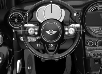
Overview Buttons on the steering wheel
Press button Function
Cruise control on/off, refer to page 121
Store/maintain speed, refer to page 122120
Online Edition for Part no. 01 40 2 964 625 - X/15
Driving comfort
CONTROLS
Press button Function
Pause cruise control, refer to page 121
Continue cruise control with the last setting, refer to page 122
Reduce distance, refer to page 122
Increase distance, refer to page 122
Increase, maintain, and store speed, refer to page 122
Reduce, maintain, and store speed, refer to page 122Buttons are arranged according to vehicle's ser‐ ies, optional features and country specifica‐ tions. Camera
The camera is installed near the interior rear‐ view mirror. Keep the windshield in the area behind the in‐ terior rearview mirror clean and clear.
Switching on/off and interrupting cruise control Switching on
Press button on the steering wheel.
Display in the instrument cluster lights up.
Display in the instrument cluster lights up. The current speed is adopted as de‐ sired speed and displayed with symbol.
Cruise control is active and maintains the set speed. DSC will be switched on if needed. Switching off
Press button on the steering wheel.
The displays go out. The stored desired speed is deleted. Interrupting
Press button on the steering wheel.
The system is automatically interrupted in the following situations: ▷ When the brakes are applied. ▷ If the clutch pedal is depressed for a few
seconds or released while a gear is not en‐ gaged.
▷ If selector lever position N is set. ▷ When DTC is activated or DSC is deacti‐
vated.
▷ When DSC is actively controlling stability. ▷ If the detection range of the camera is im‐ paired, e.g., by soiling, heavy precipitation or glare effects from the sun.
▷ If the vehicle in front decelerates below a
speed of approx. 20 mph/30 km/h.
Online Edition for Part no. 01 40 2 964 625 - X/15
121
CONTROLS
Driving comfort
Maintaining, storing, and changing the speed Information WARNING The desired speed can be incorrectly ad‐ justed or called up by mistake. There is risk of an accident. Adjust the desired speed to the traffic conditions. Watch traffic closely and ac‐ tively interfere in the respective situations.◀
WARNING Risk of accident due to too high speed
differences to other vehicles, for example in the following situations: ▷ When fast approaching a slowly moving ve‐
hicle.
▷ Suddenly swerving vehicle onto the own
lane.
▷ When fast approaching standing vehicles. There is risk of injuries or danger to life. Watch traffic closely and actively interfere in the re‐ spective situations.◀
Maintaining/storing the speed
Press button. Or: or
button in the interrupted state.
Press When the system is switched on, the current speed is maintained and stored as the desired speed.
The speed is displayed on the symbol. DSC will be switched on if needed.
Changing the speed
button: press until the desired speed
or is set. If active, the displayed speed is stored and the vehicle reaches the stored speed when the road is clear.
▷
▷
or
button: each time it is pressed to the point of resistance, the desired speed increases or decreases by approx. 1 mph/1 km/h.
or
button: each time it is pressed past the point of resistance, the desired speed increases or decreases by a maxi‐ mum of 5 mph/10 km/h. or
button: hold down to repeat the cor‐
responding action. Distance
WARNING The system does not relieve from the per‐
sonal responsibility. Due to the system limits, braking can be late. There is risk of accidents or risk of property damage. Be aware to the traffic situation at all times. Adjust the distance to the traffic and weather conditions and maintain the prescribed safety distance, possibly by brak‐ ing.◀
Reduce distance
Press button repeatedly until the de‐ sired distance is set.
The set distance is briefly displayed in the left part of the instrument cluster.
Increase distance
Press button repeatedly until the de‐ sired distance is set.
The set distance is briefly displayed in the left part of the instrument cluster.
Continue cruise control While driving
Press button with the system inter‐ rupted. Cruise control is continued with
122
Online Edition for Part no. 01 40 2 964 625 - X/15
Driving comfort
CONTROLS
the saved values. The selected distance is briefly displayed in the info display. In the following cases, the stored speed value is deleted and cannot be called up again: ▷ When the system is switched off. ▷ When the ignition is switched off. Changing between cruise control with/ without distance control
WARNING The system does not react to traffic driv‐
ing ahead of you, but instead maintains the stored speed. There is risk of accidents or risk of property damage. Adjust the desired speed to the traffic conditions and brake as needed.◀ Changing to Active Cruise Control without dis‐ tance control:
Press and hold this button, or
Press and hold this button.
The indicator lamp in the instrument cluster lights up.
To switch back to cruise control, press one of the buttons briefly. After switching, a Check Control message is dis‐ played. Displays in the instrument cluster Desired speed
In addition to the indicator lamp, the desired speed is displayed in the central information display.
▷ The indicator lights up green: the system is
active.
▷ The indicator lights up orange: the system
has been interrupted.
▷ No display: system is switched off.
If no speed is indicated, it is possible that the conditions necessary for operation are not cur‐ rently fulfilled.
Distance to vehicle ahead of you Selected distance from the vehicle driving ahead is briefly displayed in the left hand por‐ tion of the info display. Distance display
Distance 1
Distance 2
Distance 3
Distance 4
This value is set automatically after the system is switched on.Indicator/warning lights
Symbol lights up orange: A vehicle has been detected ahead of you.
Symbol flashes orange: The conditions are not adequate for the system to work.
The system was deactivated but applies the brakes until you actively resume control by pressing on the brake pedal or accelerator pedal.
Symbol flashes red and a signal sounds: You are requested to intervene by brak‐ ing or make an evasive maneuver.
The system has been interrupted or dis‐ tance control is temporarily suppressed
Online Edition for Part no. 01 40 2 964 625 - X/15
123
CONTROLS
Driving comfort
because the accelerator pedal is being pressed; a vehicle was not detected.
Detection range
Distance control is temporarily sup‐ pressed because the accelerator pedal is being pressed; a vehicle was de‐
tected.
Displays in the Head-up Display The information from Active Cruise Control can also be displayed in the Head-up Display. Adjusting the Head-up Display, refer to page 90. System limits Information WARNING The system can react incorrectly or not at all due to the system limits. There is risk of acci‐ dents or risk of property damage. Observe the system limits and actively interfere if needed.◀
Speed range The system is best used on well-constructed roads. The system is functional at speeds be‐ ginning at approx. 20 mph/30 km/h. The max. speed that can be set is 85 mph/140 km/h. Comply with the legal speed limit and safety distance in every situation when using the sys‐ tem.
The detection capacity of the system and the automatic braking capacity are limited. Two-wheeled vehicles for instance might not be detected.
WARNING The system does not relieve from the per‐ sonal responsibility to correctly assess the traf‐ fic situation. Based on the limits of the system, it cannot independently react to all traffic situa‐ tions. There is risk of an accident. Adjust the driving style to the traffic conditions. Watch traffic closely and actively interfere in the re‐ spective situations.◀
Deceleration The system also does not decelerate in the fol‐ lowing situations: ▷ In case of pedestrians, cyclists or similar
slow road users.
▷ For red traffic lights. ▷ For cross traffic. ▷ For oncoming traffic. ▷ Unlit vehicles or vehicles with nonworking
lighting at night.
124
Online Edition for Part no. 01 40 2 964 625 - X/15
Driving comfort
CONTROLS
Swerving vehicles
Cornering
A vehicle driving in front of you is not detected until it is completely within the same lane as your vehicle. If a vehicle driving ahead of you suddenly swerves into your lane, the system may not be able to automatically restore the selected dis‐ tance. This also applies to major speed differ‐ ences to vehicles driving ahead of you, for ex‐ ample, when rapidly approaching a truck. When a vehicle driving ahead of you is reliably detected, the system requests that the driver intervene by braking and carrying out evasive maneuvers, if needed.
WARNING The system does not relieve from the per‐ sonal responsibility to correctly assess the traf‐ fic situation. Based on the limits of the system, it cannot independently react to all traffic situa‐ tions. There is risk of an accident. Adjust the driving style to the traffic conditions. Watch traffic closely and actively interfere in the re‐ spective situations.◀
If the desired speed is too high for a curve, the speed is reduced slightly, although curves can‐ not be anticipated in advance. Therefore, drive into a curve at an appropriate speed. In tight curves the system offers only restricted detection where a vehicle ahead of you might be detected late or not at all.
When you approach a curve the system may briefly report vehicles in the next lane due to the bend of the curve. If the system decelerates you may compensate it by briefly accelerating. After releasing the gas pedal the system is reac‐ tivated and controls speed independently.
Weather In the event of unfavorable weather and light conditions, e. g. if there is rain, snowfall, slush, fog or glare, this may result in poorer recogni‐ tion of vehicles as well as short-term interrup‐ tions for vehicles that are already detected. Drive attentively, and react to the current traffic situation. If necessary, intervene actively, for example by braking, steering or evading.
Online Edition for Part no. 01 40 2 964 625 - X/15
125
CONTROLS
Driving comfort
Malfunction A Check Control message is displayed if the sys‐ tem fails or was automatically deactivated. The system may not be fully functional in the following situations: ▷ When an object was not correctly detected. ▷ In heavy fog, rain, sprayed water or snow‐
fall.
▷ In tight curves. ▷ If the field of view of the camera or the
front windshield are dirty or covered.
▷ When driving toward bright lights. ▷ Up to 20 seconds after the start of the en‐
gine, via the Start/Stop button.
▷ During calibration of the camera immedi‐
ately after vehicle delivery.
Cruise control The concept The system is functional at speeds beginning at approx. 20 mph/30 km/h. It maintains the speed that was set using the control elements on the steering wheel. The system brakes on downhill gradients if en‐ gine braking is insufficient. Information WARNING The system does not relieve from the per‐ sonal responsibility to correctly assess the traf‐ fic situation. Based on the limits of the system, it cannot independently react to all traffic situa‐ tions. There is risk of an accident. Adjust the driving style to the traffic conditions. Watch traffic closely and actively interfere in the re‐ spective situations.◀
WARNING The use of the system can lead to an in‐ creased risk of accidents in the following situa‐ tions: ▷ On winding roads. ▷ In heavy traffic. ▷ On slippery roads, in fog, snow or rain, or
on a loose road surface.
There is risk of accidents or risk of property damage. Only use the system if driving at con‐ stant speed is possible.◀
General information Depending on the driving program, refer to page 118, set, the characteristics of the cruise control in particular areas can change. Overview Buttons on the steering wheel
Press button Function
Cruise control on/off
Store speed
Pausing cruise control Continue cruise control with the last setting Increasing, maintaining or storing the speed Reducing, maintaining or storing the speed
Controls Switching on
Press button on the steering wheel.
126
Online Edition for Part no. 01 40 2 964 625 - X/15
Driving comfort
CONTROLS
The indicator lamp in the instrument cluster lights up.
traffic conditions. Watch traffic closely and ac‐ tively interfere in the respective situations.◀
The current speed is adopted as the de‐ sired speed and is displayed with the symbol in the instrument cluster.
Maintaining/storing the speed
Press button.
Cruise control is active and maintains the set speed. DSC will be switched on if needed. Switching off
Press button on the steering wheel.
The displays go out. The stored desired speed is deleted. Interrupting
When active, press the button on the steering wheel.
The system is automatically interrupted in the following situations: ▷ When the brakes are applied. ▷ If the clutch pedal is depressed for a few
seconds or released while a gear is not en‐ gaged.
▷ If the gear engaged is too high for the cur‐
rent speed.
▷ If selector lever position N is set. ▷ When DTC is activated or DSC is deacti‐
vated.
▷ When DSC is actively controlling stability. Maintaining, storing, and changing the speed Information
WARNING The desired speed can be incorrectly ad‐ justed or called up by mistake. There is risk of an accident. Adjust the desired speed to the
Or
or
button: press while the system is in‐
terrupted. When the system is switched on, the current speed is maintained and stored as the desired speed. This is displayed in the instrument cluster. DSC will be switched on if needed.
Changing the speed
or
button: press repeatedly until the de‐
sired speed is set. If active, the displayed speed is stored and the vehicle reaches the stored speed when the road is clear. ▷
button: each time it is pressed to the point of resistance, the desired speed increases or decreases by approx. 1 mph/1 km/h.
or
▷
▷
or
button: each time it is pressed past the point of resistance, the desired speed increases or decreases by a maxi‐ mum of 5 mph/10 km/h. The maximum speed that can be set de‐ pends on the vehicle.
or
button: pressing it to the resist‐ ance point and holding it there accelerates or decelerates the vehicle without requiring pressure on the accelerator pedal. After the button is released, the vehicle maintains its final speed. Pressing the switch beyond the resistance point causes the vehicle to accel‐ erate more rapidly.
Online Edition for Part no. 01 40 2 964 625 - X/15
127
CONTROLS
Driving comfort
The maneuvering range, depending on obsta‐ cles and environmental conditions, is approx. 6 ft/2 m. An acoustic warning is first given with the fol‐ lowing circumstances: ▷ By the front middle sensors and the two
corner sensors at approx. 24 inches/60 cm.
▷ By the rear middle sensors at approx.
5 ft/1.50 m.
▷ When a collision is imminent Information Loud noises from outside and inside the vehicle may prevent you from hearing the PDC's signal tone.
WARNING The system does not relieve from the per‐ sonal responsibility to correctly assess the traf‐ fic situation. There is risk of an accident. Adjust the driving style to the traffic conditions. Watch traffic and vehicle surroundings closely and ac‐ tively interfere in the respective situations.◀
WARNING Due to high speeds when PDC is acti‐
vated, the warning can be delayed due to phys‐ ical circumstances. There is risk of injuries or risk of property damage. Avoid approaching an object too fast. Avoid driving off fast while PDC is not yet active.◀
Overview With front PDC: button in vehicle
Continue cruise control
Press button on the steering wheel.
The stored speed is reached and maintained. Displays in the instrument cluster Indicator lamp
Depending on how the vehicle is equip‐ ped, the indicator lamp in the instru‐ ment cluster indicates whether the sys‐
tem is switched on.
Desired speed
The desired speed is displayed together with the symbol. ▷ The indicator lights up green: the
system is active.
▷ The indicator lights up orange: the system
has been interrupted.
▷ No display: system is switched off. If no speed is indicated, it is possible that the conditions necessary for operation are not cur‐ rently fulfilled.
PDC Park Distance Con‐ trol The concept PDC is a support when parking. When you slowly approach an object in the rear - or also in the front of the vehicle if the feature is avail‐ able - then the object is reported through: ▷ Signal tones. ▷ Visual display. General information Ultrasound sensors in the bumpers measure the distances from objects.
128
Online Edition for Part no. 01 40 2 964 625 - X/15
PDC Park Distance Control
Ultrasound sensors
Ultrasound sensors of the PDC, for example in the bumpers.
Functional requirements To ensure full functionality: ▷ Do not cover sensors, for example, with
stickers, bicycle racks.
▷ Keep the sensors clean and free of ice. To clean: when using high-pressure washers, do not spray the sensors for long periods and maintain a distance of at least 12 inches/30 cm. Switching on/off Switching on automatically PDC switches on automatically in the following situations: ▷ If selector lever position R is engaged when
the engine is running. The rearview camera also switches on. ▷ With front PDC: when obstacles are de‐
tected behind or in front of the vehicle by PDC and the speed is slower than approx. 2.5 mph/4 km/h.
With front PDC: You can switch off automatic activation on obstacle detection: 1. 2. "Parking" 3. Select setting.
"Settings"
Settings are stored for the profile currently used.
Driving comfort
CONTROLS
Automatic deactivation during forward travel The system switches off when a certain driving distance or speed is exceeded. Switch the system back on if needed. With front PDC: switching on/off manually
Press button.
▷ On: the LED lights up. ▷ Off: the LED goes out. The rearview camera image is displayed when the reverse gear is engaged by pressing the button. Display Signal tones When approaching an object, an intermittent sound indicates the position of the object. E. g. if an object is detected to the left rear of the ve‐ hicle, a signal tone sounds from the left rear speaker. The shorter the distance to the object, the shorter the intervals. If the distance to a detected object is less than approx. 10 inches/25 cm, a continuous tone is sounded. With front PDC: if objects are located both in front of and behind the vehicle, an alternating continuous signal is sounded. The signal tone is switched off, when selector lever position P is engaged on vehicles with Steptronic transmission. Volume The ratio of the PDC signal tone volume to the entertainment volume can be adjusted. "Radio" or 1.
"Multimedia",
"Settings"
2. "Tone"
Online Edition for Part no. 01 40 2 964 625 - X/15
129
CONTROLS
Driving comfort
3. "Volume settings" 4. "PDC" 5. To adjust: turn the Controller. 6. To store: press the Controller. Settings are stored for the profile currently used. Visual warning The approach of the vehicle to an object can be shown on the Control Display. Objects that are farther away are already displayed on the Con‐ trol Display before a signal sounds. A display appears as soon as Park Distance Control (PDC) is activated. The range of the sensors is represented in col‐ ors: red, green and yellow. When the image of the rearview camera is dis‐ played, the switch can be made to PDC:
"Rear view camera"
System limits Information WARNING The system can react incorrectly or not at all due to the system limits. There is risk of acci‐ dents or risk of property damage. Observe the system limits and actively interfere if needed.◀
Limits of ultrasonic measurement Ultrasonic measuring might not function under the following circumstances: ▷ For small children and animals. ▷ For persons with certain clothing, for exam‐
ple coats.
▷ With external interference of the ultra‐
sound, for example from passing vehicles or loud machines.
▷ When sensors are dirty, iced over, damaged
or out of position. ▷ If cargo protrudes.
▷ Under certain weather conditions such as high relative humidity, rain, snowfall, ex‐ treme heat or strong wind.
▷ With tow bars and trailer couplings of other
vehicles.
▷ With thin or wedge-shaped objects. ▷ With moving objects. ▷ With elevated, protruding objects such as
ledges or cargo.
▷ With objects with corners and sharp edges. ▷ With objects with a fine surface structure
such as fences.
▷ For objects with porous surfaces. Low objects already displayed, for example, curbs, can move into the blind area of the sen‐ sors before or after a continuous tone sounds. False warnings PDC may issue a warning under the following conditions even though there is no obstacle within the detection range: ▷ In heavy rain. ▷ When sensors are very dirty or covered with
ice.
▷ When sensors are covered in snow. ▷ On rough road surfaces. ▷ On uneven surfaces, such as speed bumps. ▷ In large buildings with right angles and
smooth walls, for example, in underground garages.
▷ In automatic car washes. ▷ Through heavy pollution. ▷ Due to other ultrasound sources, for exam‐
ple, sweeping machines, high pressure steam cleaners or neon lights. The malfunction is signaled by a continuous tone alternating between the front and rear speakers. As soon as the malfunction due to other ultrasound sources is no longer present, the system is again fully functional.
130
Online Edition for Part no. 01 40 2 964 625 - X/15
Driving comfort
CONTROLS
With front PDC: to reduce false alarms, switch off automatic PDC activation on obstacle detec‐ tion, for example in car washes, refer to page 129. Malfunction A Check Control message, refer to page 77, is displayed in the instrument cluster.
Red symbol is displayed, and the range of the sensors is dimmed on the Control Display.
PDC has failed. Have the system checked.
Rearview camera The concept The rearview camera provides assistance in parking and maneuvering backwards. The area behind the vehicle is shown on the Control Dis‐ play. Information WARNING The system does not relieve from the per‐ sonal responsibility to correctly assess the traf‐ fic situation. There is risk of an accident. Adjust the driving style to the traffic conditions. Watch traffic and vehicle surroundings closely and ac‐ tively interfere in the respective situations.◀
Overview Button in the vehicle
Rearview camera
Camera
The camera lens is located in the handle of the tailgate. The image quality may be impaired by dirt. Clean the camera lens, refer to page 224. Switching on/off Switching on automatically With the engine running, engage lever in posi‐ tion P R. Automatic deactivation during forward travel The system switches off when a certain driving distance or speed is exceeded. Switch the system back on if needed. Switching on/off manually
Press button.
▷ On: the LED lights up. ▷ Off: the LED goes out. The PDC is shown on the Control Display. The rearview camera image is displayed when the reverse gear is engaged by pressing the button.
Online Edition for Part no. 01 40 2 964 625 - X/15
131
CONTROLS
Driving comfort
Switching the view via the onboard monitor With PDC activated:
"Rear view camera"
The rearview camera image is displayed. Display on the Control Display Functional requirement ▷ The rearview camera is switched on. ▷ The tailgate is fully closed. Activating the assistance functions More than one assistance function can be ac‐ tive at the same time. ▷ Parking aid lines
"Parking aid lines"
Lanes and turning radius are indicated.
▷ Obstacle marking
"Obstacle marking"
Spatially-shaped markings are displayed.
Pathway lines
Turning circle lines
Turning circle lines can be superimposed on the image of the rearview camera. Turning circle lines show the course of the smallest possible turning radius on a level road. Only one turning radius line is displayed after the steering wheel is turned past a certain an‐ gle.
Obstacle marking
Obstacle markings can be faded into the image of the rearview camera. Their colored margins of the obstacle markings match the markings of the PDC.
Pathway lines can be superimposed on the im‐ age of the rearview camera. Pathway lines help you to estimate the space required when parking and maneuvering on level roads. Pathway lines depend on the current steering angle and are continuously adjusted to the steering wheel movements.
132
Online Edition for Part no. 01 40 2 964 625 - X/15
Driving comfort
CONTROLS
Parking using pathway and turning