- Download PDF Manual
-
hicle.
Press and hold down the handle of the driver or the front seat passenger. This corresponds to pressing and holding the remote control button: In addition to locking, the windows and glass sunroof will be closed. Unlocking the tailgate separately Press button on tailgate's exterior. This corresponds to pressing the remote control button: The situation of the doors does not change. Malfunction Remote control detection by the vehicle can among others be malfunctioning under the fol‐ lowing circumstances: ▷ The battery of the remote control is dis‐
charged. Replace the battery, refer to page 34.
▷ Interference of the radio connection from transmission towers or other equipment with high transmit power.
▷ Shielding of the remote control due to
metal objects.
42
Online Edition for Part no. 01 40 2 964 625 - X/15
Opening and closing
CONTROLS
▷ Interference of the radio connection from mobile phones or other electronic devices in direct proximity.
Do not transport the remote control together with metal objects or electronic devices. In the case of a malfunction, unlock and lock the vehicle using the buttons of the remote control or using the integrated key, refer to page 39.
Adjusting Unlocking The settings are saved in the active profile. Per‐ sonal Profile, refer to page 36. Doors "Settings" 1. 2. "Doors/key" 3. 4. Select the desired function.
Select the symbol.
▷ "Driver's door only"
Only the driver's door and the fuel filler flap are unlocked. Pressing again un‐ locks the entire vehicle.
▷ "All doors"
The entire vehicle is unlocked.
Tailgate Depending on optional features and country version, this setting is not offered in some cases. "Settings" 1. 2. "Doors/key" 3. 4. Select the desired function.
Select the symbol.
▷ "Tailgate"
Only the tailgate is unlocked.
▷ "Tailgate + door(s)"
The tailgate and the doors are un‐ locked.
Locking The settings are saved in the active profile. Per‐ sonal Profile, refer to page 36. "Settings" 1. 2. "Doors/key" 3. Select desired setting.
▷ "Lock if no door is opened"
The vehicle locks automatically after a short period of time if no door is opened after unlocking. ▷ "Lock after start driving"
The vehicle locks automatically after you drive off.
Confirmation signals from the vehicle "Settings" 1. 2. "Doors/key" 3. Select desired setting. ▷ With alarm system:
"Acoustic sig. lock/unlock" Unlocking is signaled by one honk of the horn.
▷ "Flash when lock/unlock"
Unlocking is signaled by two flashes, locking by one.
Alarm system The concept When the vehicle is locked, the vehicle alarm system responds to: ▷ Opening a door, the hood or the tailgate. ▷ Movements in the vehicle interior. ▷ Changes in the vehicle tilt, e. g., during at‐ tempts at stealing a wheel or when towing the car.
Online Edition for Part no. 01 40 2 964 625 - X/15
43
CONTROLS
Opening and closing
▷ Disconnected battery voltage. The alarm system briefly signals tampering: ▷ Acoustic alarm. ▷ By switching on the hazard warning system. ▷ By flashing the daytime running lights. Switching on and off When you lock or unlock the vehicle, either with the remote control or with Comfort Access, the alarm system is switched on and off at the same time. Door lock with the alarm system switched on The alarm system is triggered when the door is opened, when the vehicle is unlocked via the door lock. Switching off the alarm, refer to page 45. Tailgate with the alarm system switched on The tailgate can be opened even when the alarm system is switched on. After the tailgate is closed, it is locked and monitored again when the doors are locked. The hazard warning system flashes once. Panic mode You can trigger the alarm system if you find yourself in a dangerous situation.
Press button on the remote control for at least 3 seconds.
To switch off the alarm: press any button.
Indicator lamp on the interior rearview mirror
▷ The indicator lamp flashes briefly every
2 seconds: The alarm system is switched on.
▷ Indicator lamp flashes for approx. 10 sec‐
onds, then it flashes briefly every 2 sec‐ onds: Interior motion sensor and tilt alarm sensor are not active, as doors, hood, or tailgate are not correctly closed. Correctly closed access points are secured. When the still open access points are closed, interior motion sensor and tilt alarm sensor will be switched on.
▷ The indicator lamp goes out after unlock‐
ing: The vehicle has not been tampered with. ▷ The indicator lamp flashes after unlocking until the engine ignition is switched on, but no longer than approx. 5 minutes: An alarm has been triggered.
Tilt alarm sensor The tilt of the vehicle is monitored. The alarm system responds in situations such as attempts to steal a wheel or when the car is towed. Interior motion sensor The windows and glass sunroof must be closed for the system to function properly.
44
Online Edition for Part no. 01 40 2 964 625 - X/15
Opening and closing
CONTROLS
Avoiding unintentional alarms The tilt alarm sensor and interior motion sensor can be switched off together, such as in the fol‐ lowing situations: ▷ In automatic car washes. ▷ In duplex garages. ▷ During transport on trains carrying vehicles,
at sea or on a trailer.
▷ With animals in the vehicle. Switching off the tilt alarm sensor and interior motion sensor
Press the remote control button again within 10 seconds as soon as the vehi‐
cle is locked. The indicator lamp lights up for approx. 2 sec‐ onds and then continues to flash. The tilt alarm sensor and interior motion sensor are turned off until the vehicle is locked again.
Switching off the alarm ▷ Unlock vehicle with the remote control or switch on the ignition, if needed through emergency detection of remote control, re‐ fer to page 35.
▷ For Comfort Access: If you have the remote control with you, unlock vehicle using the button on the driver's side or passenger side door.
Power windows Information WARNING Unattended children or animals can move the vehicle and endanger themselves and traf‐ fic, for example with the following actions: ▷ Pressing the Start/Stop button. ▷ Releasing the parking brake. ▷ Opening and closing of doors or windows.
▷ Engaging selector lever position N. ▷ Using vehicle equipment. There is risk of accidents or injuries. Do not leave children or animals unattended in the ve‐ hicle. Carry remote control along when exiting and lock the vehicle.◀
Overview On 5-door models
On 3-door models
Opening
▷
▷
Press the button to the resistance
point. The window opens while the switch is held.
Press the switch beyond the resist‐
ance point. The window opens automatically. Pressing again stops the motion.
See also: Convenient opening, refer to page 38, via remote control.
Online Edition for Part no. 01 40 2 964 625 - X/15
45
CONTROLS
Opening and closing
that the area of movement of the windows is clear during opening and closing.◀ In case of danger from the outside or if ice might prevent normal closing, proceed as fol‐ lows: 1. Pull the switch past the resistance point and
hold it there. The pinch protection is limited and the win‐ dow reopens slightly if the closing force ex‐ ceeds a certain margin.
2. Pull the switch past the resistance point
again within approx. 4 seconds and hold it there. The window closes without jam protection.
On 5-door models: safety switch The concept The opening and closing of the rear window can be blocked via the safety switch for the rear. This makes sense, for example, if children or animals are carried in the rear. Information WARNING When operating the windows, body parts and objects can be jammed. There is risk of in‐ juries or risk of property damage. Make sure that the area of movement of the windows is clear during opening and closing.◀ In order to prevent uncontrolled closing of the windows, press the safety switch, for example if children or animals are carried in the rear.
Closing
WARNING When operating the windows, body parts and objects can be jammed. There is risk of in‐ juries or risk of property damage. Make sure that the area of movement of the windows is clear during opening and closing.◀
▷
▷
Pull the switch to the resistance point. The window closes while the switch is held.
Pull the switch beyond the resistance
point. The window closes automatically. Pulling again stops the motion.
See also: closing by means of Comfort Access, refer to page 42. Pinch protection system
WARNING When operating the windows, body parts and objects can be jammed. There is risk of in‐ juries or risk of property damage. Make sure that the area of movement of the windows is clear during opening and closing.◀
WARNING Accessories on the windows such as an‐ tennas can impact jam protection. There is risk of injuries. Do not install accessories in the area of movement of the windows.◀ If closing force exceeds a specific margin as a window closes, closing is interrupted. The window reopens slightly. Closing without the pinch protection system
WARNING When operating the windows, body parts and objects can be jammed. There is risk of in‐ juries or risk of property damage. Make sure
46
Online Edition for Part no. 01 40 2 964 625 - X/15
Opening and closing
CONTROLS
Overview
Overview
Switching on and off
Tilting the glass sunroof
Press button. The LED lights up if the safety function
is switched on.
Panoramic glass sun‐ roof Information WARNING Body parts can be jammed on operating the glass sunroof. There is risk of injuries. Make sure that the area of movement of the glass sunroof is clear during opening and closing.◀
WARNING Unattended children or animals can move the vehicle and endanger themselves and traf‐ fic, for example with the following actions: ▷ Pressing the Start/Stop button. ▷ Releasing the parking brake. ▷ Opening and closing of doors or windows. ▷ Engaging selector lever position N. ▷ Using vehicle equipment. There is risk of accidents or injuries. Do not leave children or animals unattended in the ve‐ hicle. Carry remote control along when exiting and lock the vehicle.◀
Press back the switch up to or beyond the resistance point and release it. The glass sunroof is raised.
Opening glass sunroof When the glass sunroof is closed
Press the switch back beyond the resistance point and release it twice. The glass sunroof is opened. Pressing the switch again stops
the motion.
With the glass sunroof completely raised
▷ Slide switch back to the re‐
sistance point and hold. The glass sunroof is opened as long as the switch is pressed.
▷ Press the switch back beyond the resist‐
ance point and release it. The glass sunroof is opened. Pressing the switch again stops the motion.
Online Edition for Part no. 01 40 2 964 625 - X/15
47
CONTROLS
Opening and closing
WARNING Body parts can be jammed on operating the glass sunroof. There is risk of injuries. Make sure that the area of movement of the glass sunroof is clear during opening and closing.◀
Closing without the pinch protection system If there is an external danger, proceed as fol‐ lows: 1. Press the switch forward beyond the resist‐
ance point and hold it. The pinch protection is limited and the glass sunroof reopens slightly if the closing force exceeds a certain margin.
2. Press the switch forward again beyond the
resistance point and hold until the glass sunroof closes without jam protection. Make sure that the closing area is clear.
Initializing after a power failure After a power failure, it can happen that the glass sunroof can only be raised. The system must be initialized in this case. MINI recom‐ mends having this work performed only by a dealer's service center or another qualified service center or repair shop.
Comfort position If the glass sunroof stops before it is completely opened, it is in the Comfort position. In this po‐ sition the wind noises in the interior are the least. If desired, continue the movement by Pressing the switch. Closing glass sunroof With the glass sunroof open
▷ Slide switch forward to the resistance point and hold. The glass sunroof is closed as long as the switch is pressed and stops in the raised posi‐ tion.
▷ Press the switch forward beyond the resist‐
ance point and release it. The glass sunroof is closed and stops in the raised position. Pressing the switch toward the back stops the motion.
▷ Press the switch forward beyond the resist‐
ance point and release it twice. The glass sunroof is closed. Pressing the switch again stops the motion.
With the glass sunroof completely raised
Press the switch forward beyond the resistance point and release it. The glass sunroof is closed.
Pinch protection system If the closing force exceeds a specific value as a glass sunroof closes, the closing action is inter‐ rupted. The glass sunroof reopens slightly.
48
Online Edition for Part no. 01 40 2 964 625 - X/15
Adjusting
CONTROLS
of sliding under the safety belt in an accident. There is risk of injuries or danger to life. Adjust the seat prior to starting the trip. Adjust the backrest in an as upright position as possible and do not adjust again while driving.◀
WARNING There is risk of jamming when moving the seats. There is risk of injuries or risk of property damage. Make sure that the area of movement of the seat is clear prior to any adjustment.◀
Adjusting seats Overview
1 Forward/backward 2 Thigh support 3 Height 4 Backrest tilt
Adjusting Vehicle features and op‐ tions This chapter describes all standard, country- specific and optional features offered with the series. It also describes features that are not necessarily available in your car, e. g., due to the selected options or country versions. This also applies to safety-related functions and sys‐ tems. The respectively applicable country provi‐ sions must be observed when using the respec‐ tive features and systems.
Sitting safely The ideal seating position meeting the needs of the occupants can make a vital contribution to relaxed, fatigue-free driving. The seating position plays an important role in an accident in combination with: ▷ Safety belts, refer to page 51. ▷ Head restraints, refer to page 53. ▷ Airbags, refer to page 100.
Seats Information WARNING Seat adjustments while driving can lead to unexpected movements of the seat. Vehicle control could be lost. There is risk of an acci‐ dent. Only adjust the side on the driver's side when the vehicle is stationary.◀
WARNING With a backrest inclined too far to the rear, the protective effect of the safety belt cannot be ensured anymore. There is a danger
Online Edition for Part no. 01 40 2 964 625 - X/15
49
CONTROLS
Adjusting
Forward/backward
Lumbar support The curvature of the seat backrest can be ad‐ justed in a way that it supports the lumbar re‐ gion of the spine. The lower back and the spine are supported for upright posture.
Pull the lever and slide the seat in the desired direction. After releasing the lever, move the seat forward or back slightly making sure it engages prop‐ erly.
Height
Turn the wheel in order to increase or decrease the curvature.
Thigh support
Pull the lever up or press it down as often as needed to reach the desired height.
Backrest tilt
Pull the lever and apply your weight to the backrest or lift it off, as necessary.
Pull the lever at the front of the seat and adjust the thigh support.
In 3-door models: entering the rear Information WARNING There is risk of jamming when moving the seats. There is risk of injuries or risk of property damage. Make sure that the area of movement of the seat is clear prior to any adjustment.◀
WARNING Unexpected movements of the backrest
while driving may occur due to an unlocked backrest. Vehicle control could be lost. There is
50
Online Edition for Part no. 01 40 2 964 625 - X/15
risk of injuries. Fold back and lock the backrests before driving.◀
Fold down seat back 1. Pull lever up to the stop.
2. Fold backrest forward. 3. Push the seat forward. Original position The driver's seat features a mechanical mem‐ ory function for forward/back and backrest ad‐ justment. 1. Push the seat back into the original posi‐
tion.
2. Fold back the backrest to lock the seat. If the backrest is folded back when the seat is not yet in the original position, the seat latches in the current position. In this case, manually adjust longitudinal direction, refer to page 50. Front seat heating Overview
Adjusting
CONTROLS
Switching on
Press button once for each tempera‐ ture level.
The maximum temperature is reached when three LEDs are lit. If the trip is continued within approx. 15 mi‐ nutes, the seat heating is activated automati‐ cally with the temperature selected last. When GREEN Mode, refer to page 167, is acti‐ vated, the heater output is reduced.
Switching off
Press and hold the button, until the LEDs are no longer illuminated.
Safety belts Number of safety belts The vehicle is fitted with four or five safety belts to ensure occupant safety. However, they can only offer protection when adjusted correctly. The two outer safety belt buckles, integrated into the rear seat, are for passengers sitting on the left and right. The center safety belt buckle of the rear seat is solely intended for the person sitting in the middle. General information Always make sure that safety belts are being worn by all occupants before driving off. For the occupants' safety the belt locking mechanism triggers early. Slowly guide the safety belt out of the holder when applying it. If needed, disengage the safety belt in the rear from the belt buckle on the side. Although airbags enhance safety by providing added protection, they are not a substitute for safety belts.
Online Edition for Part no. 01 40 2 964 625 - X/15
51
CONTROLS
Adjusting
Information WARNING If the safety belt is used by more than
one person, the protective effect of the safety belt cannot be ensured anymore. There is risk of injuries or danger to life. Do not allow more than one person to wear a single safety belt. In‐ fants and children are not allowed in an occu‐ pant's lap, but must be transported and respec‐ tively secured in designated child restraint systems.◀
WARNING The protective effect of the safety belts
can be limited or lost when safety belts are fas‐ tened incorrectly. An incorrectly fastened safety belt can cause additional injuries, for example in the event of an accident or during braking and evasive maneuvers. There is risk of injuries or danger to life. Make sure that all occupants are wearing safety belts correctly.◀
WARNING With a rear backrest that is not locked,
the protective function of the middle safety belt is not guaranteed. There is risk of injuries or danger to life. If you are using the middle safety belt, lock the wider rear backrest.◀
Correct use of safety belts ▷ Wear the safety belt twist-free and as tight to your body as possible over your lap and shoulders.
▷ Wear the safety belt deep on your hips over
your lap. The safety belt may not press on your stomach.
▷ Do not wear the safety belt on your throat, rub it on sharp edges, guide it or jam it in across hard or fragile objects.
▷ Avoid thick clothing. ▷ Re-tighten the safety belt frequently up‐
ward around your upper body.
Buckling the seat belt
Make sure you hear the latch plate engage in the belt buckle.
Unbuckling the safety belt 1. Hold the safety belt firmly. 2. Press the red button in the belt buckle. 3. Guide the safety belt back into its roll-up
mechanism.
Safety belt reminder for driver's seat and front passenger seat
The indicator lamp lights up and a sig‐ nal sounds. Make sure that the safety belts are positioned correctly. The
safety belt reminder is active at speeds above approx. 6 mph/10 km/h. It can also be acti‐ vated if objects are placed on the front passen‐ ger seat. Damage to safety belts
WARNING The protective effect of the safety belts
may not be fully functional or fail in the follow‐ ing situations: ▷ Safety belts are damaged, soiled or
changed in any other way.
▷ Safety belt buckle is damaged or heavily
soiled.
▷ Belt tensioners or belt retractors were
modified.
52
Online Edition for Part no. 01 40 2 964 625 - X/15
Adjusting
CONTROLS
Height Adjust the head restraint so that its center is approximately at eye level. Distance Adjust the distance so that the head restraint is as close as possible to the back of the head. If necessary, adjust the distance by adjusting the tilt of the backrest. Adjusting the height: John Cooper Works The height of the head restraints cannot be ad‐ justed. Adjusting the height
▷ To raise: pull. ▷ To lower: press button, arrow 1, and push
headrest down.
Removing: John Cooper Works The head restraints cannot be removed.
Safety belts can be imperceptibly damaged in the event of an accident. There is risk of injuries or danger to life. Do not modify safety belts, safety belt buckles, belt tensioners, belt retrac‐ tors or belt anchors and keep them clean. Have the safety belts checked after an accident at the dealer’s service center or another qualified service center or repair shop.◀
Front head restraints Information WARNING A missing protective effect due to re‐
moved or not correctly adjusted head restraints can cause injuries in the head and neck area. There is risk of injuries. Install head restraints on occupied seats prior to driving and make sure that the center of the head restraint sup‐ ports the back of the head at eye level.◀
WARNING Objects on the head restraint reduce the
protective effect in the head and neck area. There is risk of injuries. ▷ Do not use seat or head restraint covers. ▷ Do not hang objects, for example, clothes
hangers, directly on the head restraint.
▷ Only use accessories that have been deter‐ mined to be safe for attachment to a head restraint.
▷ Do not use any accessories, for example pil‐
lows, while driving.◀
Correctly adjusted head restraint General information A correctly adjusted head restraint reduces the risk of injury to cervical vertebrae in the event of an accident. Adjust the headrest via the backrest tilt as needed.
Online Edition for Part no. 01 40 2 964 625 - X/15
53
CONTROLS
Adjusting
Removing
1. Pull head restraint up as far as possible. 2. Press button, arrow 1, and pull the head re‐
straint out completely.
To remove the headrest, fold the backrest rear‐ ward if it is in the upright position. Only remove the head restraint if no one will be sitting in the seat in question.
Rear head restraints Information WARNING A missing protective effect due to re‐
moved or not correctly adjusted head restraints can cause injuries in the head and neck area. There is risk of injuries. Install head restraints on occupied seats prior to driving and make sure that the center of the head restraint sup‐ ports the back of the head at eye level.◀
WARNING Objects on the head restraint reduce the
protective effect in the head and neck area. There is risk of injuries. ▷ Do not use seat or head restraint covers. ▷ Do not hang objects, for example, clothes
hangers, directly on the head restraint.
▷ Only use accessories that have been deter‐ mined to be safe for attachment to a head restraint.
▷ Do not use any accessories, for example pil‐
lows, while driving.◀
Correctly adjusted head restraint General information A correctly adjusted head restraint reduces the risk of injury to cervical vertebrae in the event of an accident. Height Adjust the head restraint so that its center is approximately at eye level. Adjusting the height
▷ To raise: push. ▷ To lower: press button, arrow 1, and push
headrest down.
Folding down
▷ To lower flaps: press the button, arrow 1,
and press down the head restraint, arrow 2.
▷ Fold back up: pull up head restraints.
54
Online Edition for Part no. 01 40 2 964 625 - X/15
Adjusting
CONTROLS
Removing Fold the seat down, refer to page 152, before removing the head restraint, otherwise the head restraint cannot be removed.
Overview
1. Pull head restraint up against the resist‐
ance.
2. Press button, arrow 1, and pull the head re‐
straint out completely.
Only remove the head restraint if no one will be sitting in the seat in question.
Mirrors Exterior mirrors General information The mirror on the passenger side is more curved than the driver's side mirror. Depending on the vehicle equipment, the mir‐ ror setting is stored for the profile currently used. When the vehicle is unlocked via the re‐ mote control, the position is automatically re‐ trieved if this function is active. Information WARNING Objects reflected in the mirror are closer
than they appear. The distance to the traffic behind could be incorrectly estimated, for ex‐ ample while changing lanes. There is risk of an accident. Estimate the distance to the traffic behind by looking over your shoulder.◀
1 Adjusting 55
2 Left/right, Automatic Curb Monitor 3 Fold in and out 56Selecting a mirror
To change over to the other mirror: Slide the switch.
Adjusting electrically
The setting corresponds to the direction in which the button is pressed.
Adjusting manually In case of electrical malfunction press edges of mirror. Automatic Curb Monitor The concept If reverse gear is engaged, the mirror glass on the front passenger side is tilted downward. This improves your view of the curb and other low-lying obstacles when parking, for example.
Activating
1.
Slide the switch to the driver's side
mirror position.
2. Engage selector lever position R.
Online Edition for Part no. 01 40 2 964 625 - X/15
55
CONTROLS
Adjusting
Deactivating Slide the switch to the passenger side mirror position. Fold in and out
CAUTION Depending on the vehicle width, the ve‐ hicle can be damaged in car washes. There is risk of property damage. Before washing, fold in the mirrors by hand or with the button.◀
Press button.
Possible at speeds up to approx. 15 mph/20 km/h. Folding the mirrors in and out is advantageous in the following situations: ▷ In car washes. ▷ On narrow roads. ▷ For folding mirrors back out that were
folded away manually.
Mirrors that were folded in are folded out auto‐ matically at a speed of approx. 25 mph/40 km/h. Automatic heating Both exterior mirrors are automatically heated whenever the engine is running. Automatic dimming feature Both exterior mirrors are automatically dim‐ med. Photocells are used to control the Interior mirror, refer to page 56.
Interior mirror, manually dimmable Flip lever
To reduce the blinding effect of the interior rear view mirror, flip the lever forward.
Turn knob
Turn the knob to reduce the blinding effect by the interior mirror.
Interior mirror, automatic dimming feature Overview
Photocells are used for control:
56
Online Edition for Part no. 01 40 2 964 625 - X/15
Adjusting
CONTROLS
▷ In the mirror glass. ▷ On the back of the mirror.
Functional requirements ▷ Keep the photocells clean. ▷ Do not cover the area between the inside
rearview mirror and the windshield.
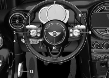
Steering wheel Information WARNING Steering wheel adjustments while driving can lead to unexpected steering wheel move‐ ments. Vehicle control could be lost. There is risk of an accident. Adjust the steering wheel while the vehicle is stationary only.◀
Adjusting
1. Switch on the ignition. 2. Fold the lever down. 3. Move the steering wheel to the preferred height and angle to suit your seating posi‐ tion.
4. Fold the lever back. 5. Switch off the ignition again if needed.
Online Edition for Part no. 01 40 2 964 625 - X/15
57
CONTROLS
Transporting children safely
Transporting children safely Vehicle features and op‐ tions This chapter describes all standard, country- specific and optional features offered with the series. It also describes features that are not
necessarily available in your car, e. g., due to the selected options or country versions. This also applies to safety-related functions and sys‐ tems. The respectively applicable country provi‐ sions must be observed when using the respec‐ tive features and systems.
The right place for children Information WARNING Unattended children or animals can move the vehicle and endanger themselves and traf‐ fic, for example with the following actions: ▷ Pressing the Start/Stop button. ▷ Releasing the parking brake. ▷ Opening and closing of doors or windows. ▷ Engaging selector lever position N. ▷ Using vehicle equipment. There is risk of accidents or injuries. Do not leave children or animals unattended in the ve‐ hicle. Carry remote control along when exiting and lock the vehicle.◀
Children should always be in the rear
WARNING Children shorter than 5 ft, 150 cm cannot correctly fasten the safety belt without suitable additional restraint systems. The protective ef‐ fect of the safety belts can be limited or lost when safety belts are fastened incorrectly. An incorrectly fastened safety belt can cause addi‐ tional injuries, for example in the event of an accident or during braking and evasive maneu‐ vers. There is risk of injuries or danger to life. Secure persons shorter than 5 ft, 150 cm using suitable restraint systems.◀
Accident research shows that the safest place for children is in the rear seat. Only transport children younger than 13 years of age or shorter than 5 ft, 150 cm in the rear in suitable child restraint systems provided in ac‐ cordance with the age, weight and size of the child. Children 13 years of age or older must wear a safety belt as soon as a suitable child restraint system can no longer be used due to their age, weight and size. Children on the front passenger seat Before using a child restraint system on the front passenger seat, ensure that the front, knee, and side airbags on the front passenger side are deactivated. Automatic deactivation of front-seat passenger airbags, refer to page 102. Information WARNING Active front-seat passenger airbags can injure a child in a child restraint system when the airbags are activated. There is risk of inju‐ ries. Make sure that the front-seat passenger airbags are deactivated and that the PASSEN‐ GER AIRBAG OFF indicator lamp lights up.◀
58
Online Edition for Part no. 01 40 2 964 625 - X/15
Transporting children safely
CONTROLS
On the front passenger seat Deactivating airbags
WARNING Active front-seat passenger airbags can injure a child in a child restraint system when the airbags are activated. There is risk of inju‐ ries. Make sure that the front-seat passenger airbags are deactivated and that the PASSEN‐ GER AIRBAG OFF indicator lamp lights up.◀ After installing a child restraint system in the front passenger seat, make sure that the front, knee and side airbags on the front passenger side are deactivated. Deactivate the front-seat passenger airbags au‐ tomatically, refer to page 102. Seat position and height Before installing a child restraint system, move the front passenger seat as far back as possible and adjust its height to the highest and thus best possible position for the belt and to offer optimal protection in the event of an accident. If the upper anchorage of the safety belt is lo‐ cated in front of the belt guide of the child seat, move the passenger seat carefully forward until the best possible belt guide position is reached. Child seat security
WARNING The stability of the child restraint system is limited or compromised with incorrect seat adjustment or improper installation of the child seat. There is risk of injuries or danger to life. Make sure that the child restraint system fits securely against the backrest. If possible, adjust the backrest tilt for all affected backrests and correctly adjust the seats. Make sure that seats and backrests are securely engaged. If possible, adjust the height of the head restraints or re‐ move them.◀
Installing child re‐ straint systems Information Pay attention to the specifications of the child restraint system manufacturer when selecting, installing, and using child restraint systems.
WARNING The stability of the child restraint system is limited or compromised with incorrect seat adjustment or improper installation of the child seat. There is risk of injuries or danger to life. Make sure that the child restraint system fits securely against the backrest. If possible, adjust the backrest tilt for all affected backrests and correctly adjust the seats. Make sure that seats and backrests are securely engaged. If possible, adjust the height of the head restraints or re‐ move them.◀ In order to faciliate the installation of a back- facing child restraint system in the rear: Move the front passenger's seat as far up as possible before folding down the backrest.
The rear safety belts and the front passenger safety belt can be permanently locked to fasten child restraint systems.
Online Edition for Part no. 01 40 2 964 625 - X/15
59
CONTROLS
Transporting children safely
Locking the safety belt 1. Pull out the strap completely. 2. Secure the child restraint system with the
belt.
3. Allow the strap to be pulled in and pull it
tight against the child restraint system. The safety belt is locked.
Unlocking the safety belt 1. Unbuckle the belt buckle. 2. Remove the child restraint system. 3. Allow the strap to be pulled in completely.
LATCH child restraint system Information LATCH: Lower Anchors and Tether for Children. Pay attention to the operating and safety infor‐ mation of the child restraint system manufac‐ turer when installing and using LATCH child re‐ straint fixing systems. Mounts for the lower LATCH anchors The lower anchors may be used to attach the CRS to the vehicle seat up to a combined child and CRS weight of 65 lb/30 kg when the child is restrained by the internal harnesses. Information WARNING If the LATCH child restraint fixing systems are not correctly engaged, the protective effect of the LATCH child restraint fixing system can be limited. There is risk of injuries or danger to life. Make sure that the lower anchors are se‐ curely engaged and that the LATCH child re‐ straint fixing system fits securely against the backrest.◀
Position
The corresponding symbol shows the mounts for the lower LATCH anchors. Seats equipped with lower anchors are marked with a pair, 2, of LATCH sym‐ bols. It is not recommended to use the inner lower anchors of standard outer LATCH positions to fasten a child restraint sys‐
tem on the middle seat. Use the vehicle seat belt instead for the middle seat.
Before installing LATCH child restraint systems Pull the belt away from the area of the child re‐ straint system. Assembly of LATCH child restraint systems 1.
Install child restraint system, see manufac‐ turer's information.
2. Ensure that both LATCH anchors are prop‐
erly connected.
Child restraint fixing system with a tether strap Information CAUTION The mounting points for the upper retain‐
ing straps of child restraint systems are only provided for these retaining straps. When other objects are mounted, the anchors can be dam‐ aged. There is risk of property damage. Only mount child restraint systems to the upper re‐ taining straps.◀
Mounting points
The respective symbol shows the an‐ chor for the upper retaining strap. Seats with an upper Top Tether are marked
60
Online Edition for Part no. 01 40 2 964 625 - X/15
Transporting children safely
CONTROLS
with this symbol. It can be found on the rear seat backrest or the rear window shelf.
Retaining strap guide
WARNING If the upper retaining strap is incorrectly used for the child restraint system, the protec‐ tive effect can be reduced. There is risk of inju‐ ries. Make sure that the upper retaining strap is not guided across sharp edges and without twisting to the upper retaining strap.◀
tem on the front passenger seat. There is risk of injuries or danger to life. With a mounted child restraint system, do not carry any people on the rear seat behind the front passenger seat.◀
WARNING If the rear backrest is not locked, the pro‐ tective effect of the child restraint system is lim‐ ited or there is none. In particular situations, for example braking maneuvers or in case of an accident, the rear backrest can fold forward. There is risk of injuries or danger to life. Make sure that the rear backrests are locked.◀
ON 5-door models: Lock‐ ing the doors and win‐ dows Doors
Push the locking lever on the rear doors up. The door can now be opened from the outside only.
Safety switch for the rear
Press button on the driver's door if children are being transported in the
rear. This locks various functions so that they cannot be operated from the rear: safety switch, refer to page 46.
1 Direction of travel 2 Head restraint 3 Hook for upper retaining strap 4 Mounting point 5 Seat backrest 6 Upper retaining strap
Attaching the upper retaining strap to the mounting point 1. Raise the head restraint if needed. 2. Guide the upper retaining strap between
the supports of the head restraint.
3. Attach the hook of the retaining strap to
the anchor on the back seat.
4. Tighten the retaining strap by pulling it
down.
WARNING In case of an accident, people sitting in the back can come into contact with the tight‐ ened retaining strap of the child restraint sys‐
Online Edition for Part no. 01 40 2 964 625 - X/15
61
CONTROLS
Driving
Driving Vehicle features and op‐ tions This chapter describes all standard, country- specific and optional features offered with the series. It also describes features that are not necessarily available in your car, e. g., due to the selected options or country versions. This also applies to safety-related functions and sys‐ tems. The respectively applicable country provi‐ sions must be observed when using the respec‐ tive features and systems.
Start/Stop button The concept
Pressing the Start/Stop button switches the ignition on or off and starts the engine. Steptronic transmission: the en‐ gine starts in selector lever posi‐ tion P or N with the brake pedal pressed when you press the Start/Stop button. Manual transmission: the engine starts with the clutch pedal pressed when the Start/Stop but‐ ton is pressed.
Ignition on Manual transmission: press the Start/Stop but‐ ton without stepping on the clutch pedal. Steptronic transmission: press the Start/Stop button, and do not press on the brake pedal at the same time. All vehicle systems are ready for operation. Most of the indicator and warning lights in the instrument cluster light up for a varied length of time.
To save battery power when the engine is off, switch off the ignition and any unnecessary electronic systems/power consumers. Ignition off Manual transmission: press the Start/Stop but‐ ton again without stepping on the clutch pedal. Steptronic transmission: shift to selector lever position P, press the Start/Stop button again without stepping on the brake. All indicator lights in the instrument cluster go out. To save battery power when the engine is off, switch off the ignition and any unnecessary electronic systems/power consumers. The ignition is switched off automatically in the following situations while the vehicle is station‐ ary and the engine is off: ▷ During locking, also with the low beams ac‐
tivated.
▷ Shortly before the battery is discharged
completely, so that the engine can still be started. This function is only available when the low beams are turned off.
▷ When opening and closing the driver door, if the driver's safety belt is unbuckled and the low beams are turned off.
▷ While the driver's safety belt is unbuckled with driver's door open and low beams off. ▷ The low beams switch to parking lights af‐
ter approx. 15 minutes of no use.
Radio ready state Activate radio-ready state: when the engine is running: press the Start/Stop button. Some electronic systems/power consumers re‐ main ready for operation. The radio-ready state is switched off automati‐ cally in the following situations:
62
Online Edition for Part no. 01 40 2 964 625 - X/15
▷ After approx. 8 minutes. ▷ When the vehicle is locked using the central
locking system.
▷ Shortly before the battery is discharged
completely, so that the engine can still be started.
The radio-ready state remains active if, for ex‐ ample, the ignition is automatically switched off for the following reasons: ▷ Opening or closing the driver's door. ▷ Unfastening of the driver's safety belt. ▷ When automatically switching from low
beams to parking lights.
If the engine is switched off and the ignition is switched on, the system automatically switches to the radio-ready state if the lights are turned off or, if correspondingly equipped, the day‐ time running lights are activated.
Starting the engine Information DANGER If the exhaust pipe is blocked or ventila‐ tion is insufficient, harmful exhaust gases can enter into the vehicle. The exhaust gases con‐ tain carbon monoxide, an odorless and color‐ less but highly toxic gas. In enclosed areas, ex‐ haust gases can also accumulate outside of the vehicle. There is danger to life. Keep the ex‐ haust pipe free and ensure sufficient ventila‐ tion.◀
WARNING An unsecured vehicle can put itself into motion and roll away. There is risk of an acci‐ dent. Before exiting, secure the vehicle against rolling. In order to ensure that the vehicle is secured against rolling away, observe the following: ▷ Set the parking brake.
Driving
CONTROLS
▷ On uphill grades or on a slope, turn the front wheels in the direction of the curb.
▷ On uphill grades or on a slope, also secure
the vehicle, for example with a wheel chock.◀
CAUTION In the case of repeated starting attempts
or repeated starting in quick succession, the fuel is not burned or is inadequately burned. The catalytic converter can overheat. There is risk of property damage. Avoid repeated start‐ ing in quick succession.◀
Steptronic transmission Starting the engine 1. Depress the brake pedal. 2. Engage selector lever position P or N. 3. Press the Start/Stop button. The ignition is activated automatically for a cer‐ tain time and is stopped as soon as the engine starts. Manual transmission Starting the engine 1. Depress the brake pedal. 2. Press on the clutch pedal and shift to neu‐
tral.
3. Press the Start/Stop button. The ignition is activated automatically for a cer‐ tain time and is stopped as soon as the engine starts.
Engine stop Information WARNING Unattended children or animals can move the vehicle and endanger themselves and traf‐ fic, for example with the following actions:
Online Edition for Part no. 01 40 2 964 625 - X/15
63
CONTROLS
Driving
▷ Pressing the Start/Stop button. ▷ Releasing the parking brake. ▷ Opening and closing of doors or windows. ▷ Engaging selector lever position N. ▷ Using vehicle equipment. There is risk of accidents or injuries. Do not leave children or animals unattended in the ve‐ hicle. Carry remote control along when exiting and lock the vehicle.◀
WARNING An unsecured vehicle can put itself into motion and roll away. There is risk of an acci‐ dent. Before exiting, secure the vehicle against rolling. In order to ensure that the vehicle is secured against rolling away, observe the following: ▷ Set the parking brake. ▷ On uphill grades or on a slope, turn the front wheels in the direction of the curb.
▷ On uphill grades or on a slope, also secure
the vehicle, for example with a wheel chock.◀
Before driving into a car wash So that the vehicle can roll into a car wash ob‐ serve instructions for going into an automatic car wash, refer to page 221. Steptronic transmission Switching off the engine 1. Engage selector lever position P with the
vehicle stopped.
2. Press the Start/Stop button. The engine is switched off. The radio-ready state is switched on.
3. Set the parking brake.
Manual transmission Switching off the engine 1. With the vehicle at a standstill, press the
Start/Stop button. The engine is switched off. The radio-ready state is switched on.
2. Shift into first gear or reverse. 3. Set the parking brake.
Auto Start/Stop function The concept The Auto Start/Stop function helps save fuel. The system switches off the engine during a stop, for example, in traffic congestion or at traffic lights. The ignition remains switched on. The engine starts again automatically for driv‐ ing off. Information After every start of the engine using the Start/ Stop button, the Auto Start/Stop function is in the last selected state, refer to page 66. When the Auto Start/Stop function is active, it is avail‐ able when the vehicle is traveling faster than about 3 mph, approx. 5 km/h. Depending on the selected driving mode, refer to page 118, the system is automatically acti‐ vated or deactivated. Engine stop The engine is switched off automatically during a stop under the following conditions: Manual transmission: ▷ Neutral is engaged and the clutch pedal is
not pressed.
▷ The driver's safety belt is buckled or the
driver's door is closed.
Steptronic transmission:
64
Online Edition for Part no. 01 40 2 964 625 - X/15
▷ The selector lever is in selector lever posi‐
tion D.
▷ Brake pedal remains depressed while the
vehicle is stopped.
▷ The driver's safety belt is buckled or the
driver's door is closed.
In order to be able to release the brake pedal, engage lever in position P. The engine remains off. To continue driving depress the brake pedal. When a gear is engaged, the engine starts au‐ tomatically. The air flow from the air conditioner is reduced when the engine is switched off. Displays in the instrument cluster
The display indicates that the Auto Start/Stop function is ready for an Automatic engine start.
The display indicates that the conditions for an automatic en‐ gine stop have not been met.
Functional limitations The engine is not switched off automatically in the following situations: ▷ External temperature too low. ▷ The external temperature is high and auto‐
matic climate control is running.
▷ The car's interior has not yet been heated
or cooled to the required level.
▷ The engine is not yet at operating tempera‐
ture.
▷ The wheels are at a sharp angle or the
steering wheel is being turned.
▷ After driving in reverse.
Driving
CONTROLS
▷ Fogging of the windows when the auto‐
matic climate control is switched on. ▷ The vehicle battery charge is very low. ▷ At higher elevations. ▷ The engine compartment lid is unlocked. ▷ The parking assistant is activated. ▷ Stop-and-go traffic. ▷ Selector lever in selector lever position R, N
or M/S.
Starting the engine The engine starts automatically under the fol‐ lowing conditions: ▷ Manual transmission:
The clutch pedal is pressed.
▷ Steptronic transmission:
By releasing the brake pedal.
After the engine starts, accelerate as usual. Safety mode After the engine switches off automatically, it will not start again automatically if any one of the following conditions are met: ▷ The driver's safety belt is unbuckled and
the driver's door is open. ▷ The hood was unlocked. Some indicator lights light up for a varied length of time. The engine can only be started via the Start/ Stop button. Functional limitations Even if driving off was not intended, the deacti‐ vated engine starts up automatically in the fol‐ lowing situations: ▷ Excessive warming of the car's interior
when the cooling function is switched on.
▷ The steering wheel is turned. ▷ Steptronic transmission: change from selec‐
tor lever position D to R, N or M/S.
Online Edition for Part no. 01 40 2 964 625 - X/15
65
CONTROLS
Driving
▷ Steptronic transmission: change from selec‐
tor lever position P to R, N, D or M/S.
▷ The vehicle begins rolling. ▷ Fogging of the windows when the auto‐
matic climate control is switched on. ▷ The vehicle battery charge is very low. ▷ Excessive cooling of the car's interior when
the heating is switched on.
▷ Manual transmission: low brake vacuum
pressure; this can occur, for example, if the brake pedal is depressed a number of times in succession.
Switching the system on/off Using the button
Press button.
▷ LED comes on: Auto Start/Stop function is
deactivated. The engine is started during an automatic engine stop. The engine can only be stopped or started via the Start/Stop button.
▷ LED goes out: Auto Start/Stop function is
activated.
Switching off the vehicle during an automatic engine stop During an automatic engine stop, the vehicle can be switched off permanently, e. g., when leaving it.
Steptronic transmission: 1. Engage selector lever position P. 2. Press the Start/Stop button. The ignition is
switched off. The Auto Start/Stop function is deactivated.
3. Set the parking brake. Manual transmission: 1. Press the Start/Stop button. The ignition is
switched off. The Auto Start/Stop function is deactivated.
2. Shift into first gear or reverse. 3. Set the parking brake. Engine start as usual via Start/Stop button. Automatic deactivation In certain situations, the Auto Start/Stop func‐ tion is deactivated automatically for safety rea‐ sons, as it is detected that no driver is present. Malfunction The Auto Start/Stop function no longer switches off the engine automatically. A Check Control message is displayed. It is possible to continue driving. Have the system checked by a dealer’s service center or another qualified service cen‐ ter or repair shop.
Parking brake Information WARNING An unsecured vehicle can put itself into motion and roll away. There is risk of an acci‐ dent. Before exiting, secure the vehicle against rolling. In order to ensure that the vehicle is secured against rolling away, observe the following: ▷ Set the parking brake. ▷ On uphill grades or on a slope, turn the front wheels in the direction of the curb.
66
Online Edition for Part no. 01 40 2 964 625 - X/15
▷ On uphill grades or on a slope, also secure
the vehicle, for example with a wheel chock.◀ Applying The lever automatically engages after being pulled up.
The indicator lamp lights up red. The parking brake is set. Lower lamp: indicator lamp in Canadian models
If for once use during driving is required, en‐ gage the parking brake slightly and hold the button down. To prevent corrosion and one-sided brake ac‐ tion, lightly apply the parking brake periodically while coasting, if traffic conditions permit. The brake lights will not light up if the parking brake is set. Releasing
Raise lever slightly, press the button and guide the lever down.
Driving
CONTROLS
Turn signal, high beams, headlight flasher Turn signal Using turn signals
Press the lever beyond the resistance point. The turn signal lever returns into is starting po‐ sition after actuation. To switch off manually, slightly tap the lever to the resistance point.
"Settings"
Triple turn signal activation Slightly tap lever. The turn signal flashes three times. The function can be activated or deactivated. On the Control Display: 1. 2. "Lighting" 3. "Triple turn signal" Settings are stored for the profile currently used. Signaling briefly Press the lever to the resistance point and hold it there for as long as you want the turn signal to flash. Malfunction Unusually rapid flashing of the indicator lamp indicates that a turn signal bulb has failed.
Online Edition for Part no. 01 40 2 964 625 - X/15
67
CONTROLS
Driving
High beams, headlight flasher
Switching on
▷ High beams, arrow 1. ▷ Headlight flasher, arrow 2.
Washer/wiper system Switching the wipers on/off and brief wipe General information Do not use the wipers if the windshield is dry, as this may damage the wiper blades or cause them to become worn more quickly. Information WARNING If the wipers start moving in the folded
away state, body parts can be jammed or dam‐ age may occur to parts of the vehicle. There is risk of injuries or risk of property damage. Make sure that the vehicle is switched off when the wipers are in the folded away state and the wipers are folded in when switching on.◀
CAUTION If the wipers are frozen to the windshield, the wiper blades can be torn off and the wiper motor overheat on switching on. There is risk of property damage. Defrost the windshield prior to switching the wipers on.◀
The lever automatically returns to its initial po‐ sition when released. ▷ Normal wiper speed: tap up once.
The wipers switch to intermittent operation when the vehicle is stationary.
▷ Fast wiper speed: tap up twice or tap once
beyond the resistance point. Wipers change to normal speed when vehi‐ cle comes to standstill.
Switching off and brief wipe
The lever automatically returns to its initial po‐ sition when released. ▷ Single wipe: press down once. ▷ To switch off from normal wiper speed:
press down once.
▷ To switch off from fast wiper speed: press
down twice.
68
Online Edition for Part no. 01 40 2 964 625 - X/15
Interval mode or rain sensor The concept Without the rain sensor, the frequency of the wiper operation is preset. The rain sensor automatically controls the time between wipes depending on the intensity of the rainfall. The sensor is located on the wind‐ shield, directly behind the interior mirror. Activating/deactivating
Press button on the wiper lever. Wiping is started. If the vehicle is equipped with a rain sensor: LED in wiper lever lights up. When wipers are frozen to windshield, wiper operation is deactivated.
CAUTION If the rain sensor is activated, the wipers
can accidentally start moving in car washes. There is risk of property damage. Deactivate the rain sensor in car washes.◀
Driving
CONTROLS
Setting the frequency or sensitivity of the rain sensor
Turn the thumbwheel to adjust the frequency or sensitivity of the rain sensor. Up: short interval or high sensitivity of the rain sensor. Down: long interval or low sensitivity of the rain sensor.
Washing the windshield
Pull the wiper lever towards you. The system sprays washer fluid on the wind‐ shield and activates the wipers briefly.
WARNING The washer fluid can freeze onto the win‐
dow at low temperatures and obstruct the view. There is risk of an accident. Only use the washer systems, if the washer fluid cannot freeze. Use antifreeze if needed.◀
CAUTION When the wiper water container is empty,
the wash pump cannot work as intended. There is risk of property damage. Do not use
Online Edition for Part no. 01 40 2 964 625 - X/15
69
CONTROLS
Driving
the washer system when the wash water con‐ tainer is empty.◀
Windshield washer nozzles The windshield washer nozzles are automati‐ cally heated while the ignition is switched on. Rear window wiper Switching on the rear window wiper
Turn the switch from idle position 0 upward, ar‐ row 1: interval mode. When reverse gear is en‐ gaged, the system switches to continuous op‐ eration.
Cleaning rear window In interval mode: turn the switch further, ar‐ row 2. The switch automatically returns to its interval position when released. In idle position: turn switch downward, arrow 3. The switch automatically returns to its idle posi‐ tion when released. Fold-out position of the wipers Helpful when changing the wiper blades or un‐ der frosty conditions, for example.
WARNING If the wipers start moving in the folded
away state, body parts can be jammed or dam‐ age may occur to parts of the vehicle. There is risk of injuries or risk of property damage. Make sure that the vehicle is switched off when the
wipers are in the folded away state and the wipers are folded in when switching on.◀ 1. Switch the ignition on and off again. 2. With icy conditions make sure that blades
are not frozen to the windshield.
3. Press the wiper lever up beyond the point of resistance and hold it for approx. 3 sec‐ onds, until the wiper remains in a nearly vertical position.
After the wipers are folded back down, the wiper system must be reactivated. 1. Switch on the ignition. 2. Push wiper lever down. Wipers return to their resting position and are ready again for operation.
Washer fluid General information All washer nozzles are supplied from one reser‐ voir. Prepare and dilute a mixture of tap water, windshield washer concentrate, and possibly antifreeze prior to filling. Recommended minimum fill quantity: 0.2 US gal/1 liter. Information WARNING Some antifreeze agents can contain
harmful substances and are flammable. There is risk of fire and risk of injuries. Observe the in‐ structions on the containers. Keep antifreeze away from ignition sources. Do not refill oper‐ ating materials into different bottles. Store op‐ erating materials out of reach of children. United States: The washer fluid mixture ratio is regulated by the U.S. EPA and many individual states; do not exceed the allowable washer fluid dilution ratio limits that apply. Follow the
70
Online Edition for Part no. 01 40 2 964 625 - X/15
usage instructions on the washer fluid con‐ tainer. Use of BMW’s Windshield Washer Concentrate or the equivalent is recommended.◀
WARNING Washer fluid can ignite and catch fire on contact with hot engine parts. There is risk of injuries or risk of property damage. Only add washer fluid when the engine is cooled down. Next, fully close the lid of the washer fluid res‐ ervoir.◀
CAUTION Silicon-containing additives in the washer fluid for the water-repelling effect on the win‐ dows can lead to damage to the washing sys‐ tem. There is risk of property damage. Do not add silicon-containing additives to the washer fluid.◀
CAUTION The use of undiluted and different wind‐
shield washer concentrate or antifreeze can lead to damage to the washing system. There is risk of property damage. Dilute windshield washer concentrate or antifreeze prior to filling. Observe the information and mixing ratios pro‐ vided on the containers. Do not mix windshield washer concentrates of different manufactur‐ ers.◀
Overview
Driving
CONTROLS
Manual transmission Information CAUTION When shifting to a lower gear, excessive speeds can damage the engine. There is risk of property damage. When shifting into 5th or 6th gear, press the gearshift lever to the right.◀
WARNING An unsecured vehicle can put itself into motion and roll away. There is risk of an acci‐ dent. Before exiting, secure the vehicle against rolling. In order to ensure that the vehicle is secured against rolling away, observe the following: ▷ Set the parking brake. ▷ On uphill grades or on a slope, turn the front wheels in the direction of the curb.
▷ On uphill grades or on a slope, also secure
the vehicle, for example with a wheel chock.◀
Shifting General information The engine speed during a shifting operation is adjusted automatically for harmonious and dy‐ namic gear shifting. Reverse gear Select only when the vehicle is stationary. To overcome the resistance push the selector lever dynamically to the left and engage the re‐ verse gear.
The washer fluid reservoir is located in the en‐ gine compartment.
Online Edition for Part no. 01 40 2 964 625 - X/15
71
yond the resistance point at the full throttle po‐ sition. Engaging selector lever positions To prevent the vehicle from creeping after you select a gear, maintain pressure on the brake pedal until you are ready to start. The selector lever can only be taken out of se‐ lector lever position P if the ignition is on or the engine is running. With the vehicle stationary, depress the brake pedal before shifting out of selector lever posi‐ tion P or N; otherwise, the shift block will not be deactivated and the shift command will not be executed. A block prevents the inadvertent switching to selector lever position P or R or the inadvertent change from selector lever position P. Canceling the lock
Press unlock button on the front of the selector lever, arrow.
CONTROLS
Driving
Steptronic transmission Information WARNING An unsecured vehicle can put itself into motion and roll away. There is risk of an acci‐ dent. Before exiting, secure the vehicle against rolling. In order to ensure that the vehicle is secured against rolling away, observe the following: ▷ Set the parking brake. ▷ On uphill grades or on a slope, turn the front wheels in the direction of the curb.
▷ On uphill grades or on a slope, also secure
the vehicle, for example with a wheel chock.◀
Selector lever positions D Drive Selector lever position for normal vehicle oper‐ ation. All gears for forward travel are activated automatically. R Reverse Select only when the vehicle is stationary. N Neutral The vehicle may roll. Use in automatic car washes, for example. P Park Select only when the vehicle is stationary. The drive wheels are blocked. Before exiting the vehicle, make sure that se‐ lector lever position P is set. Otherwise, the ve‐ hicle may begin to move. Kickdown Kickdown is used to achieve maximum driving performance. Step on the accelerator pedal be‐
72
Online Edition for Part no. 01 40 2 964 625 - X/15
Sport program and manual mode M/S Activating the sport program
Press the selector lever to the left out of selec‐ tor lever position D. The engaged gear is displayed in the instru‐ ment cluster, for example, S1. The sport program of the transmission is acti‐ vated.
Activating the M/S manual mode 1. Press the selector lever to the left out of se‐
lector lever position D.
2. Push the selector lever forward or back‐
ward.
Manual mode M/S becomes active and the gear is changed. The engaged gear is displayed in the instru‐ ment cluster, for example, M1. If the situation requires, the Steptronic trans‐ mission continues to shift automatically. Example: once maximum engine speed is at‐ tained, M/S manual mode is automatically up‐ shifted as needed. Switching to manual mode ▷ To shift down: press the selector lever for‐
ward.
▷ To shift up: pull the selector lever rear‐
wards.
Gears will only be shifted at appropriate engine and road speeds, for example downshifting is not possible if the engine speed is too high.
Driving
CONTROLS
The selected gear is briefly displayed in the in‐ strument cluster, followed by the currently se‐ lected gear. Manual mode M/S: prevent automatic upshifting Once a particular engine speed is attained, M/S manual mode is automatically upshifted as needed. For vehicles with Steptronic Sport transmission, automatic shift operations are not performed if one of the following conditions is met: ▷ DSC is deactivated. ▷ TRACTION is activated. In addition, there is no downshifting for kick‐ down. With the respective transmission version, the lowest possible gear can be selected by simul‐ taneously operating the kickdown and the left shift paddle. This is not possible, when switch‐ ing briefly via the shift paddles from selector lever position D to manual mode M/S. Ending the sport program/manual mode Push the selector lever to the right. D is displayed in the instrument cluster. Shift paddles for Steptronic Sport transmission
The shift paddles on the steering wheel allow you to shift gears quickly while keeping both hands on the steering wheel. ▷ Shift up: briefly pull right shift paddle.
Online Edition for Part no. 01 40 2 964 625 - X/15
73