- Download PDF Manual
-
CONTROLS
Driving
▷ Shift down: briefly pull left shift paddle. ▷ The lowest possible gear can be selected by
pulling and holding the left shift paddle.
Gears will only be shifted at appropriate engine and road speeds, for example downshifting is not possible if the engine speed is too high. The selected gear is briefly displayed in the in‐ strument cluster, followed by the current gear. If the shift paddles on the steering wheel are used to shift gears in automatic mode, the transmission temporarily switches to manual mode. In the manual mode, after conservative driving for a certain amount of time or if there has been no acceleration or shifting of the shift paddles within a certain amount of time, the transmission switches back to automatic mode. It is possible to switch into the automatic mode: ▷ Pull and hold right shift paddle.
or
▷ In addition to the briefly pulled right shift
paddle, briefly pull the left shift paddle.
Displays in the instrument cluster
The selector lever position is dis‐ played, for example: P.
Manually release the transmission lock Should the selector lever be blocked in selector lever position P despite the ignition being turned on, the brake being depressed and the unlock button being pressed, the transmission lock can be manually canceled: Before unlocking the transmission lock man‐ ually, engage the parking brake forcefully to prevent the vehicle from rolling away. 1. Loosen the selector lever sleeve together with the lower retaining ring and possibly the Driving Dynamics Control from the cen‐
ter console. For this purpose, pull the re‐ taining ring and possibly the Driving Dy‐ namics Control upward on the rear edge.
2. Lift the sleeve. Unplug the cable connector
if needed.
3. Using the screwdriver from the onboard ve‐
hicle tool kit, refer to page 204, press the yellow release lever downward, arrow.
4. Move the selector lever slightly toward the rear; to do this press the unlock button on the front of the selector lever. Release the release lever.
5. Bring the selector lever into the desired po‐
sition.
Steptronic Sport transmission: Launch Control The concept Launch Control enables optimum acceleration on surfaces with good traction.
74
Online Edition for Part no. 01 40 2 964 625 - X/15
Driving
CONTROLS
General information The use of Launch Control causes premature component wear since this function represents a very heavy load for the vehicle. Do not use Launch Control during the break-in, refer to page 160, period. To increase vehicle stability, activate DSC again as soon as possible. An experienced driver may be able to achieve better acceleration values in DSC OFF mode, re‐ fer to page 116. Requirements Launch Control is available when the engine is warmed up, that is, after uninterrupted driving of at least 6 miles/10 km. To start with Launch Control do not steer the steering wheel. Start with launch control While the engine is running:
1.
Press button and select SPORT with
Driving Dynamics Control, refer to page 118. The instrument cluster displays TRACTION in combination with SPORT. The DSC OFF indicator lamp lights up.
2. Engage selector lever position S. 3. With the left foot, forcefully press down on
the brake.
4. Step on the accelerator pedal beyond the resistance point at the full throttle position, kickdown. A flag symbol is displayed in the instrument cluster.
5. The starting engine speed adjusts. Within
3 seconds, release the brake.
Before using Launch Control, allow the trans‐ mission to cool down for approx. 5 minutes.
Online Edition for Part no. 01 40 2 964 625 - X/15
75
CONTROLS
Displays
Displays Vehicle features and op‐ tions This chapter describes all standard, country- specific and optional features offered with the series. It also describes features that are not
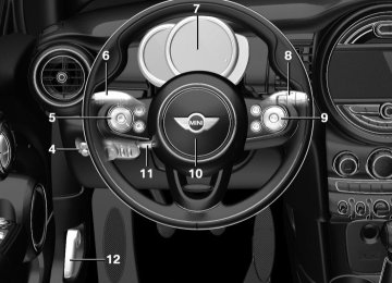
Instrument cluster Overview, instrument cluster
necessarily available in your car, e. g., due to the selected options or country versions. This also applies to safety-related functions and sys‐ tems. The respectively applicable country provi‐ sions must be observed when using the respec‐ tive features and systems.
1 Tachometer 81
2 Indicator/warning lights 3 Speedometer4 Fuel gauge 81
5 Display/reset miles 81
6 Electronic displays 7776
Online Edition for Part no. 01 40 2 964 625 - X/15
Displays
CONTROLS
Electronic displays
1 Driver assistance systems
Messages, e.g., Check Control Time 81
External temperature 81
Selection lists 85
Total miles/trip odometer 81On-board computer 85
2 Selector lever position display 72
Gear shift indicator 83
3 Driving Dynamics Control 118
Status
Check Control The concept The Check Control system monitors functions in the vehicle and notifies you of malfunctions in the monitored systems. A Check Control message is displayed as a com‐ bination of indicator or warning lights and text messages in the instrument cluster and in the Head-up Display. In addition, an acoustic signal may be output and a text message may appear on the Control Display.
Indicator/warning lights General information The indicator and warning lights can light up in a variety of combinations and colors. Several of the lights are checked for proper functioning and light up temporarily when the engine is started or the ignition is switched on. Red lights Safety belt reminder
Flashing or illuminated: safety belt on the driver or passenger side is not buck‐ led. The safety belt reminder can also
Online Edition for Part no. 01 40 2 964 625 - X/15
77
CONTROLS
Displays
be activated if objects are placed on the front passenger seat. Make sure that the safety belts are positioned correctly.
Airbag system
Airbag system and belt tensioner are not working. Have the vehicle checked immediately by a dealer’s service center or another qualified service center or repair shop.
Parking brake, brake system The parking brake is set. For additional information, refer to Re‐ lease parking brake, refer to page 67.
Front-end collision warning
Illuminated: advance warning is issued, e.g., when there is the impending dan‐ ger of a collision or the distance to the
vehicle ahead is too small. Increase distance. Flashing: acute warning of the imminent dan‐ ger of a collision when the vehicle approaches another vehicle at a relatively high differential speed. Intervention by braking or make an evasive maneuver.
Pedestrian warning
If a collision with a person detected in this way is imminent, the symbol lights up and a signal sounds.
Orange lights Active Cruise Control
The number bars shows the selected distance from the vehicle driving ahead. For more information, see Camera-
based cruise control, refer to page 120.
Vehicle detection, Active Cruise Control
Illuminated: vehicle driving ahead de‐ tected. Flashing: the conditions are not ade‐
quate for operating the system. The system was deactivated but applies the brakes until you actively resume control by pressing on the brake pedal or accelerator pedal.
Yellow lights Anti-lock Braking System ABS
Avoid sudden braking as much as possi‐ ble. Braking force boost may not be working. Stop cautiously. Take into ac‐ count the longer brake distance. Have the system immediately checked by a dealer’s service center or another quali‐
fied service center or repair shop.
DSC Dynamic Stability Control
Flashing: DSC controls the drive and braking forces. The vehicle is stabilized. Reduce speed and adapt driving style to
the driving circumstances. Illuminated: DSC failed. Have the system checked by a dealer’s service center or another qualified service center or repair shop. For additional information, refer to Dynamic Stability Control DSC, refer to page 116.
78
Online Edition for Part no. 01 40 2 964 625 - X/15
Displays
CONTROLS
DSC Dynamic Stability Control is deactivated or DTC Dynamic Traction Control is activated
For additional information, refer to Tire Pres‐ sure Monitor, refer to page 103.
Dynamic Stability Control DSC is switched off or Dynamic Traction Con‐ trol DTC is switched on.
For additional information, refer to Dynamic Stability Control DSC, refer to page 116, and Dynamic Traction Control DTC, refer to page 117.
Flat Tire Monitor FTM
The Flat Tire Monitor signals a loss of tire inflation pressure in a tire. Reduce your speed and stop cautiously. Avoid sudden braking and steering maneuvers. For additional information, refer to Flat Tire Monitor, refer to page 107.
Tire Pressure Monitor TPM
Illuminated: the Tire Pressure Monitor signals a loss of tire inflation pressure in a tire.
Reduce your speed and stop cautiously. Avoid sudden braking and steering maneuvers. Flashing and then continuously illuminated: no flat tire or loss of tire inflation pressure can be detected. ▷ Interference through systems or devices
with the same radio frequency: After leav‐ ing the area of the interference, the system automatically becomes active again.
▷ TPM was unable to complete the reset. Re‐
set the system again.
▷ A wheel without TPM electronics is
mounted: Have it checked by a dealer’s service center or another qualified service center or repair shop as needed.
▷ Malfunction: have the system checked by a dealer’s service center or another qualified service center or repair shop.
Steering system
Steering system in some cases not working. Have the steering system checked by a
dealer’s service center or another qualified service center or repair shop.
Engine functions
Have the vehicle checked by a dealer’s service center or another qualified serv‐ ice center or repair shop.
For additional information, refer to On-board Diagnostics socket, refer to page 203.
Rear fog lamp
Rear fog lights are activated. For additional information, refer to Rear fog lights, refer to page 98.
Green lights Turn signal
Turn signal switched on. Unusually rapid flashing of the indicator lamp indicates that a turn signal bulb
has failed. For additional information, refer to Turn signal, refer to page 67.
Parking lights, headlight control
Parking lights or headlights are acti‐ vated. For additional information, refer to
Parking lights/low beams, headlight control, re‐ fer to page 95.
Online Edition for Part no. 01 40 2 964 625 - X/15
79
CONTROLS
Displays
Front fog lights
Front fog lights are activated. For additional information, refer to Front fog lights, refer to page 98.
High-beam Assistant
High-beam Assistant is switched on. High beams are activated and off auto‐ matically as a function of the traffic sit‐
uation. For additional information, refer to High-beam Assistant, refer to page 97.
Cruise control
The system is switched on. It maintains the speed that was set using the control elements on the steering wheel.
Blue lights High beams
High beams are activated. For additional information, refer to High beams, refer to page 68.
General lamps
At least one Check Control message is displayed or is stored.
Text messages Text messages in combination with a symbol in the instrument cluster explain a Check Control message and the meaning of the indicator and warning lights. Supplementary text messages Additional information, such as on the cause of an error or the required action, can be called up via Check Control.
With urgent messages the added text will be automatically displayed on the Control Display. Symbols Within the supplementary text, the following functions can be selected independent of the check control message. ▷
Display additional information about
the Check Control message in the Integrated Owner's Manual.
▷
▷
"Service request"
Contact a dealer’s service center or another qualified service center or repair shop.
"Roadside Assistance"
Contact Roadside Assistance.
Hiding Check Control messages
Press and hold button on turn signal lever. ▷ Some Check Control messages are dis‐ played continuously and are not cleared until the malfunction is eliminated. If sev‐ eral malfunctions occur at once, the mes‐ sages are displayed consecutively. These messages can be faded for approx. 8 seconds. After this time, they are dis‐ played again automatically.
▷ Other Check Control messages are faded automatically after approx. 20 seconds. They are stored and can be displayed again later.
80
Online Edition for Part no. 01 40 2 964 625 - X/15
Displaying stored Check Control messages On the Control Display: 1. "Vehicle info" 2. "Vehicle status" 3. 4. Select the text message. Messages after trip completion Special messages displayed while driving are displayed again after the ignition is switched off.
"Check Control"
Fuel gauge
Vehicle tilt position may cause the display to vary. The arrow beside the fuel pump symbol shows which side of the vehicle the fuel filler flap is on.
Hints on refueling, refer to page 176.
Tachometer Always avoid engine speeds in the red warning field. In this range, the fuel supply is interrupted to protect the engine.
Odometer and trip odom‐ eter The concept Odometer and trip odometer are displayed in the instrument cluster.
Displays
CONTROLS
Resetting the trip odometer
Press the knob. ▷ The odometer is displayed
when the ignition is switched off.
▷ When the ignition is switched
on, the trip odometer is re‐ set.
External temperature
If the indicator drops to +37 ℉/+3 ℃, a signal sounds. A Check Control message is dis‐ played. There is an increased risk of ice
on roads.
WARNING Even at temperatures above +37 ℉/+3 ℃ there can be a danger of icy roads, for example on bridges or shady sections of road. There is risk of an accident. Adjust your driving style to the weather conditions at low temperatures.◀
Time
Date
The time is displayed in the in‐ strument cluster. Setting the time on the Control Display, refer to page 88.
The date is displayed in the in‐ strument cluster. Set the date on the Control Dis‐ play, refer to page 88.
Online Edition for Part no. 01 40 2 964 625 - X/15
81
CONTROLS
Displays
Range Display
With a low remaining range: ▷ A Check Control message is
displayed briefly.
▷ The remaining range is
shown on the onboard com‐ puter.
▷ With a dynamic driving style, e.g. taking
curves aggressively, the engine function is not always ensured.
The Check Control message appears continu‐ ously below a range of approx. 30 miles/50 km.
CAUTION With a range of less than 30 miles/50 km it is possible that the engine will no longer have sufficient fuel. Engine functions are not ensured anymore. There is risk of property damage. Re‐ fuel promptly.◀
"Settings"
Displaying the cruising range 1. 2. "Instrument cluster" 3. "Range"
Current fuel consump‐ tion The concept Displays the current fuel consumption. Check whether you are currently driving in an efficient and environmentally-friendly manner. Displaying the current fuel consumption "Settings" 1. 2. "Instrument cluster" 3. "Current consumption"
Service requirements The concept After the ignition is turned on the instrument cluster briefly displays available driving distance or time to the next scheduled maintenance. A service advisor can read out the current serv‐ ice requirements from your remote control. Display Detailed information on service requirements More information on the scope of service re‐ quired can be displayed on the Control Display. 1. 2. "Vehicle status" 3.
"Service required"
"Vehicle info"
Required maintenance procedures and le‐ gally mandated inspections are displayed. 4. Select an entry to call up detailed informa‐
tion. Symbols
Symbols
Description No service is currently required.
The deadline for scheduled maintenance or a legally man‐ dated inspection is approach‐ ing. The service deadline has al‐ ready passed.
Entering appointment dates Enter the dates for the required inspections. Make sure that the vehicle's date and time are set correctly.
82
Online Edition for Part no. 01 40 2 964 625 - X/15
On the Control Display: 1. "Vehicle info" 2. "Vehicle status" 3. "Service required" 4. "§ Vehicle inspection" 5. "Date:" 6. Adjust the settings. 7. Confirm.
The entered date is stored.
Gear shift indicator The concept The system recommends the most fuel efficient gear for the current driving situation. General information Depending on the vehicle's features and coun‐ try version of the vehicle, the gear shift indica‐ tor is active in the manual mode of the Step‐ tronic transmission and with manual transmission. Suggestions to shift gear up or down are dis‐ played in the instrument cluster. Manual transmission: displaying
Example
Description Fuel efficient gear is set.
Shift into fuel efficient gear.
Displays
CONTROLS
Steptronic transmission: displaying
Example
Description Fuel efficient gear is set.
Shift into fuel efficient gear.
Speed limit detection The concept Speed limit detection Speed limit detection shows the current maxi‐ mum permitted speed in the instrument clus‐ ter. The camera at the base of the interior rear‐ view mirror detects traffic signs at the edge of the road as well as variable overhead sign posts. Traffic signs with extra symbols for wet road conditions, etc. are also detected and compared with the vehicle's onboard data, such as for the rain sensor, and will be dis‐ played depending on the situation. With the navigation system, the system takes into account the information stored in the navi‐ gation data and also displays speed limits present on routes without signs. Without a navigation system, the system is sub‐ ject to limitations imposed by technology. Speed limits with extra text characters are al‐ ways displayed. Information Speed limits when towing a trailer are not shown.
WARNING The system does not relieve from the per‐ sonal responsibility to correctly assess visibility and traffic situation. There is risk of an accident. Adjust the driving style to the traffic conditions.
Online Edition for Part no. 01 40 2 964 625 - X/15
83
CONTROLS
Displays
Watch traffic closely and actively interfere in the respective situations.◀
Overview Camera
The camera is installed near the interior mirror. Keep the windshield in the area behind the in‐ terior mirror clean and clear.
Display Speed limit detection is displayed via the on‐ board computer.
Press button on the turn signal lever several times if needed. Speed limit detection is displayed on the CID (central information display) in the instrument cluster.
Speed limit detection
The last speed limit detected. Without a navigation system the traffic signals are grayed out af‐ ter curves or longer stretches of roadway.
With navigation system: speed limit detection is not available.
Without navigation system: no speed limit or cancellation is de‐ tected.
Speed limit detection can also be displayed in the Head-up Display. System limits The system may not be fully functional and may provide incorrect information in the fol‐ lowing situations: ▷ In heavy fog, rain or snowfall. ▷ When signs are concealed by objects. ▷ When driving very close to the vehicle in
front of you.
▷ When driving toward bright lights. ▷ When the windshield behind the interior
mirror is fogged over, dirty or covered by a sticker, etc.
▷ In the event of incorrect detection by the
camera.
▷ If the speed limits stored in the navigation
system are incorrect.
▷ In areas not covered by the navigation sys‐
tem.
▷ When roads differ from the navigation, such
as due to changes in road routing.
▷ When passing buses or trucks with a speed
sticker.
84
Online Edition for Part no. 01 40 2 964 625 - X/15
▷ If the traffic signs are non-conforming. ▷ During calibration of the camera immedi‐
ately after vehicle delivery.
Selection lists in the in‐ strument cluster The concept With the buttons on the steering wheel and the display in the instrument cluster the following can be displayed or operated: ▷ Current audio source. ▷ Redial phone feature. ▷ Turn on voice activation system. It also displays programs of the Driving Dynam‐ ics Control. Display
Activating a list and adjusting the setting
Button the steering wheel
Function Activate the respec‐ tive list and select the desired settings.
Confirm the selection.
Displays
CONTROLS
On-board computer Calling up information on the info display
Press and hold button on blinker lever. Information is displayed in the info display of the instrument cluster.
Information at a glance Info display
Repeatedly pressing the button on the turn signal lever calls up the following information in the info display: ▷ Range.
▷ GREEN Info.
When GREEN Mode is activated.
▷ Average fuel consumption. ▷ Current fuel consumption. ▷ Average speed. ▷ Date. ▷ Engine temperature display. ▷ With equipment version with Head-up Dis‐
play and navigation: Distance to destination. When destination guidance is activated in the navigation system.
▷ With equipment version with Head-up Dis‐
play and navigation: Time of arrival.
Online Edition for Part no. 01 40 2 964 625 - X/15
85
CONTROLS
Displays
When destination guidance is activated in the navigation system. ▷ Speed limit detection. ▷ Speed.
"Settings"
Selecting information You can select what information from the on‐ board computer is to be displayed on the CID (central information display) of the instrument cluster. On the Control Display: 1. 2. "Instrument cluster" 3. Select the desired information. Settings are stored for the profile currently used. Information in detail Range Displays the estimated cruising range available with the remaining fuel. It is calculated based on your driving style over the last 20 miles/30 km. GREEN info Description of GREEN info, refer to page 169. Average fuel consumption This is calculated for the period while the en‐ gine is running. The average fuel consumption is calculated for the distance traveled since the last reset by the onboard computer. Average speed Periods in which the vehicle is parked with the engine manually stopped are not included in the calculation of the average speed.
Resetting average values
Press and hold button on turn signal lever.
Engine temperature display Displays the current engine temperature, based on a combination of coolant and motor oil tem‐ perature. As soon as the optimum operating temperature has been attained, the indicator is in the center position. If the engine oil or coolant, thus the engine, be‐ come too hot, a Check Control message is dis‐ played. Check the coolant level, refer to page 200. With equipment version with Head-up Display and navigation: distance to destination The distance remaining to the destination is displayed if a destination is entered in the navi‐ gation system before the trip is started. The distance to the destination is adopted au‐ tomatically. With equipment version with Head-up Display and navigation: time of arrival The estimated time of arrival is displayed if a destination is entered in the navigation system before the trip is started. The time must be correctly set. Speed limit detection Speed limit detection is preset. Description of the speed limit detection, refer to page 83, function.
86
Online Edition for Part no. 01 40 2 964 625 - X/15
Displays
CONTROLS
"Sports instruments"
"Driving Excitement" "Sports instruments"
Sport instruments On the Control Display, values for power and torque are displayed. Displaying sport instruments Via onboard monitor: 1. "Vehicle info" 2. "Driving Excitement" 3. Via the Driving Dynamics Control 1. Activating SPORT. 2. 3. Vehicle state The following vehicle and surrounding area data are automatically checked and evaluated in succession: ▷ Range. ▷ Engine temperature. ▷ External temperature. ▷ SPORT program state. Finally, a total evaluation of the vehicle state is displayed. Checking vehicle state Via onboard monitor: "Vehicle info" 1. 2. "Driving Excitement" 3. Via the Driving Dynamics Control 1. Activating SPORT. 2. 3.
"Driving Excitement" "Vehicle and surroundings"
"Vehicle and surroundings"
Trip onboard computer The vehicle features two types of onboard computers. ▷ "Onboard info": the values can be reset as
often as necessary.
▷ "Trip computer": the values provide an
overview of the current trip.
Resetting the trip onboard computer On the Control Display: 1. "Vehicle info" 2. "Trip computer" 3. "Reset": all values are reset.
"Automatically reset": all values are reset approx. 4 hours after the vehicle came to a standstill.
Display on the Control Display Display the onboard computer or trip onboard computer on the Control Display. On the Control Display: "Vehicle info" 1. 2. "Onboard info" or "Trip computer" Resetting the fuel consumption and speed On the Control Display: "Vehicle info" 1. 2. "Onboard info" 3. "Consumpt." or "Speed" 4. "Yes"
Driving Excitement The concept On the Control Display, sport instruments can be displayed, and the vehicle condition can be checked before the use of the SPORT program.
Online Edition for Part no. 01 40 2 964 625 - X/15
87
CONTROLS
Displays
Speed warning The concept Displays speed limit which, when reached, should cause a warning to be issued. The warning is repeated if the vehicle speed drops below the set speed limit once by at least 3 mph/5 km/h. Displaying, setting or changing the limit On the Control Display: 1. 2. "Speed" 3. "Warning at:" 4. Turn the Controller until the desired limit is
"Settings"
displayed.
"Settings"
5. Press the Controller. The speed limit is stored. Activating/deactivating the limit On the Control Display: 1. 2. "Speed" 3. "Warning" 4. Press the Controller. Setting your current speed as the limit On the Control Display: 1. 2. "Speed" 3. "Select current speed" 4. Press the Controller.
"Settings"
The current vehicle speed is stored as the limit.
Settings on the Control Display Time Setting the time zone "Settings" 1. 2. "Time/Date" 3. "Time zone:" 4. Select the desired time zone. The time zone is stored. Setting the time "Settings" 1. 2. "Time/Date" 3. "Time:" 4. Turn the Controller until the desired hours
are displayed.
5. Press the Controller. 6. Turn the Controller until the desired mi‐
nutes are displayed. 7. Press the Controller. The time is stored. Setting the time format "Settings" 1. 2. "Time/Date" 3. "Format:" 4. Select the desired format. The time format is stored. Date Setting the date "Settings" 1. 2. "Time/Date" 3. "Date:" 4. Turn the Controller until the desired day is
displayed.
88
Online Edition for Part no. 01 40 2 964 625 - X/15
5. Press the Controller. 6. Make the necessary settings for the month
and year.
"Settings"
The date is stored. Setting the date format "Settings" 1. 2. "Time/Date" 3. "Format:" 4. Select the desired format. The date format is stored. Language Setting the language To set the language on the Control Display: 1. 2. "Language/Units" 3. "Language:" 4. Select the desired language. Settings are stored for the profile currently used. Setting the voice dialog Voice dialog for the voice activation system, re‐ fer to page 27. Units of measurement Setting the units of measurement To set the units for fuel consumption, route/ distance and temperature: 1. 2. "Language/Units" 3. Select the desired menu item. 4. Select the desired unit. Settings are stored for the profile currently used.
"Settings"
Displays
CONTROLS
Brightness Setting the brightness To set the brightness of the Control Display: 1. 2. "Control display" 3. "Brightness" 4. Turn the Controller until the desired bright‐
"Settings"
ness is set.
5. Press the Controller. Settings are stored for the profile currently used. Depending on the light conditions, the bright‐ ness settings may not be clearly visible.
LED ring on the central instrument cluster The concept The LED ring displays light animations to repre‐ sent specific functions. Basic displays Basic functions, for example the tachometer, can be set to be displayed continually if so de‐ sired. Event displays Functions that are only displayed temporarily, for example the volume or temperature set‐ tings, can be set as event displays. Several vehicle assistance functions can also be displayed on the LED ring. This display corre‐ sponds with the displays of the function in the respective display. Example: tachometer Like the tachometer in the instrument cluster, the light animations of the tachometer's basic display show the current RPMs and the respec‐ tive RPM warning margins.
Online Edition for Part no. 01 40 2 964 625 - X/15
89
CONTROLS
Displays
Display
"Settings"
"Settings"
▷ Arrow 1: current RPM. ▷ Arrow 2: prewarning field. ▷ Arrow 3: warning field. Switching on/off LED ring 1. 2. "Center Instrument" 3. "Center Instrument" Adjusting the LED ring 1. 2. "Center Instrument" 3. "Basic display" or "Event display" 4. Select desired setting. Setting the brightness The brightness can be adjusted when night lighting is active in the instrument cluster. 1. 2. "Center Instrument" 3. "Brightness" 4. Turn the controller. Settings are stored for the profile currently used.
"Settings"
Head-up Display The concept This system projects important information into the driver's field of vision, e. g., the speed. The driver can quickly absorb information and concentrate on the traffic situation. Information CAUTION The Head-up Display consists of sensitive components that can easily be scraped or dam‐ aged. There is risk of property damage. Do not place any objects on the Head-up Display, at‐ tach to system components or plug into the system. Do not move the moving parts man‐ ually.◀
WARNING When extending and retracting the pro‐
jection screen of the Head-up Display, body parts can be jammed. There is risk of injuries. Make sure that the area of movement of the projection screen is clear during opening and closing.◀ Follow the instructions for cleaning the Head- up Display, refer to page 224. Overview
Display visibility The visibility of the displays in the Head-up Dis‐ play is influenced by the following factors: ▷ Certain sitting positions.
90
Online Edition for Part no. 01 40 2 964 625 - X/15
▷ Objects on the cover of the Head-up Dis‐
play.
▷ Sunglasses with certain polarization filters. ▷ Wet roads. ▷ Unfavorable light conditions. Switching on/off When switching on, the projection lens of the Head-up Display is extended. When switching off, the projection lens of the Head-up Display is retracted again.
Press button.
Display Overview The following information is displayed on the Head-up Display: ▷ Speed. ▷ Navigation system. ▷ Check Control messages. ▷ Selection list from the instrument cluster. ▷ Driver assistance systems. Some of this information is only displayed briefly as needed. Selecting displays in the Head-up Display On the Control Display: 1. 2. "Head-Up Display"
"Settings"
Displays
CONTROLS
3. "Displayed information" 4. Select the desired displays in the Head-up
Display.
Settings are stored for the profile currently used. Setting the brightness The brightness is automatically adjusted to the ambient brightness. The basic setting can be adjusted manually. On the Control Display: 1. 2. "Head-Up Display" 3. "Brightness" 4. Turn the Controller until the desired bright‐
"Settings"
ness is set.
5. Press the Controller. When the low beams are activated, the bright‐ ness of the Head-up Display can be additionally influenced using the instrument lighting, refer to page 98. Settings are stored for the profile currently used. Adjusting the height On the Control Display: 1. 2. "Head-Up Display" 3. "Height" 4. Turn the Controller until the desired height
"Settings"
is reached.
5. Press the Controller. Settings are stored for the profile currently used. Setting the rotation The screen of the Head-up Display can be ro‐ tated around its own axis.
Online Edition for Part no. 01 40 2 964 625 - X/15
91
CONTROLS
Displays
"Settings"
On the Control Display: 1. 2. "Head-Up Display" 3. "Rotation" 4. Turn the Controller until the desired setting
is selected.
5. Press the Controller. Settings are stored for the profile currently used. John Cooper Works: Sport displays in the Head-up Display General information The sport displays in the Head-up Display assist with a sporty driving style. Switching on "Settings" 1. 2. "Head-Up Display" 3. "Displayed information" 4. "Sport displays" With navigation system: if the sport displays are switched on, no navigation content will be dis‐ played on the Head-up Display. Display
1 Speed 2 Shift point indicator 3 Gear display
4 Current engine speed 5 Warning field, speed
Shift point indicator The concept Shift point indicator in the Head-up Display in‐ dicates the optimum shifting point. Thus, with a sporty driving style, the best possible vehicle acceleration is achieved.
Functional requirements ▷ Steptronic transmission:
Manual mode M/S and if necessary the Dy‐ namic Traction Control DTC are activated.
▷ Press the gas pedal all the way down.
Switching on Shift point indicators are displayed in the Head- up if the sport displays, refer to page 92,are switched on. 1. 2. "Head-Up Display" 3. "Displayed information" 4. "Sport displays"
"Settings"
Display Successive gray illuminated fields indicate the upcoming upshift moment. As soon as the red fields light up, shift up im‐ mediately. When the permitted maximum speed is reached, all shift point indicators flash. When the maximum speed is exceeded, the supply of fuel is interrupted in order to protect the engine.
92
Online Edition for Part no. 01 40 2 964 625 - X/15
Chrono package in the cockpit The concept The Chrono package consists of three display instruments in the cockpit, where the engine oil pressure, the turbocharger boost, and the time are displayed. In addition, intermediate and to‐ tal times can be measured using the stop watch. The display elements of the Chrono package mainly support a sporty driving style, e,g, on racetracks. Overview
1 Engine oil pressure display 2 Display of turbocharger boost 3 Time/stop watch
Engine oil pressure The current engine oil pressure is displayed. At low temperatures, there can be an increase in the engine oil pressure. Turbocharger boost The current boost of the engine's turbocharger is displayed. Stop watch General information The stop watch contains the following features: ▷ Measuring the total time.
Displays
CONTROLS
▷ Measuring and storing of up to nine lap
times.
▷ Displaying the time.
The red indicator light indicates that the
stop watch is active. Overview, buttons
▷ MODE button, arrow 1. ▷ START/STOP button, arrow 2. ▷ RESET/LAP buttons, arrow 3. Displaying the measured times The times measured using the stop watch are shown in minutes and seconds on the display. For times greater than 60 minutes, the num‐ bers of hours and the minutes with seconds are alternatively displayed. If the stop watch is running, the seconds are also shown using a seconds pointer in the scale of the display element. Measuring the total time 1. Press button, arrow 2, to start the stop
watch.
2. Press button, arrow 2, again to stop the
stop watch.
Lap times General information It is possible to measure and store up to nine lap times. Older lap times are overwritten.
Online Edition for Part no. 01 40 2 964 625 - X/15
93
CONTROLS
Displays
Measuring and storing a lap time 1. Press button, arrow 2, to start the stop
watch.
2. Press button, arrow 3, to measure and store
a lap time. The lap time is briefly shown in the display and via the seconds pointer of the stop watch, for example, LAP 1 with the meas‐ ured time. The stop watch continues run‐ ning in the background. If needed, press button, arrow 3, again to measure a further lap time.
3.
Calling up lap times 1. Press button, arrow 1, repeatedly until
LAP 1 is shown on the display.
2. Press button, arrow 2, to call up the individ‐
ual lap times.
Deleting lap times 1. Press button, arrow 1, repeatedly until
LAP 1 is shown on the display.
2. Press button, arrow 3, to delete all stored
lap times.
Displaying the time The time is copied from the instrument cluster. Press button, arrow 1, repeatedly until the time is displayed.
94
Online Edition for Part no. 01 40 2 964 625 - X/15
Lights Vehicle features and op‐ tions This chapter describes all standard, country- specific and optional features offered with the series. It also describes features that are not necessarily available in your car, e. g., due to the selected options or country versions. This also applies to safety-related functions and sys‐ tems. The respectively applicable country provi‐ sions must be observed when using the respec‐ tive features and systems.
Overview Switches in the vehicle
The light switch elements is located next to the steering wheel. Light functions
Symbol
Function Rear fog lights
Front fog lights
Automatic headlight control
Lights
CONTROLS
Symbol
Function Lights off Daytime running lights Parking lights
Low beams
Instrument lighting
Parking lights, corner‐ ing lights and roadside parking lights General information Position of switch: If the driver door is opened with the ignition switched off, the exterior lighting is automati‐ cally switched off at these switch settings. Parking lights Position of switch: The vehicle is illuminated on all sides. Do not use the parking lights for extended peri‐ ods; otherwise, the battery may become dis‐ charged and it would then be impossible to start the engine. When parking, switch on the one-sided road‐ side parking lamp, refer to page 96. Low beams Position of switch: The low beams light up when the ignition is switched on.
Online Edition for Part no. 01 40 2 964 625 - X/15
95
CONTROLS
Lights
Roadside parking lights The concept The vehicle can be illuminated on one side. Switching on
With the ignition switched off, press the lever either up or down past the resistance point for approx. 2 seconds.
Switching off Briefly press the lever to the resistance point in the opposite direction.
Welcome lights and headlight courtesy de‐ lay feature Welcome lights General information Depending on the equipment, when switching off the vehicle, switch position Depending on the ambient brightness, individ‐ ual light functions may be switched on briefly, when the vehicle is unlocked. Activating/deactivating 1. 2. "Lighting" 3. "Welcome lights"
"Settings"
or
Settings are stored for the profile currently used. Headlight courtesy delay feature General information The low beams stay lit for a short while if the headlight flasher is switched on after the vehi‐ cle's radio-ready state is switched off. Setting the duration 1. 2. "Lighting" 3. "Pathway lighting:" 4. Set length of time. Settings are stored for the profile currently used.
"Settings"
Automatic headlight control The concept The low beams are switched on and off auto‐ matically depending on the ambient bright‐ ness, e.g. in tunnels, in twilight or if there is precipitation. General information A blue sky with the sun low on the horizon can cause the lights to be switched on. When emerging from a tunnel during the day, the low beams are not switched off immedi‐ ately but instead only after approx. 2 minutes. Activating Position of switch: The indicator lamp in the instrument cluster is illuminated, when the low beams are switched on.
96
Online Edition for Part no. 01 40 2 964 625 - X/15
System limits The automatic headlamp control cannot serve as a substitute for your personal judgment of lighting conditions. E. g. the sensors are unable to detect fog or hazy weather. To avoid safety risks under these conditions, you should always switch on the lights manually.
Daytime running lights General information Position of switch: The daytime running lights light up when the ignition is switched on. After the ignition is switched off, the parking lights light up in posi‐ tion Activating/deactivating In some countries, daytime running lights are mandatory, so it may not be possible to deacti‐ vate the daytime running lights. On the Control Display: 1. 2. "Lighting" 3. "Daytime running lamps" Settings are stored for the remote control cur‐ rently used.
"Settings"
Cornering lamp General information Position of switch:
When going around corners, the cornering light also lights the interior area of the curve. Below a speed of approx. 25 mph/40 km/h when the turn signal is switched on and the steering an‐ gle is detected, there is automatic activation.
Lights
CONTROLS
Malfunction A Check Control message is displayed. Cornering light is malfunctioning or has failed. Have the system immediately checked by a dealer’s service center or another qualified service center or repair shop.
High-beam Assistant The concept The high-beam Assistant detects other traffic participants early on and automatically switches the high beams on or off depending on the traffic situation. The assistant ensures that the high beams are switched on, whenever the traffic situation allows. In the low speed range, the high beams are not switched on by the system. General information The system responds to light from oncoming traffic and traffic driving ahead of you, and to adequate illumination, e.g., in towns and cities. The driver can intervene at any time and switch the high beams on and off as usual. Activating
1. Depending on the equipment, turn the light
switch into position
or
2. Press button on the turn signal lever, arrow.
The indicator lamp in the instrument cluster lights up.
Online Edition for Part no. 01 40 2 964 625 - X/15
97
CONTROLS
Lights
When the low beams are on, the lights are au‐ tomatically brightened or dimmed.
Press button. The green indicator lamp lights up.
The blue indicator lamp in the instru‐ ment cluster lights up when the system switches on the high beams.
Deactivating The High-beam Assistant is deactivated when manually switching the high beams on and off, refer to page 68. To reactivate the High-beam Assistant, press the button on the turn signal lever. System limits The High-beam Assistant cannot serve as a substitute for the driver's personal judgment of when to use the high beams. Therefore, man‐ ually switch off the high beams in situations where required to avoid a safety risk. The system is not fully functional in the follow‐ ing situations, and driver intervention may be necessary: ▷ In very unfavorable weather conditions,
such as fog or heavy precipitation.
▷ When detecting poorly-lit road users such as pedestrians, cyclists, horseback riders and wagons; when driving close to train or ship traffic; and at animal crossings.
▷ In tight curves, on hilltops or in depressions,
in cross traffic or half-obscured oncoming traffic on highways.
▷ In poorly-lit towns and cities and in the
presence of highly reflective signs.
▷ When the windshield behind the interior
mirror is fogged over, dirty or covered with stickers, etc.
Fog lights Front fog lights The low beams must be switched on.
If the automatic headlight control, refer to page 96, is activated, the low beams will come on automatically when you switch on the front fog lights. When the high beams or headlight flasher are activated, the front fog lights are not switched on. Rear fog lights The low beams or front fog lights must be switched on.
Press button. The yellow indicator lamp lights up.
If the automatic headlight control, refer to page 96, is activated, the low beams will come on automatically when you switch on the rear fog lights.
Instrument lighting Adjusting
The parking lights or low beams must be switched on to adjust the brightness. Adjust the brightness with the thumbwheel.
Interior lights General information The interior lights, footwell lights, access lights and courtesy lights are controlled automati‐ cally. Thumb wheel for the instrument lighting con‐ trols brightness of some of these features.
98
Online Edition for Part no. 01 40 2 964 625 - X/15
Lights
CONTROLS
Overview
Changing color
Push the switch forward or back: manual color change.
Push and hold the switch forward or back: automatic color change. Push
the switch again to end color changes.
Setting the brightness The brightness of the ambient light can be ad‐ justed via the thumbwheel for the instrument lighting or on the Control Display. On the Control Display: 1. 2. "Lighting" 3. "Brightness:" 4. Adjust the brightness.
"Settings"
1 Interior lights 2 Reading lights 3 Ambient light
Switching the interior lights on and off
Press button.
To switch off permanently: press the button for approx. 3 seconds. Switch back on: press button. Switching the reading lamps on and off manually
Press button.
Reading lights are located in the front next to the interior light. Ambient light Depending on your optional features lighting can be adjusted for some lights in the interior. Activating/deactivating On the Control Display: 1. 2. "Lighting" 3. "Ambient:" Settings are stored for the profile currently used.
"Settings"
Online Edition for Part no. 01 40 2 964 625 - X/15
99
CONTROLS
Safety
Safety Vehicle features and op‐ tions This chapter describes all standard, country- specific and optional features offered with the series. It also describes features that are not
Airbags
necessarily available in your car, e. g., due to the selected options or country versions. This also applies to safety-related functions and sys‐ tems. The respectively applicable country provi‐ sions must be observed when using the respec‐ tive features and systems.
1 Front airbag, driver 2 Front airbag, front passenger 3 Head airbag
4 Side airbag 5 Knee airbag
Front airbags Front airbags help protect the driver and front passenger by responding to frontal impacts in which safety belts alone would not provide ad‐ equate restraint.
Side airbag In a lateral impact, the side airbag supports the side of the body in the chest and lap area. Head airbag In a lateral impact, the head airbag supports the head.
100
Online Edition for Part no. 01 40 2 964 625 - X/15
Ejection Mitigation The head airbag system is designed as an ejec‐ tion mitigation countermeasure to reduce the likelihood of ejections of vehicle occupants through side windows during rollovers or side impact events. Knee airbag The knee airbag supports the legs in a frontal impact. Protective action Airbags are not triggered in every impact situa‐ tion, e.g., in less severe accidents or rear-end collisions. Information for optimum effect of the airbags
WARNING If the seat position is incorrect or the de‐ ployment area of the airbags is impacted, the airbag system cannot protect as intended or cause additional injuries due to triggering. There is risk of injuries or danger to life. Ob‐ serve the hints for optimum protective effect of the airbag system.◀ ▷ Keep at a distance from the airbags. ▷ Make sure that occupants keep their heads
away from the side airbag.
▷ Always grasp the steering wheel on the
steering wheel rim. Hold your hands at the 3 o'clock and 9 o'clock positions, to keep the risk of injury to your hands or arms as low as possible when the airbag is trig‐ gered.
▷ Make sure that the front passenger is sitting correctly, i.e., keeps his or her feet and legs in the floor area and does not support them on the dashboard.
▷ There should be no persons, animals or ob‐
jects between an airbag and a person.
Safety
CONTROLS
▷ Do not apply adhesive materials to the air‐
bag cover panels, do not cover them or modify them in any way.
▷ Dashboard and windshield on the front
passenger side must stay clear - do not at‐ tach adhesive labels or coverings and do not attach brackets or cables, e. g., for GPS devices or' mobile phones.
▷ Do not use the cover of the front airbag on the front passenger side as a storage area. ▷ Do not place slip covers, seat cushions or other objects on the front passenger seat that are not specifically suited for seats with integrated side airbags.
▷ Do not hang pieces of clothing, such as
jackets, over the backrests.
▷ Never modify either the individual compo‐
nents or the wiring in the airbag system. This also applies to steering wheel covers, the dashboard, and the seats.
▷ Do not remove the airbag system. Even when you follow all instructions very closely, injury from contact with the airbags cannot be fully ruled out in certain situations. The ignition and inflation noise may lead to short-term and, in most cases, temporary hear‐ ing impairment in sensitive individuals. Warnings and information on the airbags are also found on the sun visors. Functional readiness of the airbag system Information WARNING Individual components can be hot after triggering of the airbag system. There is risk of injuries. Do not touch individual components.◀
WARNING Improperly executed work can lead to
failure, malfunction or unintentional triggering of the airbag system. In the case of a malfunc‐
Online Edition for Part no. 01 40 2 964 625 - X/15
101
CONTROLS
Safety
tion, the airbag system could not trigger as in‐ tended in the event of an accident despite re‐ spective accident severity. There is risk of injuries or danger to life. Have the airbag sys‐ tem checked, repaired, dismantled and scrap‐ ped by a dealer’s service center or another qualified service center or repair shop.◀
Correct function
When the ignition is switched on, the warning lamp in the instrument cluster lights up briefly and thereby indicates the operational readiness of the entire airbag system and the belt tensioner.
Airbag system malfunctioning ▷ Warning lamp does not come on when the
ignition is turned on.
▷ The warning lamp lights up continuously. Automatic deactivation of the front- seat passenger airbags The concept The system reads if the front passenger seat is occupied by measuring the human body's re‐ sistance. Front, knee and side airbag on the front pas‐ senger's side are either activated or deacti‐ vated. Information Before transporting a child on the front passen‐ ger seat, refer to the safety notes and instruc‐ tions for children on the front passenger seat, see Children.
WARNING The ensure the front-seat passenger air‐ bag function, it must be detected, whether a person occupies the front passenger seat. The entire seat cushion area must be used for this purpose. There is risk of injuries or danger to
life. Make sure that the front passenger keeps his or her feet in the floor area.◀
Malfunction of the automatic deactivation system When transporting older children and adults, the front-seat passenger airbags may be deac‐ tivated in certain sitting positions. In this case, the indicator lamp for the front-seat passenger airbags lights up. In this case, change the sitting position so that the front-seat passenger airbags are activated and the indicator lamp goes out. If it is not possible to activate the airbags, have the person sit in the rear. To enable correct recognition of the occupied seat cushion. ▷ Do not attach covers, cushions, ball mats or other items to the front passenger seat un‐ less they are specifically determined to be safe for use on the front passenger seat.
▷ Do not place any electronic devices on the passenger seat if a child restraint system is to be installed on it.
▷ Do not place objects under the seat that could press against the seat from below.
▷ No moisture in or on the seat. Indicator lamp for the front-seat passenger airbags
The indicator lamp for the front-seat passenger airbags indicates the operating state of the front-seat passenger airbags.
102
Online Edition for Part no. 01 40 2 964 625 - X/15
The lamp indicates whether the airbags are ei‐ ther activated or deactivated.
▷ The indicator lamp lights up
when a child is properly seated in a child restraint fix‐ ing system or when the seat is empty. The airbags on the front passenger side are not activated.
▷ The indicator lamp does not light up when,
for example, a correctly seated person of sufficient size is detected on the seat. The airbags on the front passenger side are ac‐ tivated.
Detected child seats The system generally detects children seated in a child seat, particularly in child seats required by NHTSA when the vehicle was manufactured. After installing a child seat, make sure that the indicator lamp for the front-seat passenger air‐ bags lights up. This indicates that the child seat has been detected and the front-seat passen‐ ger airbags are not activated. Strength of the driver's and front-seat passenger airbag The explosive power that activates driver's/ front passenger's airbags very much depends on the positions of the driver's/front passeng‐ er's seat. To maintain the accuracy of this function over the long-term, calibrate the front seats as soon as a relevant Check Control message is dis‐ played. A message also appears on the Control Display. Calibrating the front seats
WARNING There is risk of jamming when moving the seats. There is risk of injuries or risk of property damage. Make sure that the area of movement of the seat is clear prior to any adjustment.◀
Safety
CONTROLS
An appropriate Check Control message is dis‐ played. 1. Move the respective seat all the way for‐
ward.
2. Move the respective seat forward again. It
moves forward briefly.
3. Readjust the seat to the desired position. The calibration procedure is completed when the Check Control message disappears. If the message continues to be displayed, re‐ peat the calibration. If the message does not disappear after a re‐ peat calibration, have the system checked as soon as possible.
Tire Pressure Monitor TPM The concept The system monitors tire inflation pressure in the four mounted tires. The system warns you if there is a significant loss of pressure in one or more tires. For this purpose, sensors in the tire valves measure the tire inflation pressure. Information With use of the system observe further infor‐ mation found under Tire inflation pressure, re‐ fer to page 180. Functional requirements The system must have been reset with the cor‐ rect tire inflation pressure; otherwise, reliable signaling of tire pressure loss is not assured. Reset the system after each adjustment of the tire inflation pressure and after every tire or wheel change. Always use wheels with TPM electronics to en‐ sure that the system will operate properly.
Online Edition for Part no. 01 40 2 964 625 - X/15
103
CONTROLS
Safety
"Tire Pressure Monitor (TPM)"
Status display The current status of the Tire Pressure Monitor TPM can be displayed on the Control Display, e.g., whether or not the TPM is active. On the Control Display: 1. "Vehicle info" 2. "Vehicle status" 3. The status is displayed. Status control display Tire and system status are indicated by the color of the tires and a text message on the Control Display. All wheels green System is active and will issue a warning rela‐ tive to the tire inflation pressures stored during the last reset. One wheel is yellow A flat tire or major drop in inflation pressure in the indicated tire. All wheels are yellow A flat tire or major drop in inflation pressure in several tires. Wheels, gray The system cannot detect a flat tire due to a malfunction. Status information The status control display additionally shows the current tire inflation pressures. It shows the actual values read; they may vary depending on driving style or weather conditions. Carry out reset Reset the system after each adjustment of the tire inflation pressure and after every tire or wheel change.
"Vehicle info"
On the Control Display and on the vehicle: 1. 2. "Vehicle status" 3. 4. Start the engine - do not drive off. 5. Reset the tire inflation pressure using
"Perform reset"
"Perform reset".
6. Drive away. The tires are shown in gray and the status is displayed. After driving faster than 19 mph/30 km/h for a short period, the set tire inflation pressures are accepted as reference values. The resetting process is completed automatically while driv‐ ing. After successful completion of the reset, the tires appear in green on the Control Display and "Tire Pressure Monitor (TPM) active" is dis‐ played. The progress of the reset is displayed. You may interrupt this trip at any time. When you continue the reset resumes automatically. Low tire pressure message
The yellow warning lamp lights up. A Check Control message is displayed. ▷ There is a flat tire or a major loss in
tire inflation pressure.
▷ A reset of the system was not carried out after a wheel was changed. The system therefore issues a warning based on the tire pressures before the last reset.
1. Reduce your speed and stop cautiously.
Avoid sudden braking and steering maneu‐ vers.