- Download PDF Manual
-
radius lines 1. Position the vehicle so that the turning ra‐
dius lines lead to within the limits of the parking space.
2. Turn the steering wheel to the point where the pathway line covers the corresponding turning radius line.
System limits Detection of objects Very low obstacles or high, protruding objects such as ledges may not be recognized by the system. Assistance functions also take into account data of the PDC. Follow instructions in the PDC chapter, refer to page 128. The objects displayed on the Control Display under certain circumstances are closer than they appear. Therefore, do not estimate the distance from the objects on the display.
Parking assistant The concept
Display settings Brightness With the rearview camera switched on: 1. 2. Turn the Controller until the desired setting
Select the symbol.
is reached and press the Controller.
Contrast With the rearview camera switched on: 1. 2. Turn the Controller until the desired setting
Select the symbol.
is reached and press the Controller.
This system assists the driver in parking parallel to the road. Parking assistant handling is divided into three steps: ▷ Switching on and activating. ▷ Parking space search. ▷ Parking. System status and instructions on required ac‐ tions are displayed on the Control Display. Ultrasound sensors measure parking spaces on both sides of the vehicle. The parking assistant calculates the best possi‐ ble parking line and takes control of steering during the parking procedure.
Online Edition for Part no. 01 40 2 964 625 - X/15
133
CONTROLS
Driving comfort
Information A component of the parking assistant is the PDC Park Distance Control, refer to page 128. When parking, also take note of the visual and acoustic information issued by the PDC, the parking assistant and, where applicable, the rearview camera, and react accordingly. Loud noises from outside and inside the vehicle may prevent you from hearing the PDC's signal tone.
WARNING The system does not relieve from the per‐ sonal responsibility to correctly assess the traf‐ fic situation. Based on the limits of the system, it cannot independently react to all traffic situa‐ tions. There is risk of an accident. Adjust the driving style to the traffic conditions. Watch traffic closely and actively interfere in the re‐ spective situations.◀
CAUTION The parking assistant can steer the vehi‐ cle over or onto curbs. There is risk of property damage. Watch traffic closely and actively in‐ terfere in the respective situations.◀ An engine that has been switched off by the Auto Start Stop function is restarted automati‐ cally when the parking assistant is activated. Overview Button in the vehicle
Parking assistant
Ultrasound sensors
The ultrasound sensors for measuring parking spaces are located on the wheel housing. To ensure full functionality: ▷ Keep the sensors clean and free of ice. ▷ When using high-pressure washers, do not
spray the sensors for long periods and maintain a distance of at least 12 in‐ ches/30 cm.
▷ Do not put stickers over sensors.
Requirements For measuring parking spaces ▷ Maximum speed while driving forward ap‐
prox. 22 mph/35 km/h.
▷ Maximum distance to row of parked vehi‐
cles: 5 ft/1.5 m.
Suitable parking space ▷ Gaps behind an object that has a min.
length of 5 ft/1.5 m.
▷ Gap between two objects with a minimum
length of approx. 5 ft/1.5 m.
▷ Min. length of gap between two objects:
your vehicle's length plus approx. 3.3 ft/1.0 m.
▷ Minimum depth: approx. 5 ft/1.5 m. Regarding the parking procedure ▷ Doors and tailgate closed. ▷ Parking brake released.
134
Online Edition for Part no. 01 40 2 964 625 - X/15
Driving comfort
CONTROLS
▷ When parking in parking spaces on the
driver's side, the corresponding turn signal must be set.
Switching on and activating Switching on with the button
Press button. The LED lights up.
The current status of the parking space search is indicated on the Control Display.
Parking assistant is activated automatically.
Switching on with reverse gear Shift into reverse. The current status of the parking space search is indicated on the Control Display. To activate: "Parking Assistant" Indicator on the Control Display System activated/deactivated
Symbol Meaning
Gray: the system is not available. White: the system is available but not activated. The system is activated.
Parking space search and system status
▷ Colored symbols, see arrows, on the side of
the vehicle illustrated. Parking assistant is
activated and search for parking space ac‐ tive.
▷ Control Display shows suitable parking
spaces at the edge of the road next to the vehicle symbol. When the parking assistant is active, suitable parking spaces are high‐ lighted.
▷
The parking procedure is ac‐ tive. Steering control has been taken over by system.
▷ Parking space search is always active
whenever the vehicle is moving forward slow and straight, even if the system is de‐ activated. When the system is deactivated, the displays on the Control Display are shown in gray.
Parking using the parking assistant
1.
Press button or shift into reverse gear to switch the parking assistant on, refer to page 135. Activate the parking assistant if needed.
Parking assistant is activated.
2. Pass the row of parked vehicles at a speed of up to approx. 22 mph/35 km/h and at a distance of maximum 5 ft/1.5 m. The status of the parking space search and possible parking spaces are displayed on the display, refer to page 135.
3. Follow the instructions on the display. The best possible parking position will come after gear change on the stationary vehicle - wait for the automatic steering wheel move. The end of the parking procedure is indi‐ cated on the display.
4. Adjust the parking position yourself if
needed.
Online Edition for Part no. 01 40 2 964 625 - X/15
135
CONTROLS
Driving comfort
Interrupting manually The parking assistant can be interrupted at any time: ▷ ▷
"Parking Assistant"
Press button.
Interrupting automatically The system is interrupted automatically in the following situations: ▷ If the driver grasps the steering wheel or if
he takes over steering.
▷ If a gear is selected that does not match the
instruction on the display.
▷ If the vehicle speed exceeds approx.
6 mph/10 km/h.
▷ Possible on snow-covered or slippery road
surfaces.
▷ If a maximum number of parking attempts or the time taken for parking is exceeded. ▷ If the Park Distance Control PDC displays
clearances that are too small.
▷ When switching into other functions of the
radio.
A Check Control message is displayed. Resume An interrupted parking procedure can be con‐ tinued if needed. Reactivate the parking assistant, refer to page 135, and follow the instructions on the display. Switching off The system can be deactivated as follows: ▷
Press button.
▷ Switching off the ignition.
System limits Information WARNING The system can react incorrectly or not at all due to the system limits. There is risk of acci‐ dents or risk of property damage. Observe the system limits and actively interfere if needed.◀
No parking assistance The parking assistant does not offer assistance in the following situations: ▷ In tight curves. Functional limitations The system may not be fully functional in the following situations: ▷ On bumpy road surfaces such as gravel
roads.
▷ On slippery ground. ▷ With accumulations of leaves/snow in the
parking space.
▷ With a mounted emergency wheel. ▷ With ditches or edges, for example an edge
of a port.
Limits of ultrasonic measurement Ultrasonic measuring might not function under the following circumstances: ▷ For small children and animals. ▷ For persons with certain clothing, for exam‐
ple coats.
▷ With external interference of the ultra‐
sound, for example from passing vehicles or loud machines.
▷ When sensors are dirty, iced over, damaged
or out of position. ▷ If cargo protrudes. ▷ Under certain weather conditions such as high relative humidity, rain, snowfall, ex‐ treme heat or strong wind.
136
Online Edition for Part no. 01 40 2 964 625 - X/15
Driving comfort
CONTROLS
▷ With tow bars and trailer couplings of other
vehicles.
▷ With thin or wedge-shaped objects. ▷ With moving objects. ▷ With elevated, protruding objects such as
ledges or cargo.
▷ With objects with corners and sharp edges. ▷ With objects with a fine surface structure
such as fences.
▷ For objects with porous surfaces. Low objects already displayed, for example, curbs, can move into the blind area of the sen‐ sors before or after a continuous tone sounds. The parking assistant may identify parking spaces that are not suitable for parking. Malfunction A Check Control message is displayed. The parking assistant failed. Have the system checked.
Online Edition for Part no. 01 40 2 964 625 - X/15
137
CONTROLS
Climate control
Climate control Vehicle features and op‐ tions This chapter describes all standard, country- specific and optional features offered with the series. It also describes features that are not
Air conditioner
necessarily available in your car, e. g., due to the selected options or country versions. This also applies to safety-related functions and sys‐ tems. The respectively applicable country provi‐ sions must be observed when using the respec‐ tive features and systems.
1 Vent settings 2 Air flow 3 Temperature 4 Seat heating, right 51
5 Cooling function6 Recirculated-air mode 7 Rear window defroster 8 Windshield defroster 9 Seat heating, left 51
138
Online Edition for Part no. 01 40 2 964 625 - X/15
Climate control
CONTROLS
Climate control functions in detail Switching the system on/off Switching on Set any air volume.
Switching off
Turn wheel for air quantity to the left until the control switches off.
Temperature
Turn the ring to set the desired temperature.
Cooling function The air in the car's interior will be cooled and dehumidified and, depending on the tempera‐ ture setting, warmed again. The car's interior can only be cooled with the engine running.
Press button. Air conditioning is switched on or off.
Depending on the weather, the windshield may fog up briefly when the engine is started. The air conditioner produces condensation wa‐ ter, refer to page 162, that will exit from below the car. Recirculated-air mode You may respond to unpleasant odors or pollu‐ tants in the immediate environment by tempo‐ rarily suspending the supply of outside air. The system then recirculates the air currently within the vehicle.
Press button repeatedly to select an operating mode:
▷ LED off: outside air flows in continuously. ▷ LED on, recirculated-air mode: the supply
of outside air into the vehicle is perma‐ nently blocked.
To prevent window condensation, recirculated air mode switches off automatically after a cer‐ tain amount of time, depending on the external temperature. With constant recirculated-air mode, the air quality in the car's interior deteriorates and the fogging of the windows increases. If the windows fog over, switch off recirculated- air mode and increase the air flow, if needed. Air flow, manual
Turn the ring to set the desired air volume. The higher the rate, the more ef‐ fective the heating or cooling will be.
The air flow from the air conditioner may be re‐ duced automatically to save battery power. Manual air distribution
Turn the wheel to select the de‐ sired program or the desired in‐ termediate setting.
▷ ▷ ▷ ▷
Windows. Upper body region. Floor area. Windows, upper body region, and floor
area.
Online Edition for Part no. 01 40 2 964 625 - X/15
139
CONTROLS
Climate control
When GREEN Mode, refer to page 167, is acti‐ vated, the heater output is reduced. Microfilter In external and recirculated air mode the mi‐ crofilter filters dust and pollen from the air. This filter should be replaced during scheduled maintenance, refer to page 202, of your vehi‐ cle.
Defrosts windows and removes condensation Direct the air distribution toward windows, in‐ crease the air flow and temperature, and, if needed, use the cooling function. Windshield defroster
Press button. The front window defroster switches off automatically after a certain period of time.
Rear window defroster
Press button. The rear window defroster switches off
automatically after a certain period of time.
Automatic climate control
1 Temperature, left 2 Display 3 Air flow, AUTO intensity 4 AUTO program
5 Air distribution, manual 6 Display 7 Temperature, right 8 Seat heating, right 51
140
Online Edition for Part no. 01 40 2 964 625 - X/15
Climate control
CONTROLS
9 Maximum cooling 10 Cooling function 11 Automatic recirculated-air control/recircu‐
lated-air mode
12 Rear window defroster
13 Windshield defroster 14 Defrosts windows and removes condensa‐
tion
15 Seat heating, left 51
Climate control functions in detail Switching the system on/off Switching on Set any air volume.
Switching off
Turn wheel for air quantity to the left until the control switches off.
Temperature
Turn the ring to set the desired temperature.
The automatic climate control reaches this temperature as quickly as possible, if needed by increasing the cooling or heating output, and then keeps it constant. Do not rapidly switch between different tem‐ perature settings. The automatic climate con‐ trol will not have sufficient time to adjust the set temperature. Cooling function The air in the car's interior will be cooled and dehumidified and, depending on the tempera‐ ture setting, warmed again. The car's interior can only be cooled with the engine running.
Press button. Air conditioning is switched on or off.
Depending on the weather, the windshield may fog up briefly when the engine is started. The cooling function is switched on automati‐ cally with the AUTO program. When using the automatic climate control, con‐ densation water, refer to page 162, develops that exits underneath the vehicle. Maximum cooling Press button. The system is set to the lowest temper‐
ature, optimum air flow and air circulation mode. Air flows out of the vents to the upper body re‐ gion. The vents need to be open for this. The function is available with external tempera‐ tures beyond approx. 32 ℉/0 ℃ and with the engine running. Adjust air flow with the program active. AUTO program
Press button. Air flow, air distribution and tempera‐
ture are controlled automatically. Depending on the selected temperature, AUTO intensity and outside influences, the air is di‐ rected to the windshield, side windows, upper body, and into the floor area. The cooling function, refer to page 141, and the automatic recirculation control, refer to
Online Edition for Part no. 01 40 2 964 625 - X/15
141
CONTROLS
Climate control
page 142, are automatically also switched on in the AUTO program. To switch off the program: press the button again or manually adjust the air distribution.
Intensity of the AUTO program With the AUTO program activated, the auto‐ matic intensity control can be changed.
Turn the ring to set the desired intensity from soft to intensive.
The set intensity is displayed via the position of the illuminated LED segment. Automatic recirculated-air control/ recirculated-air mode You may respond to unpleasant odors or pollu‐ tants in the immediate environment by tempo‐ rarily suspending the supply of outside air. The system then recirculates the air currently within the vehicle.
Press button repeatedly to select an operating mode:
▷ LEDs off: outside air flows in continuously. ▷ Left LED on, automatic recirculated-air con‐ trol: a sensor detects pollutants in the out‐ side air and shuts off automatically.
▷ Right LED on, recirculated-air mode: the
supply of outside air into the vehicle is per‐ manently blocked.
To prevent window condensation, recirculated air mode switches off automatically after a cer‐ tain amount of time, depending on the external temperature. With constant recirculated-air mode, the air quality in the car's interior deteriorates and the fogging of the windows increases. If windows are fogged over, switch off the recir‐ culating mode and press the AUTO button. Make sure that air can flow to the windshield.
Air flow, manual To manually adjust air flow turn off AUTO pro‐ gram first.
Turn the ring to set the desired air volume.
The manually adjusted air flow is displayed via illuminated LED segments. The air flow of the automatic climate control may be reduced automatically to save battery power. Manual air distribution
Press button repeatedly to select a program:
▷ Upper body region. ▷ Upper body region and floor area. ▷ Floor area. ▷ Windows and floor area. ▷ Windows, upper body region, and floor
area.
▷ Windows and upper body region. ▷ Windows. Defrosts windows and removes condensation
Press button. Ice and condensation are quickly re‐ moved from the windshield and the front side windows. Adjust air flow with the program active. If the windows fog over, also switch on the cooling function or press the AUTO button. Windshield defroster
Press button.
142
Online Edition for Part no. 01 40 2 964 625 - X/15
Climate control
CONTROLS
The front window defroster switches off auto‐ matically after a certain period of time.
Front ventilation
Rear window defroster
Press button. The rear window defroster switches off
automatically after a certain period of time. When GREEN Mode, refer to page 167, is acti‐ vated, the heater output is reduced. Microfilter/activated-charcoal filter In external and recirculated air mode the mi‐ crofilter/activated charcoal filter filters dust, pollen, and gaseous pollutants out of the air. This filter should be replaced during scheduled maintenance, refer to page 202, of your vehi‐ cle.
Ventilation Setting The air flow directions can be individually ad‐ justed: ▷ Direct ventilation:
The air flow is directly pointed onto the per‐ son. The air flow heats or cools noticeably, depending on the adjusted temperature.
▷ Indirect ventilation:
If the vents are fully or partly closed, the air is directly routed into the car's interior.
▷ Turn knob for continuous opening and clos‐
ing of the vents.
▷ Swivel the vents to alter the direction of the
vent flow, arrow.
Parked-car ventilation The concept The parked-car ventilation ventilates the vehi‐ cle interior and lowers its temperature, if needed. The system can be switched on and off at any external temperature, either directly or by us‐ ing two preset reel-on times. It remains switched on for 30 minutes. Open the vents to allow air to flow out. Switching on/off directly On the Control Display: 1. 2. "Climate" 3. "Activate comf. ventilation"
"Settings"
The symbol on the automatic climate con‐
trol flashes if the system is switched on. Preselecting the switch-on time On the Control Display: 1. 2. "Climate"
"Settings"
Online Edition for Part no. 01 40 2 964 625 - X/15
143
CONTROLS
Climate control
3. "Timer 1:" or "Timer 2:" 4. Set the desired time. Activating the switch-on time On the Control Display: 1. 2. "Climate" 3. "Activate timer 1" or "Activate timer 2"
"Settings"
The symbol on the automatic climate con‐
trol lights up when the reel-on time is acti‐ vated.
The symbol on the automatic climate con‐
trol flashes when the system has been switched on. The system will only be switched on within the next 24 hours. After that, it needs to be reacti‐ vated.
144
Online Edition for Part no. 01 40 2 964 625 - X/15
Interior equipment
CONTROLS
Interior equipment Vehicle features and op‐ tions This chapter describes all standard, country- specific and optional features offered with the series. It also describes features that are not necessarily available in your car, e. g., due to the selected options or country versions. This also applies to safety-related functions and sys‐ tems. The respectively applicable country provi‐ sions must be observed when using the respec‐ tive features and systems.
Universal Integrated Re‐ mote Control The concept The Universal Integrated Remote Control can operate up to 3 functions of remote-controlled systems such as garage door drives or lighting systems. The Universal Integrated Remote Con‐ trol replaces up to 3 different hand-held trans‐ mitters. To operate the remote control, the but‐ tons on the interior rearview mirror must be programmed with the desired functions. The hand-held transmitter for the particular system is required in order to program the remote con‐ trol. Before selling the vehicle, delete the stored functions for the sake of security. Information WARNING Body parts can be jammed when operat‐ ing remote-controlled systems, for example the garage door, using the integrated universal re‐ mote control. There is risk of injuries or risk of property damage. Make sure that the area of movement of the respective system is clear
during programming and operation. Also follow the safety instructions of the hand-held trans‐ mitter.◀
Compatibility
If this symbol is printed on the packag‐ ing or in the instructions of the system to be controlled, the system is generally
compatible with the Universal Integrated Re‐ mote Control. If you have any questions, please contact: ▷ A dealer’s service center or another quali‐
fied service center or repair shop.
▷ www.homelink.com on the Internet. HomeLink is a registered trademark of Gentex Corporation. Overview
1 LED 2 Programmable keys 3 Hand-held transmitters of the system
Programming General information 1. Switch on the ignition. 2.
Initial setup: Press and hold the left and right button on the interior rearview mirror simultaneously
Online Edition for Part no. 01 40 2 964 625 - X/15
145
CONTROLS
Interior equipment
for approximately 20 seconds until the LED on the interior rearview mirror flashes. This erases all programming of the buttons on the interior rearview mirror.
3. Hold the hand-held transmitter for the sys‐
tem to be controlled approx. 1 to 3 in‐ ches/2.5 to 8 cm away from the buttons of the interior rearview mirror. The required distance depends on the manual transmit‐ ter.
4. Simultaneously press and hold the button of the desired function on the hand-held transmitter and the button to be program‐ med on the interior rearview mirror. The LED on the interior rearview mirror will be‐ gin flashing slowly.
5. Release both buttons as soon as the LED
flashes more rapidly. The LED flashing faster indicates that the button on the inte‐ rior rearview mirror has been programmed. If the LED does not flash faster after at least 60 seconds, change the distance between the interior rearview mirror and the hand- held transmitter and repeat the step. Sev‐ eral more attempts at different distances may be necessary. Wait at least 15 seconds between attempts. Canada: if programming with the hand- held transmitter was interrupted, hold down the interior rearview mirror button and repeatedly press and release the hand- held transmitter button for 2 seconds.
6. To program other functions on other but‐
tons, repeat steps 3 to 5.
The systems can be controlled using the interior rearview mirror buttons. Special feature of the alternating-code wireless system If you are unable to operate the system after repeated programming, please check if the sys‐ tem to be controlled features an alternating- code radio system.
Read the system's operating manual, or press the programmed button on the interior rear‐ view mirror longer. If the LED on the interior mirror starts flashing rapidly and then stays lit constantly for 2 seconds, the system features an alternating-code radio system. Flashing and continuous illumination of the LED will repeat for approximately 20 seconds. For systems with an alternating-code radio sys‐ tem, the universal remote control and the sys‐ tem also have to be synchronized. Please read the operating manual to find out how to synchronize the system. Synchronizing is easier with the aid of a second person. Synchronizing the universal remote control with the system: 1. Park the vehicle within range of the re‐
mote-controlled system.
2. Program the relevant button on the interior
rearview mirror as described.
3. Locate and press the synchronizing button
on the system being programmed. You have approx. 30 seconds for the next step. 4. Hold down the programmed button on the interior rearview mirror for approximately 3 seconds and then release it. If necessary, repeat this step up to three times in order to finish synchronization. Once synchroni‐ zation is complete, the programmed func‐ tion will be carried out.
Reprogramming individual buttons 1. Switch on the ignition. 2. Press and hold the interior rearview mirror
button to be programmed.
3. As soon as the interior rearview mirror LED starts flashing slowly, hold the hand-held transmitter for the system to be controlled approx. 1 to 3 inches/2.5 to 8 cm away from the buttons of the interior rearview mirror. The required distance depends on the manual transmitter.
146
Online Edition for Part no. 01 40 2 964 625 - X/15
Interior equipment
CONTROLS
4. Likewise, press and hold the button of the desired function on the hand-held trans‐ mitter.
proximately 20 seconds until the LED flashes rapidly. All stored functions will be deleted. The functions cannot be deleted individually.
5. Release both buttons as soon as the interior
rearview mirror LED flashes more rapidly. The LED flashing faster indicates that the button on the interior rearview mirror has been programmed. The system can then be controlled by the button on the interior rearview mirror. If the LED does not flash faster after at least 60 seconds, change the distance and re‐ peat the step. Several more attempts at dif‐ ferent distances may be necessary. Wait at least 15 seconds between attempts. Canada: if programming with the hand- held transmitter was interrupted, hold down the interior rearview mirror button and repeatedly press and release the hand- held transmitter button for 2 seconds.
Controls
WARNING Body parts can be jammed when operat‐ ing remote-controlled systems, for example the garage door, using the integrated universal re‐ mote control. There is risk of injuries or risk of property damage. Make sure that the area of movement of the respective system is clear during programming and operation. Also follow the safety instructions of the hand-held trans‐ mitter.◀ The system, such as the garage door, can be operated using the button on the interior rear‐ view mirror while the engine is running or when the ignition is started. To do this, hold down the button within receiving range of the system until the function is activated. The inte‐ rior rearview mirror LED stays lit while the wire‐ less signal is being transmitted. Deleting stored functions Press and hold the left and right button on the interior rearview mirror simultaneously for ap‐
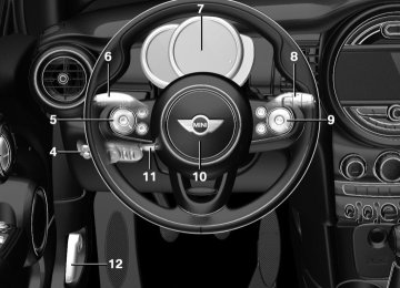
Digital compass Overview
1 Control button 2 Mirror display
Mirror display The point of the compass is displayed in the mirror when driving straight. Operating concept Various functions can be called up by pressing the control button with a pointed object, such as the tip of a ballpoint pen or similar object. The following setting options are displayed in succession, depending on how long the control button is pressed: ▷ Pressed briefly: turns display on/off. ▷ 3 to 6 seconds: compass zone setting. ▷ 6 to 9 seconds: compass calibration. ▷ 9 to 12 seconds: left/right-hand steering
setting.
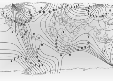
▷ 12 to 15 seconds: language setting. Setting the compass zones Sets the particular compass zones on the vehi‐ cle so that the compass operates correctly; re‐ fer to World map with compass zones.
Online Edition for Part no. 01 40 2 964 625 - X/15
147
CONTROLS
Interior equipment
World map with magnetic zones
Procedure 1. Press and hold the control button for ap‐
prox. 3 to 4 seconds. The number of the set compass zone appears in the mirror.
2. To change the zone setting, press the con‐ trol button quickly and repeatedly until the number of the compass zone that corre‐ sponds with your location appears in the mirror.
The set zone is stored automatically. The com‐ pass is ready for use again after approximately 10 seconds. Calibrating the digital compass The digital compass must be calibrated in the event of the following: ▷ The wrong compass point is displayed. ▷ The point of the compass displayed does not change despite changing the direction of travel.
▷ Not all points of the compass are displayed.
Procedure 1. Make sure that there are no large metallic objects or overhead power lines near the vehicle and that there is sufficient room to drive around in a circle.
2. Set the currently applicable compass zone. 3. Press and hold the control button for ap‐
prox. 6 to 7 seconds so that "C" appears on the display. Next, drive in a complete circle at least once at a speed of no more than 4 mph/7 km/h. If calibration is successful, the "C" is replaced by the points of the compass.
Left/right-hand steering The digital compass is already set for right or left-hand steering at the factory. Setting the language Press and hold the control button for approx. 12 to 13 seconds. Briefly press the control but‐ ton again to switch between English "E" and German "O".
148
Online Edition for Part no. 01 40 2 964 625 - X/15
Interior equipment
CONTROLS
Settings are stored automatically after approxi‐ mately 10 seconds.
Sun visor Glare shield Fold the sun visor down or up. Vanity mirror A vanity mirror is located in the sun visor be‐ hind a cover. When the cover is opened, the mirror lighting switches on.
Ashtray/cigarette lighter Overview
The ashtray is located in one of the frontal cup holders, the cigarette lighter above it in the center console.
Ashtray In order to empty the ashtray, remove the ash‐ tray from the cupholder. Lighter
WARNING Contact with hot heating elements or the
hot socket of the cigarette lighter can cause burns. Flammable materials can ignite if the
cigarette lighter falls down or is held against the respective objects. There is risk of fire and injuries. Hold the cigarette lighter on its handle. Make sure that children do not use the ciga‐ rette lighter and do not burn themselves, for example by carrying the remote control along when exiting the vehicle.◀
CAUTION If metal objects fall into the socket, they can cause a short circuit. There is risk of prop‐ erty damage. Replace the cigarette lighter or socket cover again after using the socket.◀
Push in the lighter. The lighter can be removed as soon as it pops back out.
Connecting electrical de‐ vices Information WARNING Devices and cables in the unfolding area of the airbags, for example portable navigation devices, etc., can hinder the unfolding of the airbag or be thrown around in the car's interior when unfolding. There is risk of injuries. make sure that devices and cables are not in the air‐ bag's area of unfolding.◀
CAUTION Battery chargers for the vehicle battery
can work with high voltages and currents, which means that the 12 volt on-board net‐ work can be overloaded or damaged. There is risk of property damage. Only connect battery chargers for the vehicle battery to the starting aid terminals in the engine compartment.◀
Online Edition for Part no. 01 40 2 964 625 - X/15
149
CONTROLS
Interior equipment
CAUTION If metal objects fall into the socket, they can cause a short circuit. There is risk of prop‐ erty damage. Replace the cigarette lighter or socket cover again after using the socket.◀
Sockets Sockets can be used for the running electrical devices with the engine running or with the ig‐ nition switched on. The total load of all sockets must not exceed 140 watts at 12 volts. Do not damage the socket by using non-com‐ patible connectors. In the center console
USB interface The concept Connection for USB devices with music files and for importing data, such as for Personal Profile settings. Information Observe the following when connecting: ▷ Do not use force when plugging the con‐
nector into the USB interface.
▷ Do not connect devices such as fans or
lights to the USB interface.
▷ Do not connect any USB hard drives or USB
hubs.
▷ Do not use the USB interface for recharging
external devices.
Overview
Remove the cover or cigarette lighter.
In the trunk
The socket is located on the right side in the trunk.
The USB interface is located in the front of the center console.
Cargo area Cargo cover General information When the tailgate is opened, the cargo cover is raised.
150
Online Edition for Part no. 01 40 2 964 625 - X/15
Interior equipment
CONTROLS
Information WARNING Loose objects or devices with a cable
connection to the vehicle, for example mobile phones, can be thrown into the car's interior while driving, for example in the event of an accident or during braking and evasive maneu‐ vers. There is risk of injuries. Secure loose ob‐ jects or devices with a cable connection to the vehicle in the car's interior.◀
Removing For storing bulky objects the cargo cover can be removed. 1. Detach the left and right retaining straps at
the tailgate.
2. Pull the cargo cover out of the brackets on
the left and right.
Installing 1. Slide the cargo cover forward horizontally into the two side brackets until it audibly engages.
2. Attach the left and right retaining straps at
the tailgate.
Enlarging the trunk The concept The trunk can be enlarged by folding down the rear seat backrest.
The rear backrest is divided 60–40. The back‐ rest of the left seat is connected to the backrest center section. The sides can be folded down separately or to‐ gether. Information WARNING Danger of jamming with folding down the
backrests. There is risk of injuries or risk of property damage. Make sure that the area of movement of the rear backrest is clear prior to folding down.◀ WARNING The stability of the child restraint system is limited or compromised with incorrect seat adjustment or improper installation of the child seat. There is risk of injuries or danger to life. Make sure that the child restraint system fits securely against the backrest. If possible, adjust the backrest tilt for all affected backrests and correctly adjust the seats. Make sure that seats and backrests are securely engaged. If possible, adjust the height of the head restraints or re‐ move them.◀
WARNING With an unlocked backrest, an unsecured
load can be thrown into the car's interior, for example in case of an accident, braking or eva‐ sive maneuver. There is risk of injuries. Make sure that the backrest engages into the locking after folding it back.◀
WARNING With a rear backrest that is not locked,
the protective function of the middle safety belt is not guaranteed. There is risk of injuries or danger to life. If you are using the middle safety belt, lock the wider rear backrest.◀
Online Edition for Part no. 01 40 2 964 625 - X/15
151
CONTROLS
Interior equipment
WARNING Body parts can be jammed when moving
the head restraint. There is risk of injuries. Make sure that the area of movement is clear when moving the head restraint.◀
Folding down rear seat backrests The rear seat backrest can be folded down from the front or from the trunk. Before the rear seat backrest is folded down, hook the corresponding safety belt into the belt buckle on the side.
Make sure that the child restraint system fits securely against the backrest. If possible, adjust the backrest tilt for all affected backrests and correctly adjust the seats. Make sure that seats and backrests are securely engaged. If possible, adjust the height of the head restraints or re‐ move them.◀ To transport bulky items, the trunk can be ex‐ panded by setting the backrests at a steeper angle. 1. Release the backrest, and tilt it forward. 2. Fold the frame up until it engages.
3. Fold back and engage the rear seat back‐
rest.
1. Pull the release upward to release the rear
seat backrest.
2. Fold the rear seat backrest forward. Folding back the backrest
WARNING With an unlocked backrest, an unsecured
load can be thrown into the car's interior, for example in case of an accident, braking or eva‐ sive maneuver. There is risk of injuries. Make sure that the backrest engages into the locking after folding it back.◀ Fold up the backrest and press it into the latch. Make sure that the safety belt is not pinched. Adjusting the backrest tilt
WARNING The stability of the child restraint system is limited or compromised with incorrect seat adjustment or improper installation of the child seat. There is risk of injuries or danger to life.
152
Online Edition for Part no. 01 40 2 964 625 - X/15
Storage compartments
CONTROLS
Storage compartments Vehicle features and op‐ tions This chapter describes all standard, country- specific and optional features offered with the series. It also describes features that are not necessarily available in your car, e. g., due to the selected options or country versions. This also applies to safety-related functions and sys‐ tems. The respectively applicable country provi‐ sions must be observed when using the respec‐ tive features and systems.
rest.
Information
WARNING Loose objects or devices with a cable
connection to the vehicle, for example mobile phones, can be thrown into the car's interior while driving, for example in the event of an accident or during braking and evasive maneu‐ vers. There is risk of injuries. Secure loose ob‐ jects or devices with a cable connection to the vehicle in the car's interior.◀
CAUTION Anti-slip pads such as anti-slip mats can damage the dashboard. There is risk of prop‐ erty damage. Do not use anti-slip pads.◀
Overview The following storage compartments are avail‐ able in the vehicle interior: ▷ Storage compartment in front of the cu‐
pholders.
▷ Storage tray in the center console. ▷ Glove compartment on the front passenger
side.
▷ Storage compartment in the center arm‐
▷ Compartments in the doors. ▷ Pockets on the backrests of the front seats.
Glove compartment Information WARNING Folded open, the glove compartment protrudes in the car's interior. Objects in the glove compartment can be thrown into the car's interior while driving, for example in the event of an accident or during braking and eva‐ sive maneuvers. There is risk of injuries. Always close the glove compartment immediately after using it.◀
Opening
Pull the handle. The light in the glove compartment switches on.
Closing Fold up the cover.
Online Edition for Part no. 01 40 2 964 625 - X/15
153
CONTROLS
Storage compartments
Compartments in the doors
WARNING Breakable object, for example glass bot‐ tle, can break in the event of an accident. Bro‐ ken glass can be scattered in the car's interior. There is risk of injuries. Do not stow any break‐ able objects in the car's interior.◀
Center armrest The center armrest contains a storage compart‐ ment. Opening
Cupholders Information WARNING Unsuitable containers in the cup holder and hot beverages can damage the cup holder and increase the risk of injuries in the event of an accident. There is risk of injuries or risk of property damage. Use light-weight, unbreaka‐ ble, and sealable containers. Do not transport hot beverages. Do not force objects into the cup holder.◀
Front
In the center console.
Press button, arrow 1, and open center arm rest upward, arrow 2.
Rear
Adjusting the height
For 3-door models: in front of the rear seats and in the side armrests.
Press button, arrow 1, and swing center arm rest upward or downward into the desired height, arrow 2.
154
Online Edition for Part no. 01 40 2 964 625 - X/15
Storage compartments
CONTROLS
Storage space under cargo floor panel
For 5-door models: in front of the rear seats.
Clothes hooks
WARNING Clothing articles on the clothes hooks can obstruct the view while driving. There is risk of an accident. When suspending clothing articles from the hooks, ensure that they will not ob‐ struct the driver's view.◀
WARNING Improper use of the clothes hooks can
lead to a danger of objects flying about during braking and evasive maneuvers. There is risk of injuries and risk of property damage. Only hang lightweight objects, for example clothing arti‐ cles, from the clothes hooks.◀ The clothes hooks are located above the side windows in the rear. The clothes hooks are located above the rear doors.
Located under the cargo floor panel on the right side is a trough for the onboard vehicle tool kit. To remove the onboard vehicle tool kit, fold the right side of the cargo floor panel upward.
Variable trunk floor With the variable trunk floor, the trunk can be configured corresponding to transport require‐ ments. To do this, remove the trunk floor, and insert it in the desired position. Follow instructions on securing cargo, refer to page 163. Removing the cargo floor panel
On 5-door models: To change the position of the cargo floor panel, first fold up the rear part of the cargo floor panel.
Online Edition for Part no. 01 40 2 964 625 - X/15
155
CONTROLS
Storage compartments
▷ Always secure cargo against shifting, using
straps, belts and lashing eyes, for exam‐ ple.◀
Grasp the cargo floor panel in the rear and fold slightly upward. Next, pull it backward from the supports. The cargo floor panel can be removed from the trunk above the tail lamps.
Lower position
Fold up the cargo floor panel in the lower posi‐ tion and push it behind the locks, arrow. You've reached the maximum cargo height.
Upper position
▷ Larger objects can be transported. ▷ Space for smaller objects remains between
the fixed and variable trunk floor.
Folded up position
WARNING Improper use of the variable cargo floor
panel can lead to a danger of objects flying about during braking and evasive maneuvers. There is risk of injuries and risk of property damage. ▷ Do not use the variable cargo floor panel to separate the cargo area and vehicle interior in the sense of a partition net.
▷ Only use the variable cargo floor in the
folded-up position when the backrests are folded up and locked.
▷ With the backrests folded down, a long, flat
loading surface is produced.
▷ For 3-door models:
Maximum load in this position: 330 lbs/150 kg.
▷ For 5-door models:
Maximum load in this position: 441 lbs/200 kg.
▷ Space for objects remains between the
fixed and variable trunk floor.
156
Online Edition for Part no. 01 40 2 964 625 - X/15
Storage compartments
CONTROLS
Online Edition for Part no. 01 40 2 964 625 - X/15
157
DRIVE ME.
Online Edition for Part no. 01 40 2 964 625 - X/15
AT A GLANCE
CONTROLS
DRIVING TIPS
MOBILITY
REFERENCE
Online Edition for Part no. 01 40 2 964 625 - X/15
DRIVING TIPS
Things to remember when driving
▷ For gasoline engine 4,500 rpm and
Things to remember when driving Vehicle features and op‐ tions This chapter describes all standard, country- specific and optional features offered with the series. It also describes features that are not necessarily available in your car, e. g., due to the selected options or country versions. This also applies to safety-related functions and sys‐ tems. The respectively applicable country provi‐ sions must be observed when using the respec‐ tive features and systems.
100 mph/160 km/h.
Avoid full load or kickdown under all circum‐ stances. From 1,200 miles/2,000 km The engine and vehicle speed can gradually be increased. Tires Tire traction is not optimal due to manufactur‐ ing circumstances when tires are brand-new; they achieve their full traction potential after a break-in time. Drive conservatively for the first 200 miles/300 km. Brake system Brakes require an initial break-in period of ap‐ prox. 300 miles/500 km to achieve optimal per‐ formance between brake discs and brake pads. Drive moderately during this break-in period. Clutch The function of the clutch reaches its optimal level only after a distance driven of approx. 300 miles/500 km. During this break-in period, engage the clutch gently. Following part replacement The same break-in procedures should be ob‐ served if any of the components above-men‐ tioned have to be renewed in the course of the vehicle's operating life.
Breaking-in period General information Moving parts need time to adjust to one an‐ other (break-in time). The following instructions will help accomplish a long vehicle life and good efficiency. During break-in, do not use the Launch Control, refer to page 74. Information WARNING Due to new parts and components, safety and driver assistance systems can react with a delay. There is risk of an accident. After instal‐ ling new parts or with a new vehicle, drive con‐ servatively and interfere early if necessary. Ob‐ serve the break-in procedures of the respective parts and components.◀
Engine, transmission, and axle drive Up to 1,200 miles/2,000 km Do not exceed the maximum engine and road speed:
160
Online Edition for Part no. 01 40 2 964 625 - X/15
Things to remember when driving
DRIVING TIPS
General driving notes Closing the tailgate
WARNING An open tailgate protrudes from the vehi‐ cle and can endanger occupants and other traf‐ fic participants or damage the vehicle in the event of an accident, braking or evasive ma‐ neuvers. In addition, exhaust fumes may enter the vehicle interior. There is risk of injuries or risk of property damage. Do not drive with the tailgate open.◀ If driving with the tailgate open cannot be avoided: ▷ Close all windows and the glass sunroof. ▷ Greatly increase the air flow from the vents. ▷ Drive moderately. Hot exhaust system
WARNING During driving operation, high tempera‐ tures can occur underneath the body, for ex‐ ample caused by the exhaust gas system. If combustible materials, such as leaves or grass, come in contact with hot parts of the exhaust gas system, these materials can ignite. There is risk of injuries or risk of property damage. Do not remove the heat shields installed and never apply undercoating to them. Make sure that no combustible materials can come in con‐ tact with hot vehicle parts in driving operation, idle or during parking. Do not touch the hot ex‐ haust system.◀
Mobile communication devices in the vehicle
WARNING Vehicle electronics and mobile phones can influence one another. There is radiation due to the send operations of mobile phones. There is risk of injuries or risk of property dam‐ age. If possible, in the car's interior use only
mobile phones with direct connections to an exterior antenna in order to exclude mutual disturbance and deflect the radiation from the car's interior.◀
Hydroplaning On wet or slushy roads, a wedge of water can form between the tires and road surface. This phenomenon is referred to as hydroplan‐ ing. It is characterized by a partial or complete loss of contact between the tires and the road surface, ultimately undermining your ability to steer and brake the vehicle. Driving through water
CAUTION When driving too quickly through too deep water, water can enter into the engine compartment, the electrical system or the transmission. There is risk of property damage. When driving through water, do not exceed the maximum indicated water level and the maxi‐ mum speed for driving through water.◀ When driving through water, observe the fol‐ lowing: ▷ Drive through calm water only. ▷ Drive through water only if it is not deeper
than maximum 9.8 inches/25 cm.
▷ Drive through water no faster than walking
speed, up to 3 mph/5 km/h.
Braking safely Your vehicle is equipped with ABS as a standard feature. Perform an emergency stop in situations that require such. Steering is still responsive. You can still avoid any obstacles with a minimum of steering ef‐ fort. Pulsation of the brake pedal and sounds from the hydraulic circuits indicate that ABS is in its active mode.
Online Edition for Part no. 01 40 2 964 625 - X/15
161
DRIVING TIPS
Things to remember when driving
wise the brakes may overheat and reduce brake efficiency. You can increase the engine's braking effect by shifting down, going all the way to first gear, if needed. Brake disc corrosion Corrosion on the brake discs and contamina‐ tion on the brake pads are furthered by: ▷ Low mileage. ▷ Extended periods when the vehicle is not
used at all.
▷ Infrequent use of the brakes. Corrosion will built up when the maximum pressure applied to the brake pads during brak‐ ing is not reached - thus discs don't get cleaned. Corrosion buildup on the brake discs will cause a pulsating effect on the brakes in their re‐ sponse - generally that cannot be corrected. Condensation under the parked vehicle When using the automatic climate control, con‐ densation water develops collecting under‐ neath the vehicle. Ground clearance
CAUTION If ground clearance is insufficient, there might be contact with the front or rear spoiler for example when driving over curbs or enter‐ ing into underground car parking garages. There is risk of property damage. Ensure that there is sufficient ground clearance available.◀
Objects in the area around the pedals
WARNING Objects in the driver's floor area can limit the pedal distance or block a depressed pedal. There is risk of an accident. Stow objects in the vehicle such that they are secured and cannot enter into the driver's floor area. Use floor mats that are suitable for the vehicle and can be safely attached to the floor. Do not use loose floor mats and do not layer several floor mats. Make sure that there is sufficient clearance for the pedals. Ensure that the floor mats are se‐ curely fastened again after they were removed, for example for cleaning.◀
Driving in wet conditions When roads are wet, salted, or in heavy rain, press brake pedal ever so gently every few miles. Ensure that this action does not endanger other traffic. The heat generated in this process helps dry the brake discs and pads. In this way braking efficiency will be available when you need it. Hills
WARNING Light but consistent brake pressure can lead to high temperatures, brakes wearing out and possibly even brake failure. There is risk of an accident. Avoid placing excessive stress on the brake system.◀
WARNING In idle or with the engine switched off, safety-relevant functions are restricted or not available anymore, for example braking effect of the engine or braking force and steering support. There is risk of an accident. Do not drive in idle or with the engine switched off.◀ Drive long or steep downhill gradients in the gear that requires least braking efforts. Other‐
162
Online Edition for Part no. 01 40 2 964 625 - X/15
Loading Vehicle features and op‐ tions This chapter describes all standard, country- specific and optional features offered with the series. It also describes features that are not necessarily available in your car, e. g., due to the selected options or country versions. This also applies to safety-related functions and sys‐ tems. The respectively applicable country provi‐ sions must be observed when using the respec‐ tive features and systems.
Information
WARNING High gross weight can overheat the tires, damage them, and cause a sudden drop in tire inflation pressure. There is risk of an accident. Pay attention to the permitted load capacity of the tires and never exceed the permitted gross weight.◀
WARNING Loose objects or devices with a cable
connection to the vehicle, for example mobile phones, can be thrown into the car's interior while driving, for example in the event of an accident or during braking and evasive maneu‐ vers. There is risk of injuries. Secure loose ob‐ jects or devices with a cable connection to the vehicle in the car's interior.◀
CAUTION Fluids in the cargo area can cause dam‐ age. There is risk of property damage. Make sure that no fluids leak in the cargo area.◀
Loading
DRIVING TIPS
Determining the load limit 1. Locate the following statement on your ve‐
hicle’s placard: ▷ The combined weight of occupants and
cargo should never exceed XXX kg or YYY lbs. Otherwise, damage to the ve‐ hicle and unstable driving situations may result.
2. Determine the combined weight of the
driver and passengers that will be riding in your vehicle.
3. Subtract the combined weight of the driver and passengers from XXX kilograms or YYY pounds.
4. The resulting figure equals the available amount of cargo and luggage load ca‐ pacity. For example, if the YYY amount equals 1,000 lbs and there will be four 150 lbs pas‐ sengers in your vehicle, the amount of available cargo and luggage load capacity is 400 lbs: 1,000 lbs minus 600 lbs = 400 lbs.
5. Determine the combined weight of luggage
and cargo being loaded on the vehicle. That weight may not safely exceed the available cargo and luggage load capacity calculated in Step 4.
Online Edition for Part no. 01 40 2 964 625 - X/15
163
DRIVING TIPS
Loading
Load On 3-door models
On 5-door models
Securing cargo Information WARNING Improperly stowed objects can shift and be thrown into the car's interior, for example in the event of an accident or during braking and evasive maneuvers. Vehicle occupants can be hit and injured. There is risk of injuries. Stow and secure objects and cargo properly.◀ ▷ Small and light cargo: secure with retaining
straps or draw straps.
▷ Larger and heavy cargo: secure with cargo
straps.
Attach the cargo straps, retaining straps or draw straps to the lashing eyes in the cargo area. Lashing eyes in the cargo area
The maximum load is the sum of the weight of the occupants and the cargo. The greater the weight of the occupants, the less cargo that can be transported.
Stowing cargo ▷ Cover sharp edges and corners on the
cargo.
▷ Heavy cargo: stow as far forward as possi‐ ble, directly behind and at the bottom of the rear passenger seat backrests.
▷ Very heavy cargo: when the rear seat is not
occupied, secure each of the outer safety belts in the opposite buckle.
▷ If necessary, fold down the rear backrests
to stow cargo.
▷ Do not stack cargo above the top edge of
the backrests.
Without storage compartment package: to se‐ cure the cargo there are two lashing eyes, ar‐ row 1, in the cargo area. With storage compartment package: to secure the cargo there are six lashing eyes, arrows 1
and 2, in the cargo area.Roof-mounted luggage rack Information Installation only possible with roof rack.
164
Online Edition for Part no. 01 40 2 964 625 - X/15
Roof racks are available as special accessories. Securing Follow the installation instructions of the roof rack. Loading Because roof racks raise the vehicle's center of gravity when loaded, they have a major effect on vehicle handling and steering response. Therefore, note the following when loading and driving: ▷ Do not exceed the approved roof/axle loads and the approved gross vehicle weight.
▷ Be sure that adequate clearance is main‐
tained for tilting and opening the glass sun‐ roof.
▷ Distribute the roof load uniformly. ▷ The roof load should not extend past the
loading area.
▷ Always place the heaviest pieces on the
bottom.
▷ Secure the roof luggage firmly, e.g., tie with
ratchet straps.
▷ Do not let objects project into the opening
path of the tailgate.
▷ Drive cautiously and avoid sudden acceler‐ ation and braking maneuvers. Take corners gently.
Rear luggage rack General information Installation only possible with rear luggage rack preparation. Rear racks are available as special accessories. Information Follow the installation instructions of the rear luggage rack.
Loading
DRIVING TIPS
Drive cautiously and avoid sudden acceleration and braking maneuvers. Take corners gently. Securing COOPER
COOPER S
The anchorage points, arrow 1, and the socket, arrow 2, are located below the covers in the bumper. Remove the covers before installing the rear luggage rack. Power consumption Before starting to drive, check the function of the rear luggage rack lights. The rear luggage rack lights must not consume more than: ▷ Turn signals: 42 watts per side. ▷ Rear lights: 50 watts per side. ▷ Brake lights: 84 watts in total. ▷ Rear fog lights: 42 watts in total. ▷ Backup lamp: 42 watts in total.
Online Edition for Part no. 01 40 2 964 625 - X/15
165
DRIVING TIPS
Saving fuel
Saving fuel Vehicle features and op‐ tions This chapter describes all standard, country- specific and optional features offered with the series. It also describes features that are not necessarily available in your car, e. g., due to the selected options or country versions. This also applies to safety-related functions and sys‐ tems. The respectively applicable country provi‐ sions must be observed when using the respec‐ tive features and systems.
General information Your vehicle contains advanced technology for the reduction of fuel consumption and emis‐ sions. Fuel consumption depends on a number of dif‐ ferent factors. The implementation of certain measures, driv‐ ing style and regular maintenance can influ‐ ence fuel consumption and environmental im‐ pact.
Remove unnecessary cargo Additional weight increases fuel consumption.
Remove attached parts following use Remove roof-mounted or rear luggage racks which are no longer required following use. Attached parts on the vehicle impair the aero‐ dynamics and increase the fuel consumption.
Close the windows and glass sunroof Driving with the glass sunroof and windows open results in increased air resistance and raises fuel consumption.
Tires General information Tires can affect fuel consumption in various ways, for example, tire size may influence fuel consumption. Check the tire inflation pressure regularly Check and, if needed, correct the tire inflation pressure at least twice a month and before starting on a long trip. Low tire inflation pressure increases rolling re‐ sistance and thus raises fuel consumption and tire wear.
Drive away without de‐ lay Do not wait for the engine to warm-up while the vehicle remains stationary. Start driving right away, but at moderate engine speeds. This is the fastest way for the cold engine to reach its operating temperature.
Look well ahead when driving Avoid unnecessary acceleration and braking.
166
Online Edition for Part no. 01 40 2 964 625 - X/15
By maintaining a suitable distance to the vehi‐ cle driving ahead of you. Driving smoothly and proactively reduces fuel consumption.
Avoid high engine speeds As a rule: driving at low engine speeds lowers fuel consumption and reduces wear. Use 1st gear to get the vehicle moving. Starting with the 2nd gear, accelerate rapidly. When ac‐ celerating, shift up before reaching high engine speeds. When you reach the desired speed, shift into the highest applicable gear and drive with the engine speed as low as possible and at a con‐ stant speed. The gear shift indicator, refer to page 83, of your vehicle indicates the most fuel efficient gear.
Use coasting conditions When approaching a red light, take your foot off the accelerator and let the vehicle coast to a halt. For going downhill take your foot off the accel‐ erator and let the vehicle roll. The flow of fuel is interrupted while coasting.
Switch off the engine during longer stops Switch off the engine during longer stops, for example, at traffic lights, railroad crossings or in traffic congestion. Auto Start/Stop function The Auto Start/Stop function of your vehicle au‐ tomatically switches off the engine during a stop.
Saving fuel
DRIVING TIPS
If the engine is switched off and then restarted rather than leaving the engine running con‐ stantly, fuel consumption and emissions are re‐ duced. Savings can begin within a few seconds of switching off the engine. In addition, fuel consumption is also deter‐ mined by other factors, such as driving style, road conditions, maintenance or environmental factors.
Switch off any functions that are not currently needed Functions such as seat heating and the rear window defroster require a lot of energy and consume additional fuel, especially in city and stop-and-go traffic. Therefore, switch off these functions if they are not actually needed.
Have maintenance car‐ ried out Have vehicles maintained regularly to achieve optimal vehicle efficiency and service life. MINI recommends that maintenance work be per‐ formed by a MINI service center. Also note the MINI maintenance systems, refer to page 202.
GREEN Mode The concept The GREEN Mode supports a driving style that saves on fuel consumption. For this purpose, the engine control and comfort features, e. g. the climate control output, are adjusted. For Steptronic transmission:
Online Edition for Part no. 01 40 2 964 625 - X/15
167
DRIVING TIPS
Saving fuel
The Coasting driving condition is enabled under certain conditions. Under certain conditions the engine is auto‐ matically decoupled from the transmission in selector lever position D. The vehicle continues traveling with the engine idling to reduce fuel consumption. Selector lever position D remains engaged. An indicator provides information about the distance traveled in Coasting mode. In addition, context-sensitive instructions are displayed to assist with an optimized fuel con‐ sumption driving style. The achieved extended range is displayed in the instrument cluster. Overview The system includes the following MINIMAL functions and displays: ▷ GREEN bonus range, refer to page 169. ▷ GREEN tips driving instruction, refer to
page 169.
▷ GREEN climate control, refer to page 168. ▷ MINIMALISM analyzer, refer to page 171. ▷ Coasting driving condition, refer to
page 170.
Activating GREEN Mode
Turn Driving Dynamics Control to the right until GREEN Mode is displayed in the instrument clus‐ ter.
Configuring GREEN Mode Via the Driving Dynamics Control 1. Activating GREEN Mode. 2. "Configure GREEN" 3. Configure the program. Via onboard monitor: 1.
"Settings"
"Settings"
2. "GREEN Mode" Or 1. 2. "Driving mode" 3. "Configure GREEN" Configure the program. GREEN tip ▷ "Tip at:"