- 2010 Mercedes-Benz R Class Owners Manuals
- Mercedes-Benz R Class Owners Manuals
- 2006 Mercedes-Benz R Class Owners Manuals
- Mercedes-Benz R Class Owners Manuals
- 2008 Mercedes-Benz R Class Owners Manuals
- Mercedes-Benz R Class Owners Manuals
- 2009 Mercedes-Benz R Class Owners Manuals
- Mercedes-Benz R Class Owners Manuals
- 2007 Mercedes-Benz R Class Owners Manuals
- Mercedes-Benz R Class Owners Manuals
- 2011 Mercedes-Benz R Class Owners Manuals
- Mercedes-Benz R Class Owners Manuals
- Download PDF Manual
-
pears in the multifunction display.
As an alternative, you may unlock the vehi- cle via Internet using the ID and password sent to you shortly after the completion of your acquaintance call.
The Response Center will then unlock your vehicle with the remote door unlocking feature.
The remote door unlock feature is available if the relevant cellular phone network is available. The SOS button will flash and the message Connecting call will appear in the multifunction display to indicate receipt of the door unlock command. Once the vehicle is unlocked, a Response Center specialist may attempt to establish voice contact with the vehicle occupants. If the tailgate recessed handle was pulled for more than 20 seconds before door unlock authorization was received by the Response Center, you must wait 15 minutes before pulling the tailgate recessed handle again.
Controls in detail Useful features
Stolen Vehicle Recovery services In the event your vehicle was stolen: 왘 Report the incident to the police. The police will issue a numbered incident report.
왘 Pass this number on to the
Mercedes-Benz Response Center along with your password issued to you when you subscribed to the service. The Response Center will then attempt to covertly contact the vehicle’s Tele Aid system. Once the vehicle is located, the Response Center will contact the local law enforcement and you. The vehicle’s location will only be provided to law enforcement.
319
Controls in detail Useful features
When the anti-theft alarm or the tow-away alarm stays on for more than 30 seconds, a call is initiated automat- ically to the Response Center. See anti-theft alarm system (컄 page 104) and tow-away alarm (컄 page 106).
Garage door opener*
The integrated remote control is capable of operating up to three separately controlled devices. It provides a convenient way to replace up to three hand-held remote controls used to operate devices such as garage door openers, gate openers, or other devices compatible with HomeLink® or some other systems. Before the integrated remote control can be used, it must be programmed to the garage door opener, gate operator or other device you wish to operate. See the follow- ing instructions for programming informa- tion.
320
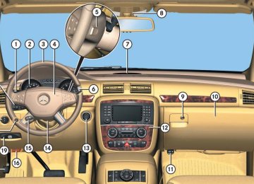
Indicator lamp
Interior rear view mirror with integrated remote control 2 3 4 Signal transmitter button Needed for programming (not part of vehi- cle equipment):
Hand-held remote control of ga- rage door opener, gate operator or other device Hand-held remote control but- ton
Warning!
When programming a garage door opener, it is advised to park outside the garage.
Do not run the engine while programming the integrated remote control. Inhalation of exhaust gas is hazardous to your health. All exhaust gas contains carbon monoxide, and inhaling it can cause unconsciousness and possible death.
Programming the integrated remote control Step 1: 왘 Switch on the ignition (컄 page 38).
Before programming the integrated remote control to a garage door opener or gate operator, make sure people and objects are out of the way of the device to prevent po- tential harm or damage. When programming a garage door opener, the door moves up or down. When programming a gate operator, the gate opens or closes.
Do not use the integrated remote control with any garage door opener that lacks safety stop and reverse features as required by U.S. federal safety standards (this includes any garage door opener model manufactured before April 1, 1982). A garage door that cannot detect an object – signaling the door to stop and reverse – does not meet current U.S. federal safety standards.
Controls in detail Useful features
Step 2: 왘 If you have previously programmed an signal transmitter button and wish to retain its programming, proceed to step 3. If you are programming the integrated remote control for the first time, press and hold the two outer signal transmit- ter buttons 2 and 4 and release them only when the indicator lamp 1 begins to flash after approximately 20 seconds (do not hold the button for longer than 30 seconds). This proce- dure erases any previous settings for all three channels and initializes the memory. If you later wish to program a second and/or third hand-held transmitter to the remaining two signal transmitter buttons, do not repeat this step and be- gin directly with step 3.
컄컄
321
Controls in detail Useful features
컄컄
Step 3: 왘 Hold the end of the hand-held remote
control 5 of the device you wish to train approximately 2 to 5 in (5 to12 cm) away from the signal trans- mitter button (2, 3 or 4) to be pro- grammed, while keeping the indicator lamp 1 in view.
Step 4: 왘 Using both hands, simultaneously
press the hand-held remote control button 6 and the desired signal trans- mitter button (2, 3 or 4). Do not release the buttons until step 5 is com- pleted. The indicator lamp 1 will flash, first slowly and then rapidly.
322
The indicator lamp 1 flashes immedi- ately the first time the signal transmit- ter button is programmed. If this button has already been programmed, the in- dicator lamp will only start flashing af- ter 20 seconds.
Step 5: 왘 After the indicator lamp 1 changes from a slow to a rapidly flashing light, release the hand-held remote control button and the signal transmitter but- ton. Step 6: 왘 Press and hold the just-trained signal transmitter button (2, 3 or 4) and observe the indicator lamp 1.
If the indicator lamp 1 stays on constantly, programming is complete and your device should activate when the respective signal transmitter button (2, 3 or 4) is pressed and re- leased.
If the indicator lamp 1 flashes rapidly for about 2 seconds and then turns to a constant light, continue with programming steps 8 through 12 as your garage door opener may be equipped with the “rolling code” feature.
Step 7: 왘 To program the remaining two signal transmitter buttons, repeat the steps above starting with step 3.
Controls in detail Useful features
Rolling code programming To train a garage door opener (or other rolling code devices) with the rolling code feature, follow these instructions after completing the “Programming” portion (steps 1 through 6) of this text. (A second person may make the following training procedures quicker and easier.) Step 8: 왘 Locate “training” button on the garage
door opener motor head unit. Exact location and color of the button may vary by garage door opener brand. Depending on manufacturer, the “training” button may also be referred to as “learn”or “smart” button. If there is difficulty locating the transmitting button, refer to the garage door opener operator’s manual.
Step 9: 왘 Press the “training” button on the ga-
rage door opener motor head unit. The “training light” is activated.
You have 30 seconds to initiate the follow- ing two steps. Step 10: 왘 Return to the vehicle and firmly press, hold for 2 seconds and release the pro- grammed signal transmitter button (2, 3 or 4).
Step 11: 왘 Press, hold for 2 seconds and release same signal transmitter button a sec- ond time to complete the training pro- cess.
Some garage door openers (or other rolling code equipped devices) may require you to press, hold for 2 seconds and release the same signal transmit- ter button a third time to complete the training process.
Step 12: 왘 Confirm the garage door operation by pressing the programmed signal trans- mitter button (2, 3 or 4).
Step 13: 왘 To program the remaining two signal transmitter buttons, repeat the steps above starting with step 3.
323
왘 While still holding down the signal transmitter button (2, 3 or 4), “cycle” your hand-held remote control button 6 as follows: Press and hold button 6 for 2 seconds, then release it for 2 seconds, and again press and hold it for 2 seconds. Repeat this se- quence on the hand-held remote con- trol until the frequency signal has been learned. Upon successful training, the indicator lamp 1 will flash slowly and then rapidly after several seconds.
왘 Proceed with programming step 5 and
step 6 to complete.
Upon completion of programming the integrated remote control, make sure you retain the hand-held remote con- trol that came with the garage door opener, gate operator or other device. You may need it for use in other vehi- cles, for future programming of an integrated remote control, or simply for continued use as a hand-held remote control to operate the respective device in other situations.
Controls in detail Useful features
Gate operator/Canadian programming Canadian radio-frequency laws require transmitter signals to “time-out” (or quit) after several seconds of transmission which may not be long enough for the integrated signal transmitter to pick up the signal during programming. Similar to this Canadian law, some U.S. gate operators are designed to “time-out” in the same manner. If you live in Canada or if you are having difficulties programming a gate operator (regardless of where you live) by using the programming procedures, replace step 4 with the following: Step 4: 왘 Press and hold the signal transmitter button (2, 3 or 4). Do not release this button until it has been successful- ly trained.
324
Reprogramming a single signal trans- mitter button To program a device using a signal trans- mitter button previously trained, follow these steps: 왘 Switch on the ignition (컄 page 38). 왘 Press and hold the desired signal transmitter button (2, 3 or 4). Do not release the button.
왘 The indicator lamp 1 will begin to
flash after 20 seconds. Without releas- ing the signal transmitter button, pro- ceed with programming starting with step 3.
Operation of integrated remote control 왘 Switch on the ignition (컄 page 38). 왘 Select and press the appropriate inte- grated signal transmitter button (2, 3 or 4) to activate the remote con- trolled device. The integrated remote control trans- mitter continues to send the signal as long as the button is pressed – up to 20 seconds.
Controls in detail Useful features
Erasing the integrated remote control memory 왘 Switch on the ignition (컄 page 38). 왘 Simultaneously press and hold down
the outer signal transmitter buttons 2 and 4, for approximately 20 seconds, until the indicator lamp 1 flashes rap- idly. Do not hold for longer than 30 seconds. The codes of all three channels are erased.
If you sell your vehicle, erase the codes of all three channels.
325
Controls in detail Useful features
Programming tips If you are having difficulty programming the integrated remote control, here are some helpful tips: 앫 Check the frequency of the hand-held remote control 5 (typically located on the reverse side of the remote). The in- tegrated remote control is compatible with radio-frequency devices operating between 288-399 MHz.
앫 Put a new battery in the hand-held re- mote control 5. This will increase the likelihood of the hand-held remote con- trol sending a faster and more accurate signal to the integrated remote control.
앫 While performing step 3, hold the
hand-held remote control 5 at differ- ent lengths and angles from the signal transmitter button (2, 3 or 4) you are programming. Attempt varying an- gles at the distance of 2 to 5 inches (5 to 12 cm) away or the same angle at varying distances.
앫 If another hand-held remote control is available for the same device, try the programming steps again using that other hand-held remote control. Make sure new batteries are in the hand-held remote control before beginning the procedure.
앫 Straighten the antenna wire from the
garage door opener assembly. This may help improve transmitting and/or receiving signals.
Certain types of garage door openers are incompatible with the integrated remote control. If you should experi- ence further difficulties with program- ming the integrated remote control, contact an authorized Mercedes-Benz Light Truck Center, or call Mercedes-Benz Customer Assistance Center (in the USA only) at 1-800-FOR-MERCedes, or Customer Service (in Canada) at 1-800-387-0100.
326
USA only: This device complies with Part 15 of the FCC Rules. Operation is subject to the following two conditions: (1) This device may not cause harmful
interference, and
(2) this device must accept any
interference received, including interference that may cause undesired operation.
Any unauthorized modification to this device could void the user’s authority to operate the equipment.
Compass
Calling up the compass 왘 Press button è or ÿ repeatedly
until the AIRMATIC/Compass menu appears in the multifunction display. The compass displays the direction into which the vehicle is currently trav- eling: N, NE, E, SE, S, SW, W or NW.
Canada only: This device complies with RSS-210 of Industry Canada. Operation is subject to the following two conditions: (1) This device may not cause interfer-
ence, and
(2) this device must accept any inter-
ference received, including interfer- ence that may cause undesired operation of the device.
Any unauthorized modification to this device could void the user’s authority to operate the equipment.
Example for compass display on vehicles equipped with AIRMATIC*
If your vehicle is not equipped with AIRMATIC*, the multifunction display will show the compass only.
Controls in detail Useful features
The presence of buildings, bridges, power lines and large antenna masts can influence the displayed values. Metallic or magnetic objects in or on the vehicle can influence the accuracy of the compass.
To make sure the display is correct, the compass must be set to the proper geo- graphic zone (컄 page 186). It may also be necessary to calibrate the compass (컄 page 187).
If the compass is not calibrated or its function is impaired by outside influ- ences, the message Compass - - - appears in the multifunction display.
327
Controls in detail Useful features
Floormats*
Warning!
Whenever you are using floormats, make sure there is enough clearance and that the floormats are securely fastened.
Floormats should always be securely fas- tened using eyelets 2 and retainer pins 1. Before driving off, check that the floormats are securely in place and adjust them if nec- essary. A loose floormat could slip and hinder proper function of the pedals.
To install or remove the floormats more easily, move the driver’s seat or front passenger seat as far to the rear as possible (컄 page 43).
328
Infrared reflecting windshield*
1 Retainer pin 2 Eyelet
Removing 왘 Pull floormat off of retainer pins 1. 왘 Remove the floormat.
Installing 왘 Lay down the floormat in the respective
footwell.
왘 Press floormat eyelets 2 onto retainer
pins 1.
1 Infrared transparent areas Your vehicle is equipped with infrared re- flecting glass, which reduces the amount of radiated heat entering the vehicle interi- or through the windows. The infrared reflecting glass also prevents the transmission of signals through the glass by in-vehicle electronic devices (e.g. electronic toll collection devices). To allow the use of these devices in the ve- hicle, infrared transparent areas are placed in the windshield.
Operation The first 1000 miles (1500 km)
Driving instructions
At the gas station
Engine compartment
Tires and wheels
Winter driving
Maintenance
Vehicle care
329
Operation The first 1000 miles (1500 km)
In the “Operation” section you will find detailed information on operating, main- taining and caring for your vehicle.
330
After 1000 miles (1500 km) you may gradually increase vehicle and engine speeds to the permissible maximum. All of the above instructions, as may apply to your vehicle type, also apply when the first 1000 miles (1500 km) after the en- gine, the transfer case, the front differen- tial or the rear differential has been replaced.
Always obey applicable speed limits.
The more cautiously you treat your vehicle during the break-in period, the more satis- fied you will be with its performance later on. 앫 Drive your vehicle during the first
1000 miles (1500 km) at varying but moderate vehicle and engine speeds. 앫 During this period, avoid heavy loads
(full throttle driving) and excessive engine speeds (no more than 2/3 of maximum rpm in each gear).
앫 Shift gears in a timely manner. 앫 Avoid accelerating by kick-down. 앫 Do not attempt to slow the vehicle
down by shifting to a lower gear using the gear selector lever.
앫 Select gear ranges 3, 2 or 1
(컄 page 202) only when driving at moderate speeds (for hill driving).
앫 Select C as the preferred shift program (컄 page 204) for the first 1000 miles (1500 km).
Operation Driving instructions
Fuel consumption is also increased by driving in cold weather, in stop-and-go traffic, on short trips and in hilly area.
Pedals
Warning!
Drinking and driving
Warning!
Keep driver’s foot area clear at all times. Ob- jects stored in this area may impair pedal movement.
Drinking and driving and/or taking drugs and driving are a very dangerous combina- tion. Even a small amount of alcohol or drugs can affect your reflexes, perceptions and judgment.
The possibility of a serious or even fatal accident are greatly increased when you drink or take drugs and drive.
Do not drink or take drugs and drive or allow anyone to drive who has been drinking or taking drugs.
Power assistance
Warning!
With the engine not running, there is no power assistance for the brake and steering systems. In this case, it is important to keep in mind that a considerably higher degree of effort is necessary to brake and steer the ve- hicle.
왔 Driving instructions Drive sensibly – save fuel
Fuel consumption, to a great extent, depends on driving habits and operating conditions. To save fuel you should: 앫 Keep tires at the recommended infla-
tion pressures.
앫 Remove unnecessary loads. 앫 Remove roof rack when not in use. 앫 Allow engine to warm up under low
load use.
앫 Avoid frequent acceleration and decel-
eration.
앫 Have all maintenance work performed at the intervals specified in the Mainte- nance Booklet and as required by the Maintenance System (U.S. vehicles) or FSS PLUS (Canada vehicles). Contact an authorized Mercedes-Benz Light Truck Center.
331
Operation Driving instructions
Brakes
Warning!
After driving in heavy rain for some time without applying the brakes or through wa- ter deep enough to wet brake components, the first braking action may be somewhat reduced and increased pedal pressure may be necessary to obtain expected braking ef- fect. Maintain a safe distance from vehicles in front.
Resting your foot on the brake pedal will cause excessive and premature wear of the brake pads.
It can also result in the brakes overheating, thereby significantly reducing their effec- tiveness. It may not be possible to stop the vehicle in sufficient time to avoid an acci- dent.
332
To help prevent brake disk corrosion after driving on wet road surfaces (particularly salted roads), it is advisable to brake the vehicle with considerable force prior to parking. The heat generated serves to dry the brakes. If your brake system is normally only sub- jected to moderate loads, you should occa- sionally test the effectiveness of the brakes by applying above-normal braking pressure at higher speeds. This will also enhance the grip of the brake pads.
Warning!
Make sure not to endanger any other road users when carrying out these braking maneuvers.
If the parking brake is released and the brake warning lamp in the instrument clus- ter stays on and there is no audible warn- ing (EBP), the brake fluid level in the reservoir is too low. Brake pad wear or a leak in the system may be the reason for low brake fluid in the reservoir. Have the brake system inspected immedi- ately. Contact an authorized Mercedes-Benz Light Truck Center. All checks and service work on the brake system should be carried out by qualified technicians only. Contact an authorized Mercedes-Benz Light Truck Center. Only install brake pads and brake fluid recommended by Mercedes-Benz.
Refer to the description of the Brake Assist System (BAS) (컄 page 99).
Warning!
If other than recommended brake pads are installed, or other than recommended brake fluid is used, the braking properties of the vehicle can be degraded to an extent that safe braking is substantially impaired. This could result in an accident.
When driving down long and steep grades, relieve the load on the brakes by shifting into a lower gear to use the engine’s braking power. This helps prevent overheating of the brakes and reduces brake pad wear. When using the engine’s braking pow- er, a drive wheel may not spin for an ex- tended period of time, e.g. on slippery road surfaces. This may cause serious damage to the drivetrain which is not covered by the Mercedes-Benz Limited Warranty.
After hard braking, it is advisable to drive on for some time, rather than immediately park, so that the air stream will cool down the brakes faster.
Operation Driving instructions
Driving off
Apply the brakes to test them briefly after driving off. Perform this procedure only when the road is clear of other traffic. Warm up the engine smoothly. Do not place full load on the engine until the oper- ating temperature has been reached. When starting off on a slippery surface, do not allow a drive wheel to spin for an extended period with the ESP® switched off. Doing so may cause serious damage to the drivetrain which is not covered by the Mercedes-Benz Limited Warranty.
Simultaneously depressing the accelerator pedal and applying the brake reduces engine performance and causes premature brake and drivetrain wear.
333
Operation Driving instructions
Parking
Set the parking brake whenever park- ing or leaving the vehicle. In addition, set the automatic transmission to position P. When parking on hills, always turn front wheels towards the curb.
Warning!
To reduce the risk of personal injury, or damage to the vehicle powertrain, as a result of vehicle movement, before turning off the engine and leaving the vehicle al- ways: 앫 Keep right foot on brake pedal. 앫 Firmly depress parking brake pedal. 앫 Set the automatic transmission to
position P.
334
앫 When parked on an incline, turn front
wheel towards the road curb.
앫 Turn the SmartKey to starter switch
position 0 and remove, or press KEYLESS-GO* start/stop button (vehi- cles with KEYLESS-GO*).
앫 Take the SmartKey or the SmartKey with KEYLESS-GO* with you and lock vehicle when leaving.
Tires
Warning!
If you feel a sudden significant vibration or ride disturbance, or you suspect that possi- ble damage to your vehicle has occurred, you should turn on the hazard warning flash- ers, carefully slow down, and drive with cau- tion to an area which is a safe distance from the road.
Inspect the tires and the vehicle underbody for possible damage. If the vehicle or tires appear unsafe, have the vehicle towed to the nearest Mercedes-Benz Light Truck Center or tire dealer for repairs.
Treadwear indicators (TWI) are required by law. These indicators are located in six places on the tread circumference and become visible at a tread depth of approximately 1/16 in (1.6 mm), at which point the tire is considered worn and should be replaced.
The treadwear indicator appears as a solid band across the tread.
Warning!
Warning!
Although the applicable federal motor vehicle safety laws consider a tire to be worn when the treadwear indicators (TWI) become visible at approximately 1/16 in (1.6 mm), we recommend that you do not allow your tires to wear down to that level. As tread depth approaches 1/8 in (3 mm), the adhesion properties on a wet road are sharply reduced.
Depending upon the weather and/or road surface (conditions), the tire traction varies widely.
Do not drive with a flat tire. A flat tire affects the ability to steer or brake the vehicle. You may lose control of the vehicle. Continued driving with a flat tire or driving at high speed with a flat tire will cause excessive heat build-up and possibly a fire.
Hydroplaning
Depending on the depth of the water layer on the road, hydroplaning may occur, even at low speeds and with new tires. Reduce vehicle speed, avoid track grooves in the road and apply brakes cautiously in the rain.
Specified tire pressures must be main- tained. This applies particularly if the tires are subjected to high loads (e.g. high speeds, heavy loads, high ambient temper- atures).
Operation Driving instructions
Tire traction
The safe speed on a wet, snow covered or icy road is always lower than on a dry road. You should pay particular attention to the condition of the road whenever the outside temperatures are close to the freezing point.
Warning!
If ice has formed on the road, tire traction will be substantially reduced. Under such weather conditions, drive, steer and brake with extreme caution.
335
Operation Driving instructions
Mercedes-Benz recommends winter tires (컄 page 390) with a minimum tread depth of approximately 1/6 in (4 mm) on all four wheels for the winter season to ensure normal balanced handling characteristics. On packed snow, they can reduce your stopping distance compared to summer tires. Stopping distance, however, is still consid- erably greater than when the road is not covered with snow or ice. Exercise appro- priate caution.
Avoid spinning of one drive wheel. This may cause serious damage to the drivetrain which is not covered by the Mercedes-Benz Limited Warranty.
Tire speed rating
Regardless of the tire speed rating, local speed limits should be obeyed. Use prudent driving speeds appropriate to pre- vailing conditions.
Warning!
Even when permitted by law, never operate a vehicle at speeds greater than the maxi- mum speed rating of the tires.
Exceeding the maximum speed for which tires are rated can lead to sudden tire failure, causing loss of vehicle control and possibly resulting in an accident and/or serious injury and possible death, for you and for others.
336
R 350, R 500
Your vehicle is factory equipped with “H”-rated tires, which have a speed rating of 130 mph (210 km/h). An electronic speed limiter prevents your vehicle from exceeding a speed of 130 mph (210 km/h).R 350, R 500 (with Sport Package*) Your vehicle is factory equipped with “W”-rated tires, which have a speed rating of 168 mph (270 km/h). An electronic speed limiter prevents your vehicle from exceeding a speed of 130 mph (210 km/h).
For information on speed ratings for winter tires, see “Winter tires” (컄 page 390). For additional general information on tire speed markings on the tire side- wall, see “Tire speed rating” (컄 page 388).
Operation Driving instructions
Winter driving instructions
The most important rule for slippery or icy roads is to drive sensibly and to avoid abrupt acceleration, braking and steering maneuvers. Do not use the cruise control system under such conditions. When the vehicle is in danger of skidding, move gear selector lever to position N. Try to keep the vehicle under control by corrective steering action.
For information on driving with snow chains, see “Snow chains” (컄 page 391).
Road salts and chemicals can adversely af- fect braking efficiency. Increased pedal force may become necessary to produce the normal brake effect. Depressing the brake pedal periodically when traveling at length on salt-strewn roads can bring road-salt-impaired braking efficiency back to normal. If the vehicle is parked after being driven on salt-treated roads, the braking efficien- cy should be tested as soon as possible af- ter driving is resumed.
Warning!
If the vehicle becomes stuck in snow, make sure that snow is kept clear of the exhaust pipe and from around the vehicle with the engine running. Otherwise, deadly carbon monoxide (CO) gases may enter vehicle in- terior resulting in unconsciousness and death.
To assure sufficient fresh air ventilation, open a window slightly on the side of the ve- hicle not facing the wind.
Warning!
Warning!
Warning!
Make sure not to endanger any other road users when carrying out these braking maneuvers.
On slippery road surfaces, never downshift in order to obtain braking action. This could result in drive wheel slip and reduced vehi- cle control. Your vehicle’s ABS will not pre- vent this type of control loss.
The outside temperature indicator is not de- signed to serve as an ice-warning device and is therefore unsuitable for that purpose. In- dicated temperatures just above the freez- ing point do not guarantee that the road surface is free of ice.
For more information, see “Winter driving” (컄 page 390).
337
Operation Driving instructions
Standing water
To prevent water from entering the pas- senger compartment or the engine com- partment if you must drive through standing water, keep in mind that 앫 the maximum depth of the water may
not exceed 10 in (25 cm)
앫 you must drive slowly
Vehicles with AIRMATIC*: If you have selected the raised level (컄 page 272) before driving through standing water, the maximum water depth is 12 in (30 cm).
338
Do not drive through flooded areas or water of unknown depth. Before driving through water, determine its depth. Never accelerate before driving into water. The bow wave could force water into the engine and auxiliary equip- ment, thus damaging them. If you must drive through standing wa- ter, drive slowly to prevent water from entering the passenger compartment or the engine compartment. Water in these areas could cause damage to electrical components or wiring of the engine or transmission, or could result in water being ingested by the engine through the air intake, causing severe internal engine damage. Any such dam- age is not covered by the Mercedes-Benz Limited Warranty.
Passenger compartment
Warning!
Always fasten items being carried as secure- ly as possible.
In an accident, during hard braking or sud- den maneuvers, loose items will be thrown around inside the vehicle, and cause injury to vehicle occupants unless the items are securely fastened in the vehicle.
The rear cargo compartment is the preferred place to carry objects. Always use the parti- tion net when transporting cargo. Partition net cannot secure hard or heavy objects. Al- ways fasten items being carried as securely as possible using the cargo tie-down rings in the cargo floor area and fastening materials.
Driving abroad
Abroad, there is an extensive Mercedes-Benz service network at your disposal. If you plan to drive into areas which are not listed in the index of your Mercedes-Benz Light Truck Center directo- ry, you should request pertinent informa- tion from an authorized Mercedes-Benz Light Truck Center.
Operation Driving instructions
Control and operation of radio transmitters
Telephones and two-way radios
Modular COMAND System, radio and telephone*
Warning!
Do not forget that your primary responsibili- ty is to drive the vehicle. Only operate the Modular COMAND System, radio or tele- phone1 if road, weather and traffic condi- tions permit.
Bear in mind that at a speed of just 30 mph (approximately 50 km/h), your vehicle is covering a distance of 44 feet (approximate- ly 14 m) every second.
1 Observe all legal requirements.
Warning!
Never operate radio transmitters equipped with a built-in or attached antenna (i.e. with- out being connected to an external antenna) from inside the vehicle while the engine is running. Doing so could lead to a malfunc- tion of the vehicle’s electronic system, possibly resulting in an accident and/or personal injury.
Radio transmitters, such as a portable telephone or a citizens band unit should only be used inside the vehicle if they are connected to an antenna that is installed on the outside of the vehicle. Refer to the radio transmitter operation instructions regarding use of an external antenna.
339
Operation Driving instructions
Catalytic converter
Your Mercedes-Benz is equipped with monolithic-type catalytic converters, an important element in conjunction with the oxygen sensors to achieve substantial con- trol of the pollutants in the exhaust emis- sions. Keep your vehicle in proper operating condition by following our rec- ommended maintenance instructions as outlined in your Maintenance Booklet.
Warning!
As with any vehicle, do not idle, park or op- erate this vehicle in areas where combusti- ble materials such as grass, hay or leaves can come into contact with the hot exhaust system, as these materials could be ignited and cause a vehicle fire.
Emission control
To prevent damage to the catalytic con- verters, use only premium unleaded gasoline in this vehicle. Any noticeable irregularities in engine operation should be repaired promptly. Otherwise, excessive unburned fuel may reach the catalytic converter, causing it to overheat and potentially start a fire.
Certain engine systems serve to keep the toxic components of the exhaust gases within permissible legal limits. These systems, of course, will function properly only when maintained strictly ac- cording to factory specifications. Any ad- justments on the engine should, therefore, be carried out only by qualified Mercedes-Benz Light Truck Center autho- rized technicians.
Engine adjustments should not be altered in any way. Moreover, the specified service jobs must be carried out regularly accord- ing to Mercedes-Benz servicing require- ments. For details refer to the Maintenance Booklet.
Warning!
Inhalation of exhaust gas is hazardous to your health. All exhaust gas contains carbon monoxide, and inhaling it can cause uncon- sciousness and possible death.
Do not run the engine in confined areas (such as a garage) which are not properly ventilated. If you think that exhaust gas fumes are entering the vehicle while driving, have the cause determined and corrected immediately. If you must drive under these conditions, drive only with at least one win- dow fully open at all times.
340
Coolant temperature
During severe operating conditions and stop-and-go city traffic, the coolant tem- perature may rise to approx. 248°F (120°C). The engine should not be operated with the coolant temperature in the red zone. Doing so may cause serious engine dam- age which is not covered by the Mercedes-Benz Limited Warranty.
Warning!
앫 Driving when your engine is badly over-
heated can cause some fluids which may have leaked into the engine com- partment to catch fire. You could be se- riously burned.
앫 Steam from an overheated engine can cause serious burns and can occur just by opening the engine hood. Stay away from the engine if you see or hear steam coming from it.
Turn off the engine, get out of the vehicle and do not stand near the vehicle until the engine has cooled down.
Operation Driving instructions
341
Operation At the gas station
Refueling
Warning!
Gasoline is highly flammable and poisonous. It burns violently and can cause serious inju- ry. Whenever you are around gasoline, avoid inhaling fumes and skin contact, extinguish all smoking materials. Never allow sparks, flame or smoking materials near gasoline!
The fuel filler flap is located on the right-hand side of the vehicle towards the rear. Locking/unlocking the vehicle with the remote control automatically locks/unlocks the fuel filler flap.
342
The fuel filler cap is tethered to the fuel filler neck. Do not drop the cap. It could damage the vehicle paint finish.
왘 Only fill your tank until the filler nozzle unit cuts out – do not top up or overfill.
To prevent damaging the lens of the plastic tail lamp, make certain that no gasoline comes into contact with it.
Warning!
Overfilling of the fuel tank may create pres- sure in the system which could cause a gas discharge. This could cause the gas to spray back out when removing the fuel pump noz- zle, which could cause personal injury.
왘 Remove the SmartKey from the starter
switch.
왘 Push on fuel filler flap at the position in- dicated the arrow and open fuel filler flap.
왘 Turn the fuel cap to the left and hold on to it until possible pressure is released.
왘 Take off the fuel cap.
왘 Replace the fuel cap by turning it clock-
wise until it audibly engages.
왘 Close the fuel filler flap.
Only use premium unleaded gasoline with a minimum Posted Octane Rating of 91 (average of 96 RON/86 MON). Information on gasoline quality can normally be found on the fuel pump. For more information on gasoline, see the Factory Approved Service Products pamphlet.
Leaving the engine running and the fuel cap open can cause the yellow fuel tank reserve warning lamp to flash and the ? malfunction indicator lamp (USA only) or the ± malfunction in- dicator lamp (Canada only) comes on. For more information, see “Practical hints” (컄 page 408).
Operation At the gas station
Check regularly and before a long trip
왘 Open the hood (컄 page 345).
1 Coolant level 2 Brake fluid 3 Windshield washer system and
headlamp cleaning system*
Engine oil level For more information on engine oil, see “Engine oil” (컄 page 346).
343
Operation At the gas station
Coolant For normal replenishing, use water (pota- ble water quality). For more information, see “Coolant level” (컄 page 351) and “Fuels, coolants, lubricants, etc.” (컄 page 521).
Brake fluid
If you find that the brake fluid in the brake fluid reservoir has fallen to the minimum mark or below, have the brake system checked for brake pad thickness and leaks immediately. Noti- fy an authorized Mercedes-Benz Light Truck Center immediately. Do not add brake fluid as this will not solve the problem. For more information, see “Brake fluid” (컄 page 523).
Windshield/rear window washer system and headlamp cleaning system* For more information on refilling the reser- voir, see “Windshield/rear window washer system and headlamp cleaning system*” (컄 page 352).
Vehicle lighting Check function and cleanliness. For infor- mation on replacing light bulbs, see “Re- placing bulbs” (컄 page 465). For more information, see “Exterior lamp switch” (컄 page 147).
Tire inflation pressure For more information, see “Checking tire inflation pressure” (컄 page 365).
344
왔 Engine compartment Hood
Warning!
왘 Pull release lever 1 downwards.
왘 Pull up on the hood and then release it.
The hood is unlocked. Handle 2 pro- trudes slightly from the radiator grille. If not, lift the hood slightly.
The hood will be automatically held open at shoulder height by gas-filled struts.
Operation Engine compartment
Do not pull the release lever while the vehi- cle is in motion. Otherwise the hood could be forced open by passing air flow.
Opening
To avoid damage to the windshield wip- ers or hood, never open the hood if the wiper arms are folded forward away from the windshield.
1 Hood lock release lever
2 Handle for opening the hood 왘 Press and hold handle 2 in direction
of arrow. The hood is unlocked.
Warning!
To help prevent personal injury, stay clear of moving parts when the hood is open and the engine is running. Make sure the hood is properly closed before driving. When closing the hood, use extreme caution not to catch hands or fingers.
The radiator fan may continue to run for ap- proximately 30 seconds or even restart af- ter the engine has been turned off. Stay clear of fan blades.
컄컄
345
Operation Engine compartment
컄컄
Warning!
Closing
If you see flames or smoke coming from the engine compartment, or if the coolant tem- perature gauge indicates that the engine is overheated, do not open the hood. Move away from vehicle and do not open the hood until the engine has cooled. If necessary, call the fire department.
Warning!
The engine is equipped with a transistorized ignition system. Because of the high voltage it is dangerous to touch any components (ig- nition coils, spark plug sockets, diagnostic socket) of the ignition system 앫 with the engine running 앫 while starting the engine 앫 if ignition is “on” and the engine is
turned manually
Warning!
Be careful that you do not close the hood on anyone.
왘 Let the hood drop from a height of
approximately 1 ft (30 cm). The hood will lock audibly.
왘 Check to make sure the hood is fully
closed. If you can raise the hood at a point above the headlamps, then it is not properly closed. Open it again and let it drop with somewhat greater force.
Do not push the hood closed manually, as this could damage it.
Engine oil
The amount of oil your engine needs will depend on a number of factors, including driving style. Increased oil consumption can occur when 앫 the vehicle is new 앫 the vehicle is driven frequently at
higher engine speeds
Engine oil consumption checks should only be made after the vehicle break-in period.
Do not use any special lubricant addi- tives, as these may damage the drive assemblies. Using special additives not approved by Mercedes-Benz may cause damage not covered by the Mercedes-Benz Limited Warranty. More information on this subject is available at any Mercedes-Benz Light Truck Center.
346
Checking engine oil level with the control system (R 500 only) When checking the oil level 앫 the vehicle must be parked on level
ground
앫 with the engine at operating tempera-
ture, the vehicle must have been stationary for at least 5 minutes with the engine turned off
앫 with the engine not at operating tem- perature yet, the vehicle must have been stationary for at least 30 minutes with the engine turned off
To check the engine oil level via the multifunction display, do the following: 왘 Switch on the ignition (컄 page 38). The standard display (컄 page 168) should appear in the multifunction display.
왘 Press button k or j on the steering wheel until the following message appears in the multifunction display:
One of the following messages will subsequently appear in the indicator: 앫 Engine oil level ok 앫 Add 1.0 qt. to reach max. oil
level (Canada: 1.0 liter)
앫 Add 1.5 qts. to reach max. oil
level (Canada: 1.5 liters)
앫 Add 2.0 qts. to reach max. oil
level (Canada: 2.0 liters)
Operation Engine compartment
If you want to interrupt the checking procedure, press the k or j button on the multifunction steering wheel.
왘 If necessary, add engine oil. For adding engine oil, see (컄 page 523). For more information on engine oil, see the “Technical data” section (컄 page 521) and (컄 page 523).
Other display messages If the SmartKey is not turned to position 2 in the starter switch, the following message will appear:
Switch ignition on to check engine oil level 왘 Switch on the ignition (컄 page 38).
347
Operation Engine compartment
If you see the message:
Observe waiting period 왘 If engine is at operating temperature, wait 5 minutes before repeating check procedure.
왘 If engine is not at operating tempera-
ture, wait 30 minutes before repeating check procedure.
If you see the message:
Engine oil level Not when engine on 왘 Turn off the engine. 왘 If the engine is at operating tempera- ture, wait 5 minutes before checking oil.
왘 If the engine is not at operating temper-
ature yet, you must wait 30 minutes before checking oil.
348
Checking engine oil level with the oil dipstick (R 350 only) When checking the oil level 앫 the vehicle must be parked on level
ground
앫 with the engine at operating tempera-
ture, the vehicle must have been stationary for at least 5 minutes with the engine turned off
앫 with the engine not at operating tem-
perature yet, the vehicle also must have been stationary for at least 5 minutes with the engine turned off
If there is excess engine oil with the engine at operating temperature, the following message will appear:
Engine oil level Reduce oil level 왘 Have excess oil siphoned or drained
off. Contact an authorized Mercedes-Benz Light Truck Center.
Excess oil must be siphoned or drained off. It could cause damage to the engine and catalytic converter not covered by the Mercedes-Benz Limited Warranty.
For more information on messages in the display concerning engine oil, see the “Practical hints” section (컄 page 437).
To check the engine oil level with the oil dipstick, do the following: 왘 Open the hood (컄 page 345).
The oil level is correct when it is between lower mark 3 (min.) and upper mark 2 (max.) mark of the oil dipstick.
The filling quantity between the upper and lower marks on the oil dipstick is approximately 2.1 US qt. (2.0 l).
왘 If necessary, add engine oil. For more information on engine oil, see “Technical data” section (컄 page 521) and (컄 page 523). See the “Practical hints” section (컄 page 437) if the low engine oil level warning lamp in the instrument cluster flashes.
1 Oil dipstick 2 Upper mark 3 Lower mark 왘 Pull out oil dipstick 1. 왘 Wipe oil dipstick 1 clean. 왘 Fully insert oil dipstick 1 into the
dipstick guide tube.
왘 Pull out oil dipstick 1 again after approximately 3 seconds to obtain accurate reading.
Operation Engine compartment
Adding engine oil
Only use approved engine oils and oil filters required for vehicles with Main- tenance System (U.S. vehicles) or FSS PLUS (Canada vehicles). For a list- ing of approved engine oils and oil fil- ters, refer to the Factory Approved Service Products pamphlet in your ve- hicle literature portfolio, or contact an authorized Mercedes-Benz Light Truck Center. Using engine oils and oil filters of spec- ification other than those expressly re- quired for the Maintenance System (U.S. vehicles) or FSS PLUS (Canada vehicles), or changing of oil and oil filter at change intervals longer than those called for by the Maintenance System (U.S. vehicles) or FSS PLUS (Canada vehicles) will result in engine damage not covered by the Mercedes-Benz Limited Warranty.
349
Transmission fluid level
The transmission fluid level does not need to be checked. If you notice transmission fluid loss or gear shifting malfunctions, have an authorized Mercedes-Benz Light Truck Center check the automatic trans- mission.
왘 Unscrew filler cap 1 from filler neck. 왘 Add engine oil as required. Never over-
fill with oil.
Be careful not to spill any oil when adding. Avoid environmental damage caused by oil entering the ground or water.
Excess oil must be siphoned or drained off. It will cause damage to the engine and catalytic converter not covered by the Mercedes-Benz Limited Warranty.
왘 Screw filler cap 1 back on filler neck. For more information on engine oil, see “Technical data” section (컄 page 521) and (컄 page 523).
Operation Engine compartment
R 350
1 Filler capR 500
1 Filler cap350
Coolant level
The engine coolant is a mixture of water and anticorrosion/antifreeze. To check the coolant level, the vehicle must be parked on level ground and the engine must be cool.
Warning!
In order to avoid any possibly serious burns: 앫 Use extreme caution when opening the hood if there are any signs of steam or coolant leaking from the cooling system, or if the coolant temperature gauge indi- cates that the coolant is overheated.
앫 Do not remove pressure cap on coolant
reservoir if coolant temperature is above 158°F (70°C). Allow engine to cool down before removing cap. The coolant reservoir contains hot fluid and is under pressure.
앫 Using a rag, slowly open the cap approx- imately 1/2 turn to relieve excess pres- sure. If opened immediately, scalding hot fluid and steam will be blown out un- der pressure.
앫 Do not spill antifreeze on hot engine
parts. Antifreeze contains ethylene gly- col which may burn if it comes into con- tact with hot engine parts.
1 Cap 2 Coolant expansion tank 3 Indicator wall 4 Coolant level
Operation Engine compartment
왘 Using a rag, turn cap 1 slowly approx- imately one half turn counterclockwise to release any excess pressure.
왘 Continue turning cap 1 counterclock-
wise and remove it. Coolant level 4 is correct if the level: 앫 for cold coolant: reaches the top of indicator wall 3 visible through the filling opening
앫 for warm coolant: is approximately
0.6 in (1.5 cm) higher 왘 Add coolant as required. 왘 Replace and tighten cap 1. For more information on coolant, see the “Technical data” section (컄 page 525).
351
! Only use washer fluid which is suitable for plastic lenses. Improper washer fluid can damage the plastic lenses of the headlamps.
For more information, see “Windshield and headlamp washer fluid mixing ratio” (컄 page 528).
Operation Engine compartment
Windshield/rear window washer system and headlamp cleaning system*
The windshield washer reservoir is located in the engine compartment.
1 Cap 2 Windshield washer reservoir Fluid for the windshield washer system and the headlamp cleaning system* is supplied from the windshield washer reservoir. It has a capacity of 8.0 US qt (7.6 l).
352
During all seasons, add MB Windshield Washer Concentrate “S” to water. Premix the windshield washer fluid in a suitable container.
Warning!
Washer solvent/antifreeze is highly flamma- ble. Do not spill washer solvent/antifreeze on hot engine parts, because it may ignite and burn. You could be seriously burned.
왘 Use the tab to pull cap 1 upwards. 왘 Refill the reservoir with MB Windshield Washer Concentrate “S” and water (or commercially available premixed wind- shield washer solvent/antifreeze, de- pending on ambient temperatures). Always use washer solvent/antifreeze where temperatures may fall below freezing point. Failure to do so could result in damage to the washer system/reservoir.
왔 Tires and wheels See an authorized Mercedes-Benz Light Truck Center for information on tested and recommended rims and tires for summer and winter operation. They can also offer advice concerning tire service and purchase.
Warning!
Replace rims or tires with the same designa- tion, manufacturer and type as shown on the original part. See an authorized Mercedes-Benz Light Truck Center for fur- ther information. If incorrectly sized rims and tires are mounted: 앫 The wheel brakes or suspension
components can be damaged.
앫 The operating clearance of the wheels and the tires may no longer be correct.
Warning!
Worn, old tires can cause accidents. If the tire tread is badly worn, or if the tires have sustained damage, replace them.
When replacing rims, only use genuine Mercedes-Benz wheel bolts specified for the particular rim type. Failure to do so can result in the bolts loosening and possibly an accident.
Retreaded tires are not tested or recom- mended by Mercedes-Benz, since previous damage cannot always be recognized on retreads. The operating safety of the vehicle cannot be assured when such tires are used.
Operation Tires and wheels
Important guidelines
앫 Only use sets of tires and rims of the
same type and make.
앫 Tires must be of the correct size for the
rim.
앫 Break in new tires for approximately
60 miles (100 km) at moderate speeds.
앫 Regularly check the tires and rims for
damage. Dented or bent rims can cause tire inflation pressure loss and damage to the tire beads.
앫 If vehicle is heavily loaded, check tire
inflation pressure and correct as required.
앫 Do not allow your tires to wear down too far. Adhesion properties on wet roads are sharply reduced at tread depths under 1/8 in (3 mm).
앫 When replacing individual tires, you should mount new tires on the front wheels first (on vehicles with same-sized wheels all around).
353
Tire inspection Every time you check your tire inflation pressure, you should also inspect your tires for the following: 앫 excessive treadwear (컄 page 355) 앫 cord or fabric showing through the
tire’s rubber
Life of tire The service life of a tire is dependent upon varying factors including but not limited to: 앫 Driving style 앫 Tire inflation pressure 앫 Distance driven
앫 bumps, bulges, cuts, cracks or splits in
the tread or side of the tire
Warning!
Tires and spare tire should be replaced after 6 years, regardless of the remaining tread.
Replace the tire if you find any of the above conditions. Make sure you also inspect the spare tire periodically for condition and inflation. Spare tires will age and become worn over time even if never used, and thus should be inspected and replaced when necessary.
Operation Tires and wheels
Tire care and maintenance
Warning!
Regularly check the tires for damage. Dam- aged tires can cause tire inflation pressure loss. As a result, you could lose control of your vehicle.
Worn, old tires can cause accidents. If the tire tread is badly worn, or if the tires have sustained damage, replace them.
Regularly check your tire inflation pressure at least once a month. For more informa- tion on checking tire inflation pressure, see “Recommended tire inflation pres- sure” (컄 page 363).
354
Tread depth Do not allow your tires to wear down too far. Adhesion properties on wet roads are sharply reduced at tread depths under 1/8 in (3 mm). Treadwear indicators (TWI) are required by law. These indicators are located in six places on the tread circumference and become visible at a tread depth of approx- imately 1/16 in (1.6 mm), at which point the tire is considered worn and should be replaced. Recommended minimum tire tread depth: 앫 Summer tires 1/8 in (3 mm) 앫 Winter tires 1/6 in (4 mm)
Warning!
Although the applicable federal motor safety laws consider a tire to be worn when the treadwear indicators (TWI) become visible at approximately 1/16 in (1.6 mm), we recom- mend that you do not allow your tires
to wear down to that level. As tread depth approaches 1/8 in (3 mm), the adhesion properties on a wet road are sharply re- duced.
Depending upon the weather and/or road surface (conditions), the tire traction varies widely.
1 TWI (Tread Wear Indicator) The treadwear indicator appears as a solid band across the tread.
Operation Tires and wheels
Storing tires
Keep unmounted tires in a cool, dry place with as little exposure to light as possible. Protect tires from contact with oil, grease and gasoline.
Cleaning tires
Never use a round nozzle to power wash tires. The intense jet of water can result in damage to the tire. Always replace a damaged tire.
355
Operation Tires and wheels
Direction of rotation
Loading the vehicle
앫 The Certification label, also found on
Unidirectional tires offer added advan- tages, such as better hydroplaning perfor- mance. To benefit, however, you must make sure the tires rotate in the direction specified. An arrow on the sidewall indicates the intended direction of rotation (spinning) of the tire.
Spare wheels may be mounted against the direction of rotation (spinning) even with a unidirectional tire for temporary use only until the regular drive wheel has been repaired or replaced. Always observe and follow applicable tempo- rary use restrictions and speed limita- tions indicated on the spare wheel.
Two labels on your vehicle show how much weight it may properly carry. 앫 The Tire and Loading Information
placard (Example A) or the Vehicle Tire Information placard (Example B) can be found on the driver’s door B-pillar. This placard tells you important information about the number of people that can be in the vehicle and the total weight that can be carried in the vehicle. It also contains information on the proper size and recommended tire inflation pressures for the original equipment tires on your vehicle.
the driver’s door B-pillar tells you about the gross weight capacity of your vehi- cle, called the Gross Vehicle Weight Rating (GVWR). The GVWR includes the weight of the vehicle, all occupants, fuel and cargo. The Certification label also tells you about the front and rear axle weight capacity, called the Gross Axle Weight Rating (GAWR). The GAWR is the total allowable weight that can be carried by a single axle (front or rear). Never exceed the GVWR or GAWR for either the front axle or rear axle.
356
Tire and Loading Information
Warning!
Do not overload the tires by exceeding the specified load limit as indicated on the plac- ard on the driver’s door B-pillar. Overloading the tires can overheat them, possibly caus- ing a blowout. Overloading the tires can also result in handling or steering problems, or brake failure.
Your vehicle is equipped with either the Tire and Loading Information placard (Example A) or the Vehicle Tire Information placard (Example B).
Operation Tires and wheels
Data shown on placard examples are for illustration purposes only. Load lim- it data are specific to each vehicle and may vary from data shown in the illus- trations below. Refer to placard on ve- hicle for actual data specific to your vehicle.
Placard (Example A)
1 Load limit information on the Tire and
Loading Information placard
357
1 Driver’s door B-pillar Following is a discussion on how to work with the information contained on the two placards with regards to loading your vehi- cle.
Operation Tires and wheels
The placard showing the load limit informa- tion is located on the driver’s door B-pillar. If your vehicle is equipped with the Tire and Loading Information placard (Example A), locate the statement “The combined weight of occupants and cargo should never exceed XXX kilograms or XXX lbs.” on this placard. The combined weight of all occupants, cargo/luggage and trailer tongue load (if applicable) should never exceed the weight referenced in that statement.
Placard (Example B)
1 Load limit information on the Vehicle
Tire Information placard
358
The placard showing the load limit informa- tion is located on the driver’s door B-pillar. If your vehicle is equipped with the Vehicle Tire Information placard (Example B), locate the heading “Vehicle Capacity Weight” on this placard. The combined weight of all occupants, cargo/luggage and trailer tongue (if applicable) should never exceed the weight listed next to vehicle capacity weight.
Seating capacity The seating capacity gives you important information on the number of occupants that can be in the vehicle. Observe front and rear seating capacity. Depending on production date, your vehicle may be equipped with placard Example A or plac- ard Example B. Your vehicle may not be equipped with placard A nor other placard posting the seating capacity. If this is the case, legal requirements at time of production of your vehicle did not require manufacturers to post the seating capacity.
Never let more people ride in the vehicle than there are designated seating posi- tions and seat belts available. Be sure everyone riding in the vehicle is correctly restrained with a separate seat belt.
Data shown on placard examples are for illustration purposes only. Seating data are specific to each vehicle and may vary from data shown in the illus- tration below. Refer to placard on vehi- cle for actual data specific to your vehicle.
Operation Tires and wheels
Steps for determining correct load limit The following steps have been developed as required of all manufacturers under Title 49, Code of U.S. Federal Regulations, Part 575 pursuant to the “National Traffic and Motor Vehicle Safety Act of 1966”. Step 1 (Vehicles equipped with placard Example A) 왘 Locate the statement “The combined weight of occupants and cargo should never exceed XXX kg or XXX lbs.” on your vehicle’s placard.
Step 1 (Vehicles equipped with placard