- 2010 Mercedes-Benz R Class Owners Manuals
- Mercedes-Benz R Class Owners Manuals
- 2006 Mercedes-Benz R Class Owners Manuals
- Mercedes-Benz R Class Owners Manuals
- 2008 Mercedes-Benz R Class Owners Manuals
- Mercedes-Benz R Class Owners Manuals
- 2009 Mercedes-Benz R Class Owners Manuals
- Mercedes-Benz R Class Owners Manuals
- 2007 Mercedes-Benz R Class Owners Manuals
- Mercedes-Benz R Class Owners Manuals
- 2011 Mercedes-Benz R Class Owners Manuals
- Mercedes-Benz R Class Owners Manuals
- Download PDF Manual
-
The removed road wheel cannot be stored in the spare wheel well under the cargo compartment floor, but should be transported in the cargo compartment wrapped in a protective wrap.
486
Practical hints Battery
G Observe all safety instructions
and precautions when handling automotive batteries.
A Risk of explosion D Keep flames or sparks away
from battery. Do not smoke.
E Wear eye protection. C Keep children away. F Follow the instructions in this
Operator’s Manual.
B Battery acid is caustic. Do not
allow it to come into contact with skin, eyes or clothing. In case it does, immediately flush affected area with clean water and seek medical help if necessary.
Batteries contain materials that can harm the environment if disposed of improperly. Recycling of batteries is the preferred method of disposal. Many states require sellers of batteries to accept old batteries for recycling.
왔 Battery The battery is located under the front passenger seat.
Mercedes-Benz recommends to have the battery replaced at authorized Mercedes-Benz Light Truck Center.
The battery should always be sufficiently charged in order to achieve its rated ser- vice life. If you use your vehicle mostly for short-distance trips, you will need to have the battery charge checked more frequently. When replacing the battery, always use batteries approved by Mercedes-Benz. If you do not intend to operate your vehicle for an extended period of time, consult an authorized Mercedes-Benz Light Truck Center about steps you need to observe.
487
Practical hints Battery
The battery is a valve-regulated lead acid (VRLA) battery, also referred to as “fleece” battery. Such batteries do not require topping-up of the electrolyte level. VRLA batteries therefore do not have cell caps and the battery cover is non-removable. Do not attempt to open the battery as otherwise the bat- tery will be damaged.
488
Even though VRLA batteries do not require topping-up of the electrolyte level and cannot be opened to check the electrolyte level, the battery condi- tion must be checked periodically by performing a battery conductance test. Refer to Maintenance Booklet for bat- tery condition testing intervals. As with any other battery, the battery may discharge if the vehicle is not operated for an extended period of time. You can connect a battery maintenance charge unit tested and approved for use on your vehicle model or disconnected the battery to prevent battery discharge. Contact an authorized Mercedes-Benz Light Truck Center for more information.
The factory-equipped VRLA battery is leak-proofed. Only use a battery as re- placement that has the same security features and is of identical size, voltage, and capacity as the factory-equipped battery. The battery, the battery ventilation and the lateral plug must always be securely installed when the vehicle is in operation.
Warning!
Jump starting must only be done using the jump-start contacts located in the engine compartment (컄 page 496).
Warning!
Failure to follow these instructions can re- sult in severe injury or death.
Observe all safety instructions and precau- tions when handling automotive batteries (컄 page 487). Never lean over batteries while connecting, you might get injured.
Battery fluid contains sulfuric acid. Do not allow this fluid to come in contact with eyes, skin or clothing. In case it does, immediately flush affected area with water and seek medical help if necessary.
A battery will also produce hydrogen gas, which is flammable and explosive. Keep flames or sparks away from battery, avoid improper connection of jumper cables, smoking etc.
Never loosen or detach battery termi- nal clamps while the engine is running or the SmartKey is in the starter switch. Otherwise the alternator and other electronic components could be se- verely damaged. Have the battery checked regularly by an authorized Mercedes-Benz Light Truck Center. Contact your authorized Mercedes-Benz Light Truck Center for further information.
Warning!
Do not place metal objects on the battery as this could result in a short circuit.
Use leak-proof battery only to avoid the risk of acid burns in the event of an accident.
Practical hints Battery
Disconnecting, removing, reinstalling and reconnecting the battery
Warning!
Disconnecting, removing, reinstalling and reconnecting the battery is a complicated and technically demanding procedure that also requires safety precautions to avoid the risk of injury. We strongly recommend that it be performed by a qualified technician or an authorized Mercedes-Benz Light Truck Center only. Please read the instructions fully before beginning operation and only undertake it if you feel fully capable of per- forming all of the tasks involved as de- scribed in these instructions. Observe all safety instructions and precautions when handling automotive batteries (컄 page 487). Performing the tasks involved incorrectly can cause damage to the vehicle and impair the operating safety of the vehicle, and/or cause severe injury to you or others.
489
Practical hints Battery
With a disconnected battery you will no longer be able to turn the SmartKey in the starter switch and pressing the KEYLESS-GO* start/stop button will have no effect.
Step 1 (Disconnecting)
If your battery is discharged, the vehi- cle must be jump started (컄 page 496) using the jump start contacts in the engine compartment, or an accessory battery charge unit* approved by Mercedes-Benz must be connected using the jump start contacts in the engine compartment (see separate instructions for the accessory battery charge unit*) before any of the follow- ing steps can be performed. If the bat- tery cannot be jumped or charged, please contact an authorized Mercedes-Benz Light Truck Center.
490
왘 Set the automatic position to P
(컄 page 199).
왘 Firmly depress the parking brake
(컄 page 65).
왘 Turn off the engine (컄 page 66). 왘 Leave the ignition switched on
(컄 page 38).
왘 Switch off all electrical consumers. 왘 Read and observe safety instructions
and precautions (컄 page 487). 왘 Open the front passenger door.
Open doors only when conditions are safe to do so.
왘 Move the front passenger seat to the most rearward position (컄 page 43).
Step 2 (Disconnecting)
1 Seat rail covers, front right 2 Seat rail covers, front left 왘 Pull off right seat rail cover 1 in direc-
tion of arrow.
왘 Pull left seat rail cover 2 in direction
of arrow as far as it will go. Left seat rail cover 2 cannot be re- moved.
왘 Switch off the ignition (컄 page 38). 왘 Remove the SmartKey from the starter
switch. Vehicles with KEYLESS-GO*: 왘 Make sure the vehicle’s on-board
electronics have status 0. After turning off the engine with the KEYLESS-GO start/stop button, with the driver's door closed, the starter switch is in position 1. With the driver’s door opened, the start- er switch is set to position 0, same as SmartKey removed from starter switch (컄 page 39).
3 Battery cover mounting nuts 왘 Using a 6 mm T-handle hex key (not
supplied with vehicle) with a minimum shaft length of 12 in (30 cm), unfasten and remove battery cover mounting nuts 2 located at the floor carpet per- foration.
왘 Move the front passenger seat to the
most forward position (컄 page 43).
Practical hints Battery
Step 3 (Disconnecting)
4 Seat rail, rear 5 Seat rail cover, rear 왘 Pull seat rail cover 5 away from seat rail 4 on both sides as indicated by ar- rows.
왘 Pull off seat rail cover 5 to the rear as
indicated by arrow.
491
Practical hints Battery
Step 4 (Disconnecting)
Step 5 (Disconnecting)
Step 6 (Disconnecting)
6 Floor carpet 왘 Pull back and fold floor carpet 8 in
7 Battery cover mounting nuts 왘 Unfasten and remove battery cover
direction of the arrow.
mounting nuts 7.
To release the floor carpet perforations (see dotted line in above illustration), you will have to apply somewhat great- er force when pulling the floor carpet back.
492
8 Battery cover with integrated air
channel
9 Pulling battery cover out a Lifting battery cover 왘 Lift battery cover 8 slightly in direc-
tion of arrow a.
왘 Pull battery cover 8 in direction of
arrow 9.
왘 Remove battery cover 8.
Step 7 (Disconnecting)
Step 8 (Disconnecting)
Practical hints Battery
Step 9 (Removing) 왘 Take out battery.
Step 10 (Reinstalling) 왘 Carry out step 9 (컄 page 493) first and
then step 7 (컄 page 493), both in re- verse order.
b Battery ventilation hose c Battery d Battery attachment e Attachment nuts 왘 Pull battery ventilation hose b out of
battery c.
왘 Unfasten and remove attachment
nuts e.
왘 Remove battery attachment d.
f Positive terminal with cover g Negative terminal 왘 Disconnect battery negative lead from
negative terminal g.
왘 Remove the cover from positive termi-
nal f.
왘 Disconnect battery positive lead from
positive terminal f.
b Battery ventilation hose h Vent plug
The battery, battery ventilation hose b, and vent plug h must always be securely installed when the vehicle is in operation.
컄컄
493
Practical hints Battery
컄컄
왘 Carry out step 8 to reconnect the bat-
tery (컄 page 493).
왘 Carry out steps 6 to 1 in reverse order
to complete reinstall the battery, (컄 page 492) to (컄 page 490).
Step 11 (Reconnecting) 왘 If the battery has been removed, carry out step 9 (컄 page 493) first and then step 7 (컄 page 493), both in reverse order, before starting the connecting procedure.
왘 Open the driver’s door.
494
왘 Make sure the SmartKey is removed
from the starter switch. Vehicles with KEYLESS-GO*: 왘 Make sure the vehicle’s on-board
electronics have status 0. With the driver’s door opened, the vehicle’s on-board electronics have status 0, same as SmartKey re- moved from the starter switch (컄 page 39).
왘 Connect the positive lead to the posi-
tive terminal and fasten it’s cover (컄 page 493).
왘 Connect the negative lead to the nega-
tive terminal (컄 page 493).
Never invert the terminal connections!
The following procedures must be car- ried out following any interruption of battery power (e.g. due to disconnec- tion): 앫 Set the clock (컄 page 180).
Vehicles with Modular COMAND system with navigation module*: Time and date are set automatical- ly.
앫 Synchronize the door windows
(컄 page 251).
앫 Synchronize the power tilt/sliding
sunroof* (컄 page 258).
앫 Synchronize the power tilt/sliding
panel* (컄 page 262).
앫 Synchronize the power folding
exterior rear view mirrors* (컄 page 211).
왘 Charge the battery in accordance with the instructions of the battery charger manufacturer.
Batteries contain materials that can harm the environment if disposed of improperly. Large 12-volt storage batteries contain lead. Recycling of batteries is the preferred method of disposal. Many states require sellers of batteries to accept old batteries for recycling.
Charging the battery
If the battery is discharged, the battery can be charged using the jump-start contacts located in the engine compartment (컄 page 497).
Warning!
Never charge a battery while still installed in the vehicle unless the accessory battery charge unit approved by Mercedes-Benz is being used. Gases may escape during charg- ing and cause explosions that may result in paint damage, corrosion or personal injury.
An accessory battery charge unit specially adapted for Mercedes-Benz vehicles and tested and approved by Mercedes-Benz is available, permitting the charging of the battery in its installed position. Contact an authorized Mercedes-Benz Light Truck Center for information and availability. Charge battery in accordance with the separate instructions for the accessory battery charger.
Practical hints Battery
495
Practical hints Jump starting
Warning!
Failure to follow these directions will cause damage to the electronic components, and can lead to a battery explosion and severe injury or death.
Never lean over batteries while connecting or jump starting, you might get injured.
Battery fluid contains sulfuric acid. Do not allow this fluid to come in contact with eyes, skin or clothing. In case it does, immediately flush affected area with water, and seek medical help if necessary.
A battery will also produce hydrogen gas, which is flammable and very explosive. Keep flames or sparks away from battery, avoid improper connection of jumper cables, smoking, etc.
Attempting to jump start a frozen battery can result in it exploding, causing personal injury.
Read all instructions before proceeding.
If the battery is discharged, the engine can be started with jumper cables and the bat- tery of another vehicle. Observe the follow- ing: 앫 Jump starting should only be performed using the jump-start contacts in the en- gine compartment (컄 page 497).
앫 Jump starting should only be performed when the engine and catalytic convert- er are cold.
앫 Do not start the engine if the battery is
frozen. Let the battery thaw out first.
앫 Only jump start from batteries with the same voltage rating (12V). Jump start- ing with a more powerful battery could damage the vehicle’s electrical system, which will not be covered by the Mercedes-Benz Limited Warranty.
앫 Use only jumper cables with sufficient
cross-section and insulated terminal clamps.
앫 Always make sure the jumper cables
are not on or near pulleys, fans or other parts that move when the engine is started or running.
Avoid repeated and lengthy starting at- tempts. Do not attempt to start the engine us- ing a battery quick charge unit. If the engine does not run after several unsuccessful starting attempts, have it checked at the nearest authorized Mercedes-Benz Light Truck Center. Excessive unburned fuel generated by repeated failed starting attempts may damage the catalytic converter. Make sure the jumper cables do not have loose or missing insulation. Make sure the cable clamps do not touch any other metal part while the other end is still attached to a battery.
496
Warning!
Keep flames or sparks away from battery. Do not smoke.
Observe all safety instructions and precau- tions when handling automotive batteries.
The jump-start contacts are located in the engine compartment.
왘 Turn off all electrical consumers. 왘 Apply parking brake. 왘 Set automatic transmission to
position P.
왘 Open the hood (컄 page 345). 왘 Open cover of positive terminal 2.
1 Negative (-) terminal 2 Positive (+) terminal 왘 Make sure the two vehicles do not
touch.
1 Negative terminal of discharged
battery
2 Positive terminal of discharged battery 3 Negative terminal of charged battery 4 Positive terminal of charged battery
Practical hints Jump starting
왘 Connect positive terminals 2 and 4 with the jumper cable. Clamp cable to charged battery 4 first.
왘 Start engine of the vehicle with the
charged battery and run at idle speed. 왘 Connect negative terminals 1 and 3 of the batteries with the jumper cable. Clamp cable to charged battery 3 first.
Never invert the terminal connections!
왘 Start the engine of the disabled vehi-
cle.
497
Practical hints Jump starting
You can now turn on the electrical con- sumers. Do not turn on the lights under any circumstances. 왘 Remove the jumper cables first from
negative terminals 1 and 3 and then from the positive terminals 2 and 4.
You can now turn on the lights. 왘 Have the battery checked at the near- est authorized Mercedes-Benz Light Truck Center.
Do not tow-start the vehicle.
498
When circumstances do not permit the recommended towing methods, the vehicle may be towed with all wheels on the ground only so far as necessary to have the vehicle moved to a safe location where the recommended towing methods can be employed.
Do not tow with one axle raised. Doing so could damage the transfer case, which is not covered by the Mercedes-Benz Limited Warranty. All wheels must be on or off the ground. Observe instructions for towing the ve- hicles with all wheels on the ground.
왔 Towing the vehicle Mercedes-Benz recommends that the vehicle be transported with all wheels off the ground using flatbed or appropriate wheel lift/dolly equipment. This method is preferable to other types of towing.
Use flatbed or wheel lift/dolly equip- ment, with the SmartKey in starter switch turned to position 0. Do not tow with sling-type equipment. Towing with sling-type equipment over bumpy roads will damage radiator and supports. To prevent damage during transport, do not tie down vehicle by its chassis or suspension parts. Use the towing eyes. Switch off the ESP® (컄 page 101), tow-away alarm (컄 page 107) and the automatic central locking (컄 page 130). Do not tow-start the vehicle.
Practical hints Towing the vehicle
When towing the vehicle with all wheels on the ground, the automatic transmis- sion must be in position N and the SmartKey must be in starter switch position 2. When towing the vehicle with all wheels on the ground, the vehicle may be towed only for distances up to 30 miles (50 km) and at a speed not to exceed 30 mph (50 km/h). If the vehicle is towed with the front axle raised (observe instructions re- garding flexible drive shaft), the engine must be shut off (SmartKey in starter switch position 1). Otherwise, the 4-ETS may become engaged which may cause loss of towing control.
499
Practical hints Towing the vehicle
To be certain to avoid additional dam- age to the vehicle powertrain, however you should observe the following: 앫 With damage to the front axle
앫 raise front axle 앫 remove flexible drive shaft be- tween rear axle and transfer case
앫 With damage to the rear axle
앫 raise rear axle 앫 tow vehicle with wheel lift or
dolly placed under front wheels 앫 With damage to the transfer case 앫 remove flexible drive shaft to
the drive axles
Always install new self-locking nuts when reinstalling flexible drive shaft.
Warning!
Warning!
If circumstances require towing the vehicle with all wheels on the ground, always tow with a tow bar if: 앫 the engine will not run 앫 there is a malfunction in the power
supply or in the vehicle’s electrical sys- tem
Prior to towing the vehicle with all wheels on the ground, make sure the SmartKey is in starter switch position 2.
If the SmartKey is left in starter switch position 0 for an extended period of time, it can no longer be turned in the switch. In this case, the steering is locked. To unlock, remove SmartKey from starter switch and reinsert.
With the engine not running, there is no power assistance for the brake and steering systems. In this case, it is important to keep in mind that a considerably higher degree of effort is necessary to brake and steer the vehicle. Adapt your driving accordingly.
To signal turns while being towed with hazard warning flasher in use, turn the SmartKey in starter switch to position 2 and activate combination switch for left or right turn signal in usual manner – only the selected turn signal will operate. Upon canceling the turn signal, the hazard warning flasher will operate again.
500
i The vehicle cannot be started via tow-start.
If the battery is disconnected or dis- charged, the automatic transmission will remain locked in position P and the SmartKey will not turn in the starter switch. For more information, see “Bat- tery” (컄 page 487) and “Jump starting” (컄 page 496).
When towing the vehicle with all wheels on the ground, note the following: With the automatic central locking activated and the ignition in position 2 (컄 page 38), the vehicle doors lock if the left front wheel is turning at a speed of approx. 9 mph (15 km/h) or above. To prevent the vehicle doors from locking, deactivate the automatic central locking (컄 page 130). Switch off the tow-away alarm (컄 page 107). Towing of the vehicle should only be done using the towing eye. Never attach tow cable, tow rope or tow rod to vehicle chassis, frame or suspension parts.
Practical hints Towing the vehicle
Installing towing eye bolts
The front towing eye is located behind a cover on the passenger side below the front bumper.
1 Towing eye cover
501
왘 Press mark on cover 1 as indicated by
Stranded vehicle
the arrow.
왘 Lift off cover 1 to reveal the threaded
hole for towing eye bolt.
왘 Take the towing eye bolt and wheel
wrench from the vehicle toolkit (컄 page 455).
왘 Screw towing eye bolt in to its stop and
tighten with wheel wrench.
왘 After use, unscrew towing eye bolt. 왘 Store the towing eye bolt and wheel wrench back into the vehicle toolkit (컄 page 455).
왘 Engage cover 1 at top and press at
bottom.
Freeing a stranded vehicle, on which the wheels are dug into sand or mud, should be done with the greatest of care, especial- ly if the vehicle is heavily loaded. Avoid pulling the vehicle abruptly or diago- nally, since it could result in damage to the chassis alignment. Never try to free a vehicle that is still cou- pled to a trailer. If possible, a vehicle equipped with trailer hitch receiver should be pulled backward in its own previously made tracks.
Practical hints Towing the vehicle
The rear towing eye is located behind the right side cover in the rear bumper panel.
1 Towing eye cover
Warning!
In order to avoid possible serious burns or injury, use extreme caution when removing the cover, because the rear exhaust pipe is extremely hot.
502
Warning!
Only use fuses approved for Mercedes-Benz with the specified amperage for the system in question. Otherwise, a short circuit could result and cause a fire.
Practical hints Fuses
Only install fuses that have been tested and approved by Mercedes-Benz and that have the specified amperage rating. Otherwise, electrical parts or systems could be damaged. Never attempt to repair or bridge a blown fuse. Have the cause determined and remedied by an authorized Mercedes-Benz Light Truck Center.
왔 Fuses The electrical fuses in your vehicle serve to stop the supply of electricity to a device that is malfunctioning. This helps to prevent damage to the other vehicle electronics. If a fuse is blown, the compo- nents and systems secured by that fuse will stop operating. The following aids are available to help you change fuses. They are included with the vehicle tool kit (컄 page 455): 앫 Fuse chart
The fuse chart explains the fuse alloca- tion and fuse amperages.
앫 Spare fuses 앫 Fuse extractor
503
Practical hints Fuses
Main fuse box
The main fuse box is located on the pas- senger side of the engine compartment. 왘 Open the hood (컄 page 345).
1 Clamp 2 Main fuse box cover
504
왘 Switch off the ignition (컄 page 38) and remove the SmartKey from the starter switch.
Vehicles with KEYLESS-GO*: 왘 Switch off the ignition (컄 page 39). 왘 Open the driver’s door (this puts the starter switch in position 0, same as with the SmartKey removed from the starter switch). The driver’s door then can be closed again.
왘 Release clamp 1. 왘 Lift fuse box cover 2 up. 왘 Install main fuse box cover in reverse
order.
The fuse box cover must be installed properly to prevent moisture and/or dirt from entering the fuse box and pos- sibly impairing fuse operation.
Fuse box in cargo compartment
The fuse box is located behind under the cargo compartment cover on the right-hand side of the spare wheel well. 왘 Open the tailgate (컄 page 122). 왘 Lift the cargo compartment cover
(컄 page 454).
왘 Secure cargo compartment cover with
strap (컄 page 455).
1 Cover 2 Handle 왘 Lift cover 1 at handle 2.
Fuse box in passenger compartment
The fuse box is located behind a cover in the dashboard on the passenger side. 왘 Open the front passenger door.
Opening: 왘 Pull cover 1 in direction of arrow. Closing: 왘 Clip upper end of cover 2 into open-
ing.
왘 Push on lower end of cover 2 until it
engages.
1 Cover
Do not use sharp objects such as a screwdriver to open fuse box cover 1, as this could damage it.
Practical hints Fuses
505
506
Technical data Parts service
Warranty coverage
Identification labels
Layout of poly-V-belt drive
Engine
Rims and tires
Electrical system
Main Dimensions
Weights
Fuels, coolants, lubricants, etc.
507
Technical data Parts service
The “Technical data” section provides the necessary technical data for your vehicle.
The use of non-genuine Mercedes-Benz parts and accessories not authorized by Mercedes-Benz could damage the vehicle, which is not covered by the Mercedes-Benz Limited Warranty, or could compromise the vehicle’s durability or safety.
All authorized Mercedes-Benz Centers maintain a stock of Genuine Mercedes-Benz Parts required for mainte- nance and repair work. In addition, strate- gically located parts distribution centers provide quick and reliable parts service. More than 300 000 different parts for Mercedes-Benz models are available. Genuine Mercedes-Benz Parts are subject- ed to stringent quality inspections. Each part has been specifically developed, man- ufactured or selected for and adapted to Mercedes-Benz vehicles. Therefore, Genuine Mercedes-Benz Parts should be installed.
508
Technical data Warranty coverage
Replacement parts and accessories are covered by the Mercedes-Benz Parts and Accessories warranties, copies of which are available at any Mercedes-Benz Light Truck Center.
Loss of Service and Warranty Information Booklet
Should you lose your Service and Warranty Information booklet, have an authorized Mercedes-Benz Light Truck Center arrange for a replacement. It will be mailed to you.
왔 Warranty coverage Your vehicle is covered under the terms of the warranties printed in the Service and Warranty Information booklet. Your authorized Mercedes-Benz Light Truck Center will exchange or repair any defec- tive parts originally installed on the vehicle in accordance with the terms of the follow- ing warranties: 앫 New Vehicle Limited Warranty 앫 Emission System Warranty 앫 Emission Performance Warranty 앫 California, Maine, Massachusetts, and
Vermont Emission Control Systems Warranty
509
Technical data Identification labels
1 Certification label (on driver’s B-pillar)
510
Example certification label R 500
2 Paintwork code 3 Vehicle Identification Number (VIN)Data shown on certification label are for illustration purposes only. These data are specific to each vehicle and may vary from data shown in the illus- tration. Refer to certification label on vehicle for actual data specific to your vehicle.
The vehicle identification number (VIN) is also embossed underneath the passen- ger-side seat in the second seat row.
4 Second-row seat 5 Carpet 6 Vehicle Identification Number (VIN) 왘 Move second-row seat 4 on passen- ger side to the rear as far as possible (컄 page 137).
왘 Fold carpet 5 in direction of arrow.
You may have to cut the perforated car- pet using a sharp object, e. g. a knife.
When ordering parts, please specify vehicle identification and engine num- ber.
Technical data Identification labels
511
7 Vacuum line routing diagram label 8 Emission control information label, includes both federal and California certification exhaust emission stan- dards
9 VIN, visible (lower edge of windshield) a Engine number (engraved on engine)
Technical data Layout of poly-V-belt drive
R 350
1 Idler pulley 2 Idler pulley 3 Automatic belt tensioner 4 Power steering pump 5 Air conditioning compressor 6 Crankshaft 7 Coolant pump 8 Generator (alternator)R 500
1 Automatic belt tensioner 2 Power steering pump 3 Air conditioning compressor 4 Crankshaft 5 Coolant pump 6 Generator (alternator) 7 Idler pulley512
Technical data Engine
왔 Engine Model Engine Mode of operation No. of cylinders Bore Stroke Total piston displacement Compression ratio Output acc. to SAE J 1349
Maximum torque acc. to SAE J 1349
R 350 (251.1651) 272
4-stroke engine, gasoline injection 3.66 in (92.90 mm) 3.39 in (86.00 mm) 213 cu in (3498 cm3) 10.7:1
268 hp/6000 rpm2
(200 kW/6000 rpm) 258 lb-ft/2400 - 5000 rpm (350 Nm/2400 - 5000 rpm) 6500 rpm 1-4-3-6-2-5
2404 mmR 500 (251.175)1
113
4-stroke engine, gasoline injection 3.82 in (97.00 mm) 3.31 in (84.00 mm) 303 cu in (4966 cm3) 10:1
302 hp/5600 rpm2
(225 kW/5600 rpm) 339 lb-ft/2700 - 4750 rpm (460 Nm/2700 - 4750 rpm) 6300 rpm 1-5-4-2-6-3-7-8
2370 mmMaximum engine speed Firing order Poly-V-belt 1 The quoted data apply only to the standard vehicle. See an authorized Mercedes-Benz Light Truck Center for the corresponding data of all special bodies and special
equipment.
2 Premium fuel required. Performance may vary with fuel octane rating.
513
Technical data Rims and tires
Only use tires which have been tested and approved for your vehicle by Mercedes-Benz. Tires approved by Mercedes-Benz are developed to pro- vide best possible performance in con- junction with the driving safety systems on your vehicle such as ABS or ESP®. Tires specially developed for your vehicle and tested and approved by Mercedes-Benz can be identified by finding the following on the tire’s side- wall: 앫 MO = Mercedes-Benz Original
equipment tires
Using tires other than those approved by Mercedes-Benz may result in dam- age that is not covered by the Mercedes-Benz Limited Warranty.
514
Using tires other than those approved by Mercedes-Benz can have detrimen- tal effects, such as 앫 poor handling characteristics 앫 increased noise 앫 increased fuel consumption Moreover, tires and rims not approved by Mercedes-Benz may, under load, exhibit dimensional variations and dif- ferent tire deformation characteristics that could cause them to come into contact with the vehicle body or axle parts. Damage to the tires or the vehi- cle may be the result.
Further information on tires and rims is available at any authorized Mercedes-Benz Center. A placard with the recommended tire inflation pres- sures is located on the driver’s door B-pillar (컄 page 510). Some vehicles may have supplemental tire inflation pressure information for driving at high speeds (컄 page 364) or for vehicle loads less than the maximum loaded vehicle condition (컄 page 364). If such information is provided, it can be found on the placard located on the inside of the fuel filler flap. The tire inflation pressure should be checked regularly and should only be adjusted on cold tires. Follow tire manufacturer’s main- tenance recommendation included with vehicle.
i The following pages also list the approved wheel rim and tire sizes for equipping your vehicles with winter tires. Winter tires are not available as standard or optional factory equip- ment, but can be purchased from an authorized Mercedes-Benz Center. Depending on vehicle model and the standard or optional factory-equipped wheel rim/tire configuration on your vehicle (Appearance Package, Sport Package etc.), equipping your vehicle with winter tires approved for your vehicle model may also require the purchase of two or four wheel rims of the recommended size for use with these winter tires. See an authorized Mercedes-Benz Center for more infor- mation.
Technical data Rims and tires
515
R 500
R 350
R 350 (Sport Package*) R 500 (Sport Package*) 8 J x 19 H2
7.5 J x 17 H2
2.64 in (67 mm) 2.20 in (56 mm) 255/50 R19 103W 235/65 R17 104H M+S 235/65 R17 104H M+S. 255/55 R18 105H M+S. -8 J x 18 H2
2.64 in (67 mm) 255/55 R18 105H M+STechnical data Rims and tires
Same size tires
Rims (light alloy) Wheel offset Summer tires1
All-season tires1
Winter tires1,2
1 Radial-ply tires 2 Not available as factory equipment.516
Spare wheel (collapsible tire)
Rim Wheel offset Collapsible tire 1 Must not be used with snow chains.
All models 6.5 B x 18 H2
1.58 in (40 mm) 195/75-18 106P1Please compare the recommended tire inflation pressure for your vehicle with the tire inflation pressure on the yellow label located on the spare wheel rim. If the tire inflation pressure on the yel- low label on the spare wheel rim differs from the values given in this Operator’s Manual, inflate the collapsible tire to the recommended tire inflation pres- sure given on the yellow label on the spare wheel rim.
Please note that the tire inflation pressure of the collapsible tire differs from the tire inflation pressure of the road tires. Inflate the collapsible tire to 44 psi (3.0 bar).
Technical data Rims and tires
517
R 350
14 V/150 A 12 V/1.4 kW 12 V/70 Ah NGK PLKR 6A 0.031 in (0.8 mm) 15 - 22 lb-ft (20 - 30 Nm)R 500
14 V/180 A 12 V/1.7 kW 2 V/95 Ah NGK PFR 5R-11
0.031 in (0.8 mm) 15 - 22 lb-ft (20 - 30 Nm)Technical data Electrical system
Model Generator (alternator) Starter motor Battery Spark plugs Electrode gap Tightening torque
518
왔 Main Dimensions Model Overall vehicle length Overall vehicle width Overall vehicle height Wheelbase Track, front Track, rear Ground clearance Turning circle
R 350, R 500
203.0 in (5157 mm) 75.7 in (1922 mm) 65.4 in (1661 mm) 126.6 in (3215 mm) 65.6 in (1665 mm) 65.3 in (1658 mm) 5.8 in (148 mm) 40.7 ft (12.4 m)Technical data Main Dimensions
519
Technical data Weights
Roof load max.
220 lb (100 kg)
520
Technical data Fuels, coolants, lubricants, etc.
왔 Fuels, coolants, lubricants, etc. Capacities
Vehicle components and their respective lubricants must match.
Therefore only use products tested and approved by Mercedes-Benz.
Please refer to the Factory Approved Service Products pamphlet, or inquire at your Mercedes-Benz Light Truck Center.
Engine with oil filter
Automatic transmis- sion Transfer case Rear axle Front axle Power steering Front wheel hubs Brake system
Model R 350
R 500Capacity 8.5 US qt (8.0 l) 9.0 US qt (8.5 l) 9.5 US qt (9.0 l)
0.53 US qt (0.5 l) 1.2 US qt (1.1 l) 1.2 US qt (1.1 l) approx. 1.3 US qt (1.2 l) approx. 1.5 oz (43 g) each
Fuels, coolants, lubricants, etc. Approved engine oils
MB Automatic Transmission Fluid
MB Automatic Transmission Fluid Hypoid gear oil Hypoid gear oil MB Power Steering Fluid High temperature roller bearing grease MB Brake Fluid (DOT 4+)
521
Technical data Fuels, coolants, lubricants, etc.
Model R 350
R 500Cooling system
Fuel Tank including a reserve of
Air conditioning system
Capacity 10 US qt (9.5 l) 11.1 US qt (10.5 l) 21.1 US gal (80.0 l) approx. 3.4 US gal (13.0 l)
Fuels, coolants, lubricants, etc. MB Anticorrosion/Antifreeze
Premium unleaded gasoline: Minimum Posted Octane 91 (Avg. of 96 RON/86 MON) R-134a refrigerant and special PAG lubricant oil (never R-12) MB Windshield Washer Concentrate1
Windshield washer and headlamp cleaning system* 1 Use MB Windshield Washer Concentrate “S” and water for temperatures above freezing or MB Windshield Washer Concentrate “S” and commercially available
8.2 US qt (7.8 l)
premixed windshield washer solvent/antifreeze for temperatures below freezing. Follow suggested mixing ratios (컄 page 528).
522
Technical data Fuels, coolants, lubricants, etc.
Engine oils
Engine oils are specifically tested for their suitability in our engines and durability for our service intervals. Therefore, only use approved engine oils and oil filters re- quired for vehicles with Maintenance Sys- tem (U.S. vehicles) or FSS (Canada vehicles). For a listing of approved engine oils and oil filters, refer to the Factory Ap- proved Service Products pamphlet, or con- tact an authorized Mercedes-Benz Light Truck Center.
Using engine oils and oil filters of specification other than those express- ly required for the Maintenance System (U.S. vehicles) or FSS PLUS (Canada vehicles), or changing of oil and oil filter at change intervals longer than those called for by the Maintenance System (U.S. vehicles) or FSS PLUS (Canada vehicles) will result in engine damage not covered by the Mercedes-Benz Limited Warranty.
Please follow Maintenance System (U.S. vehicles) or FSS PLUS (Canada vehicles) recommendations for sched- uled oil changes. Failure to do so could result in engine damage not covered by the Mercedes-Benz Limited Warranty.
Brake fluid
During vehicle operation, the boiling point of the brake fluid is continuously reduced through the absorption of moisture from the atmosphere.
Engine oil additives
Warning!
Do not blend oil additives with engine oil. They may damage the engine. Damage or malfunctions resulting from blending oil additives are not covered by the Mercedes-Benz Limited Warranty.
Air conditioning refrigerant
R-134a (HFC) refrigerant and special PAG lubricating oil are used in the air condition- ing system. Never use R-12 (CFC) or mineral-based lu- bricating oil. Otherwise damage to the system will occur.
Under extremely strenuous operating condi- tions, this moisture content can lead to the formation of bubbles in the system, thus re- ducing the system’s efficiency.
Therefore, the brake fluid must be replaced regularly. Refer to your vehicle’s Maintenance Booklet for replacement inter- val.
Only brake fluid approved by Mercedes-Benz is recommended. Your authorized Mercedes-Benz Light Truck Center will provide you with additional in- formation.
523
Technical data Fuels, coolants, lubricants, etc.
Premium unleaded gasoline
Warning!
Gasoline is highly flammable and poisonous. It burns violently and can cause serious inju- ry. Whenever you are around gasoline, avoid inhaling fumes and skin contact, extinguish all smoking materials. Never allow sparks, flame or smoking materials near gasoline!
524
To maintain the engine’s durability and performance, premium unleaded gaso- line must be used. If premium unleaded is not available and low octane fuel is used, follow these precautions: 앫 Have the fuel tank only partially
filled with unleaded regular and fill up with premium unleaded as soon as possible.
앫 Avoid full throttle driving and abrupt
acceleration.
앫 Do not exceed an engine speed of 3000 rpm if the vehicle is loaded with a light load such as two persons and no luggage.
앫 Do not exceed 2/3 of maximum accelerator pedal position if the vehicle is fully loaded or operating in mountainous terrain.
Fuel requirements
Only use premium unleaded fuel. 앫 The octane number (posted at the
pump) must be 91 min. It is an average of both the Research (R) octane num- ber and the Motor (M) octane number: (R+M)/2). This is also known as the ANTI-KNOCK INDEX.
Unleaded gasoline containing oxygenates such as ethanol, IPA, IBA and TBA can be used provided the ratio of any one of these oxygenates to gasoline does not exceed 10%; MTBE must not exceed 15%. The ratio of methanol to gasoline must not exceed 3% plus additional cosolvents. Using mixtures of ethanol and methanol is not allowed. Gasohol, which contains 10% ethanol and 90% unleaded gasoline, can be used. These blends must also meet all other fuel requirements, such as resistance to spark knock, boiling range, vapor pressure, etc.
Gasoline additives
A major concern among engine manufac- turers is carbon build-up caused by gaso- line. Mercedes-Benz recommends only the use of quality gasoline containing additives that prevent the build-up of carbon depos- its. After an extended period of using fuels without such additives carbon deposits can build up, especially on the intake valves and in the combustion area, leading to engine performance problems such as: 앫 Warm-up hesitation 앫 Unstable idle 앫 Knocking/pinging 앫 Misfire 앫 Power loss
In areas where carbon deposits may be encountered due to lack of availability of gasolines which contain these additives, Mercedes-Benz recommends the use of additives approved by us for use on Mercedes-Benz vehicles. Refer to Factory Approved Service Products pamphlet for a listing of approved product(s). Follow directions on product label. Do not blend other specific fuel additives with fuel. This only results in unnecessary costs and may be harmful to the engine operation. Damage or malfunction resulting from poor fuel quality or from blending addition- al fuel additives other than those tested and approved by us for use on Mercedes-Benz vehicles listed in the Fac- tory Approved Service Products pamphlet are not covered by the Mercedes-Benz Limited Warranty.
Technical data Fuels, coolants, lubricants, etc.
Coolants
The engine coolant is a mixture of water and anticorrosion/antifreeze, which provides: 앫 Corrosion protection 앫 Freeze protection 앫 Boiling protection (by increasing the
boiling point)
The cooling system was filled at the factory with a coolant providing freeze protection to approximately -35°F (-37°C) and corro- sion protection. If the antifreeze mixture is effective to -22°F (-30°C), the boiling point of the cool- ant in the pressurized cooling system is reached at approximately 266°F (130°C).
525
Technical data Fuels, coolants, lubricants, etc.
The coolant solution must be used year round to provide the necessary corrosion protection and increase boil-over protec- tion. Refer to Maintenance Booklet for replacement interval. To provide important corrosion protection, the solution must be at least 45% anticor- rosion/antifreeze (equivalent to freeze protection to approx. - 22°F [-30°C]). If you use a solution that is more than 55% anticorrosion/antifreeze (freeze protec- tion to approx. - 49°F [-45°C]), the engine temperature will increase due to the lower heat transfer capability of the solution. Therefore, do not use more than this amount of anticorrosion/antifreeze.
If the coolant level is low, water and MB 325.0 anticorrosion/antifreeze should be used to bring it up to the proper level (have cooling system checked for signs of leakage). Please make sure the mixture is in accordance with label instructions. The water in the cooling system must meet minimum requirements, which are usually satisfied by normal drinking water. If you are not sure about the water quality, con- sult an authorized Mercedes-Benz Light Truck Center.
526
Technical data Fuels, coolants, lubricants, etc.
Anticorrosion/antifreeze Your vehicle contains a number of aluminum parts. The use of aluminum components in motor vehicle engines ne- cessitates that anticorrosion/antifreeze coolant used in such engines be specifically formulated to protect the
aluminum parts. (Failure to use such anti- corrosion/antifreeze coolant will result in a significantly shortened service life.) Therefore, the following product is strongly recommended for use in your vehicle: Mercedes-Benz 325.0 anticorrosion/anti- freeze agent.
Before the start of the winter season (or once a year in hot southern regions), you should have the anticorrosion/antifreeze concentration checked. The coolant is also regularly checked each time you bring your vehicle to an authorized Mercedes-Benz Light Truck Center for service.
Anticorrosion/antifreeze quantity
Model
R 350
R 500Approx. freeze protection – 35°F (– 37°C) 5.0 US qt (4.75 l) 5.6 US qt (5.25 l)
– 49°F (– 45°C) 5.5 US qt (5.2 l) 6.1 US qt (5.8 l)
527
Technical data Fuels, coolants, lubricants, etc.
Windshield washer and headlamp cleaning* system
Both the windshield washer and headlamp cleaning* system are supplied from the windshield washer fluid reservoir. The windshield and headlamp washer fluid reservoir has a capacity of approx. 8.2 US qt (7.8 l). 왘 Refill the reservoir with MB Windshield Washer Concentrate and water (or con- centrate and commercially available premixed windshield washer solvent/antifreeze, depending on am- bient temperatures).
Warning!
Washer solvent/antifreeze is highly flamma- ble. Do not spill washer solvent/antifreeze on hot engine parts, because it may ignite and burn. You could be seriously burned.
528
Windshield and headlamp washer fluid mixing ratio For temperatures above freezing point, use MB Windshield Washer Concentrate “MB SummerFit” and water: 앫 1 part “MB SummerFit” to 100 parts
water (1.34 fl oz [40 ml] “MB SummerFit” to 1 gal [4.0 l] water)
For temperatures below freezing point, use MB Windshield Washer Concentrate “MB SummerFit” and commercially avail- able premixed windshield washer solvent/antifreeze: 앫 1 part “MB SummerFit” to 100 parts
solvent (1.34 fl oz [40 ml] “MB SummerFit” to 1 gal [4.0 l] solvent)
Technical terms
ABS
Alignment bolt
CAC
(Antilock Brake System) Prevents the wheels from locking up during braking so that the vehicle can continue to be steered.
Accessory weight
(컄 page 385)
ADS
(Adaptive Damping System) Automatically adapts the optimum sus- pension damping to prevailing driving conditions.
Airmatic*
Automatically selects the optimum sus- pension tuning and ride height for your vehicle. Airmatic consists of two com- ponents: 앫 Adaptive Damping System 앫 Vehicle level control
Air pressure
(컄 page 385)
Metal pin with thread. The centering pin is an aid used when changing a tire to align the wheel with the wheel hub.
Aspect ratio
(컄 page 385)
Bar
(컄 page 386)
BAS
(Brake Assist System) System for potentially reducing braking distances in emergency braking situa- tions. The system is activated when it senses an emergency based on how fast the brake is applied.
Bead
(컄 page 386)
Bi-Xenon headlamps*
Headlamps which use an electric arc as the light source and produce a more intense light than filament headlamps. Bi-Xenon headlamps produce low beam and high beam.
(Customer Assistance Center) Mercedes-Benz customer service center, which can help you with any questions about your vehicle and provide assistance in the event of a breakdown.
CAN system
(Controller Area Network) Data bus network serving to control vehicle functions such as door locking or windshield wiping.
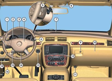
Cockpit
All instruments, switches, buttons and indicator/warning lamps in the passenger compartment needed for vehicle operation and monitoring.
Cold tire inflation pressure
(컄 page 386)
529
Technical terms
Collapsible tire
Engine number
FSS PLUS (Canada vehicles)
An especially compact spare tire that must be inflated with a provided air pump before using. It should only be used to bring the vehicle to the nearest service station.
Control system
The control system is used to call up vehicle information and to change component settings. Information and messages appear in the multifunction display. The driver uses the buttons on the multifunction steering wheel to navigate through the system and to ad- just settings. Cruise control
Driving convenience system for automatically maintaining the vehicle speed set by the driver.
Curb weight
(컄 page 386)
DOT
(Department of Transportation) (컄 page 386)
The number set by the manufacturer and placed on the cylinder block to uniquely identify each engine produced.
Engine oil viscosity
Measurement for the inner friction (vis- cosity) of the oil at different tempera- tures. The higher the temperature an oil can tolerate without becoming thin, or the lower the temperature it can tol- erate without becoming viscous, the better the viscosity.
ESP®
(Electronic Stability Program) Improves vehicle handling and direc- tional stability.
ETD
(Emergency Tensioning Device) Device which deploys in certain frontal and rear collisions exceeding the sys- tem's threshold to tighten the seat belts. ->SRS
(Flexible Service System PLUS) Maintenance service indicator in the speedometer display that informs the driver when the next vehicle mainte- nance service is due. FSS evaluates en- gine temperature, oil level, vehicle speed, engine speed, distance driven and the time elapsed since your last service, and calls for the next mainte- nance service accordingly.
GAWR
(Gross Axle Weight Rating) (컄 page 386)
Gear range
Number of gears which are available to the automatic transmission for shifting. The automatic gear shifting process can be adapted to specific operating conditions using the gear selector lever.
530
GPS
Kickdown
Maintenance System (U.S. vehicles)
Technical terms
(Global Positioning System) Satellite-based system for relaying geographic location information to and from vehicles equipped with special re- ceivers. Employs CD or DVD digital maps for navigation.
Depressing the accelerator past the point of resistance shifts the transmis- sion down to the lowest possible gear. This very quickly accelerates the vehi- cle and should not be used for normal acceleration needs.
GVW
(Gross Vehicle Weight) (컄 page 386)
GVWR
(Gross Vehicle Weight Rating) (컄 page 386)
Kilopascal (kPa) (컄 page 386)
Line of fall
The direct line that an object moves downhill when influenced by the force of gravity alone.
Instrument cluster
Locking knob
The displays and indicator/warning lamps in the driver’s field of vision, in- cluding the tachometer, speedometer, engine temperature and fuel gauge.
Knob on the door which indicates whether the door is locked or un- locked. Pushing the locking knob down on an individual door from inside will lock that door.
Maintenance service indicator in the multifunction display that informs the driver when the next vehicle mainte- nance service is due. The Maintenance system tracks distance driven and the time elapsed since the last mainte- nance service, calculates other mainte- nance service work required, and calls for the next service accordingly.
Maximum load rating
(컄 page 387)
Maximum loaded vehicle weight
(컄 page 387)
Maximum tire inflation pressure
(컄 page 387)
Modular COMAND System
Information and operating center for vehicle sound and communications systems, including the radio and the ra- dio and navigation system, as well as for other optional equipment (CD changer, telephone, etc.).
531
Technical terms
Memory function*
Used to store three individual seat, steering wheel and mirror positions.
Normal occupant weight
(컄 page 387)
Overspeed range
MON
(Motor Octane Number) The Motor Octane Number for gasoline as determined by a standardized meth- od. It is an indication of a gasoline's ability to resist undesired detonation (knocking). The average of both the MON (Motor Octane Number) and ->RON (Research Octane Number) is posted at the pump, also known as ANTI-KNOCK INDEX. Multifunction display
The display field in the instrument clus- ter used to present information provid- ed by the control system.
Multifunction steering wheel
Steering wheel with buttons for operat- ing the control system.
Engine speeds within the red marking on the tachometer dial. Avoid this en- gine speed range, as it may result in se- rious engine damage that is not covered by the Mercedes-Benz Limited Warranty.
Occupant distribution
(컄 page 387)
Parktronic (Parking assist)*
System which uses visual and acoustic signals to assist the driver during park- ing maneuvers. Poly-V-belt drive
Drives engine-components (alternator, AC compressor, etc.) from the engine.
Power train
Collective term designating all compo- nents used to generate and transmit motive power to the drive axles, includ- ing 앫 engine 앫 clutch/torque converter 앫 transmission 앫 transfer case 앫 drive shaft 앫 differential 앫 axle shafts/axles
PRE-SAFE®*
(Preventive Occupant Safety System) Vehicles equipped with PRE-SAFE®* take preventive measures when the system senses certain driving dynam- ics suggesting a possible accident.
Production options weight
(컄 page 387)
532
Program mode selector switch
RON
Used to switch the automatic transmis- sion between standard operation (S) and comfort operation (C).
PSI
(Pounds per square inch) (컄 page 387)
Recommended tire inflation pressure
(컄 page 387)
REST
(Residual Engine Heat Utilization) Feature that uses the engine heat stored in the coolant to heat the vehi- cle interior for a short time after the en- gine has been turned off.
Restraint system
Seat belts, belt tensioner, air bags and child seat restraint systems. As inde- pendent systems, their protective func- tions complement one another.
Rim
(컄 page 387)
(Research Octane Number) The Research Octane Number for gaso- line as determined by a standardized method. It is an indication of a gaso- line's ability to resist undesired detona- tion (knocking). The average of both the ->MON (Motor Octane Number) and RON (Research Octane Number) is posted at the pump, also known as ANTI-KNOCK INDEX.
Sidewall
(컄 page 387)
SRS
(Supplemental Restraint System) Seat belts, emergency tensioning de- vice and air bags. Though independent systems, they are closely interfaced to provide effective occupant protection.
Technical terms
Tele Aid System*
(Telematic Alarm Identification on Demand) The Tele Aid system consists of three types of response: automatic and man- ual emergency, roadside assistance and information. Tele Aid is initially ac- tivated by completing a subscriber agreement and placing an acquain- tance call. The Tele Aid system is operational pro- vided that the vehicle’s battery is charged, properly connected, not dam- aged and cellular and GPS coverage is available. Telematics*
A combination of the terms “telecom- munications” and “informatics”.
Tightening torque
Force times lever arm (e.g. a wheel wrench) with which threaded fasteners such as wheel bolts are tightened.
533
Technical terms
TIN
(Tire Identification Number) (컄 page 387) Tire load rating (컄 page 387)
Treadwear indicators
(컄 page 388)
TWR
(Tongue Weight Rating) (컄 page 388)
Tire ply composition and material used
(컄 page 388)
Uniform Tire Quality Grading Standards
(컄 page 388)
Tire speed rating
(컄 page 388)
Traction
(컄 page 388)
Transfer case
Speed of rotation/torque converter that works together with the ->auto- matic transmission.
Tread