- 2011 Jeep Wrangler Owners Manuals
- Jeep Wrangler Owners Manuals
- 2005 Jeep Wrangler Owners Manuals
- Jeep Wrangler Owners Manuals
- 2006 Jeep Wrangler Owners Manuals
- Jeep Wrangler Owners Manuals
- 2004 Jeep Wrangler Owners Manuals
- Jeep Wrangler Owners Manuals
- 2013 Jeep Wrangler Owners Manuals
- Jeep Wrangler Owners Manuals
- 2009 Jeep Wrangler Owners Manuals
- Jeep Wrangler Owners Manuals
- 2008 Jeep Wrangler Owners Manuals
- Jeep Wrangler Owners Manuals
- 2012 Jeep Wrangler Owners Manuals
- Jeep Wrangler Owners Manuals
- 2010 Jeep Wrangler Owners Manuals
- Jeep Wrangler Owners Manuals
- 2007 Jeep Wrangler Owners Manuals
- Jeep Wrangler Owners Manuals
- Download PDF Manual
-
the paired mobile phone to call the emergency num- ber. This feature is supported in the U.S., Canada, and Mexico.
button to begin.
NOTE: • The emergency number dialed is based on the country where the vehicle is purchased (911 for the U.S. and
UNDERSTANDING THE FEATURES OF YOUR VEHICLE 113
Canada and 060 for Mexico). The number dialed may not be applicable with the available mobile service and area. • If supported, this number may be programmable on button and say • The Uconnect™ Phone does slightly lower your chances of successfully making a phone call as to that for the mobile phone directly.some systems. To do this, press the “Setup”, followed by “Emergency”.
WARNING!
To use your Uconnect™ Phone System in an emer- gency, your mobile phone must be: • turned on, • paired to the Uconnect™ System, • and have network coverage.
114 UNDERSTANDING THE FEATURES OF YOUR VEHICLE Towing Assistance If you need towing assistance: • Press the • After the “Ready” prompt and the following beep, say
button to begin.
“Towing Assistance”.
NOTE: • The towing assistance number dialed is based on the country where the vehicle is purchased (1-800-528- 2069 for the U.S., 1-877-213-4525 for Canada, 55-14- 3454 for Mexico City and 1-800-712-3040 for outside Mexico City in Mexico). Please refer to the 24-Hour Towing Assistance coverage details on the DVD in the Warranty Information Booklet and the 24-Hour Tow- ing Assistance references. • If supported, this number may be programmable on button and say
some systems. To do this, press the “Setup”, followed by “Towing Assistance”.
Paging To learn how to page, refer to “Working with Automated Systems”. Paging works properly except for pagers of certain companies, which time out a little too soon to work properly with the Uconnect™ Phone. Voice Mail Calling To learn how to access your voice mail, refer to “Working with Automated Systems”. Working with Automated Systems This method is used in instances where one generally has to press numbers on the mobile phone keypad while navigating through an automated telephone system. You can use your Uconnect™ Phone to access a voice mail system or an automated service, such as a paging service or automated customer service line. Some ser- vices require immediate response selection. In some instances, the Uconnect™ Phone.
that may be too quick for use of
When calling a number with your Uconnect™ Phone that normally requires you to enter in a touch-tone sequence on your mobile phone keypad, you can press the button and say the sequence you wish to enter, followed by the word “Send”. For example, if required to enter your PIN followed with a pound, (3 7 4 6 #), you can button and say, “3 7 4 6 #Send”. Saying press the a number, or sequence of numbers, followed by “Send”, is also to be used for navigating through an automated customer service center menu structure, and to leave a number on a pager. You can also send stored Uconnect™ Phonebook entries as tones for fast and easy access to voice mail and pager entries. To use this feature, dial the number you wish to button and say, “Send”. The call and then press the system will prompt you to enter the name or number and say the name of the phonebook entry you wish to send.
UNDERSTANDING THE FEATURES OF YOUR VEHICLE 115
The Uconnect™ Phone will then send the corresponding phone number associated with the phonebook entry, as tones over the phone. NOTE: • You may not hear all of the tones due to mobile phone • Some paging and voice mail systems have system time out settings that are too short and may not allow the use of this feature.network configurations. This is normal.
Barge In - Overriding Prompts The “Voice Command” button can be used when you wish to skip part of a prompt and issue your voice command immediately. For example, if a prompt is asking “Would you like to pair a phone, clear a...,” you button and say, “Pair a Phone” to could press the select that option without having to listen to the rest of the voice prompt.
button to begin.
116 UNDERSTANDING THE FEATURES OF YOUR VEHICLE Turning Confirmation Prompts On/Off Turning confirmation prompts off will stop the system from confirming your choices (e.g., the Uconnect™ Phone will not repeat a phone number before you dial it). • Press the • After the “Ready” prompt and the following beep, say: − “Setup Confirmations Prompts On” − “Setup Confirmations Prompts Off” Phone and Network Status Indicators If available on the radio and/or on a premium display such as the instrument panel cluster, and supported by your mobile phone, the Uconnect™ Phone will provide notification to inform you of your phone and network status when you are attempting to make a phone call using Uconnect™ Phone. The status is given for roaming, network signal strength, phone battery strength, etc.
Dialing Using the Mobile Phone Keypad You can dial a phone number with your mobile phone keypad and still use the Uconnect™ Phone (while dialing via the mobile phone keypad, the user must exercise caution and take precautionary safety measures). By dialing a number with your paired Bluetooth威 mobile phone, the audio will be played through your vehicle’s audio system. The Uconnect™ Phone will work the same as if you dial the number using Voice Command. NOTE: Certain brands of mobile phones do not send the dial ring to the Uconnect™ Phone to play it on the vehicle audio system, so you will not hear it. Under this situa- tion, after successfully dialing a number the user may feel that the call did not go through even though the call is in progress. Once your call is answered, you will hear the audio.
Mute/Un-Mute (Mute OFF) When you mute the Uconnect™ Phone, you will still be able to hear the conversation coming from the other party, but the other party will not be able to hear you. In order to mute the Uconnect™ Phone: • Press the • Following the beep, say “Mute”. In order to un-mute the Uconnect™ Phone: • Press the • Following the beep, say “Mute off”. Advanced Phone Connectivity
button.
button.
Transfer Call to and from Mobile Phone The Uconnect™ Phone allows ongoing calls to be trans- ferred from your mobile phone to the Uconnect™ Phone without terminating the call. To transfer an ongoing call
UNDERSTANDING THE FEATURES OF YOUR VEHICLE 117
from your Uconnect™ Phone paired mobile phone to the Uconnect™ Phone or vice versa, press the button and say “Transfer Call”. Connect or Disconnect Link Between the Uconnect™ Phone and Mobile Phone Your mobile phone can be paired with many different electronic devices, but can only be actively ⬙connected⬙ with one electronic device at a time. If you would like to connect or disconnect the Bluetooth威 connection between a Uconnect™ Phone paired mobile phone and the Uconnect™ Phone, follow the instructions described in your mobile phone User’s Manual. List Paired Mobile Phone Names • Press the • After the “Ready” prompt and the following beep, saybutton to begin.
“Setup Phone Pairing”.
118 UNDERSTANDING THE FEATURES OF YOUR VEHICLE
• When prompted, say “List Phones”. • The Uconnect™ Phone will play the phone names of all paired mobile phones in order from the highest to the lowest priority. To “Select” or “Delete” a paired button and phone being announced, press the say “Select” or “Delete”. Also, see the next two sec- tions for an alternate way to “Select” or “Delete” a paired phone.
button to begin.
Select Another Mobile Phone This feature allows you to select and start using another phone paired with the Uconnect™ Phone. • Press the • After the “Ready” prompt and the following beep, say • You can also press the
button at any time while the list is being played, and then choose the phone that you wish to select.
“Setup Select Phone” and follow the prompts.
If
• The selected phone will be used for the next phone call. the Uconnect™ Phone will return to using the highest priority phone present in or near (approximately within 30 ft (9 m)) the vehicle.
the selected phone is not available,
button to begin.
“Setup Phone Pairing”.
Delete Uconnect™ Phone Paired Mobile Phones • Press the • After the “Ready” prompt and the following beep, say • At the next prompt, say “Delete” and follow the • You can also press the
button at any time while the list is being played, and then choose the phone you wish to delete.
prompts.
Things You Should Know About Your Uconnect™ Phone
Uconnect™ Phone Tutorial To hear a brief tutorial of the system features, press the
button and say “Uconnect™ Tutorial”.
Voice Training For users experiencing difficulty with the system recog- nizing their voice commands or numbers, the Uconnect™ Phone Voice Training feature may be used. To enter this training mode, follow one of the two following proce- dures: From outside the Uconnect™ Phone mode (e.g., from radio mode): • Press and hold the • Press the
button and say the “Voice Training, System Training, or Start Voice Training” command.
button for five seconds until
the session begins, or,
UNDERSTANDING THE FEATURES OF YOUR VEHICLE 119
You can either press the Uconnect™ Phone button to restore the factory setting or repeat the words and phrases when prompted by the Uconnect™ Phone. For best results, the Voice Training session should be com- pleted when the vehicle is parked with the engine running, all windows closed, and the blower fan switched off. This procedure may be repeated with a new user. The system will adapt to the last trained voice only. Reset • press the • After the “Ready” prompt, and the following beep, saybutton.
“Setup”, then “Reset”.
This will delete all phone pairing, phone book entries, and other settings in all language modes. The System will prompt you before resetting to factory settings.
120 UNDERSTANDING THE FEATURES OF YOUR VEHICLE Voice Command • For best performance, adjust the rearview mirror to provide at least 1⁄2 in (1 cm) gap between the overhead console (if equipped) and the mirror.
• Always wait for the beep before speaking. • Speak normally, without pausing, just as you would speak to a person sitting a few feet/meters away from you. • Make sure that no one other than you is speaking during a Voice Command period. • Performance is maximized under: • low-to-medium blower setting, • low-to-medium vehicle speed, • low road noise, • smooth road surface,
• fully closed windows, • dry weather condition. • Even though the system is designed for users speaking in North American English, French, and Spanish ac- cents, the system may not always work for some. • When navigating through an automated system such as voice mail, or when sending a page, at the end of speaking the digit string, make sure to say “Send”. • Storing names in the phonebook when the vehicle is • It is not recommended to store similar sounding • Phonebook (Downloaded and Uconnect™ Phone Lo- cal) name recognition rate is optimized when the entries are not similar.
names in the Uconnect™ Phonebook.
not in motion is recommended.
be spoken “eight-zero-zero” not “eight hundred”.
• Numbers must be spoken in single digits. “800” must • You can say “O” (letter “O”) for “0” (zero). • Even though international dialing for most number combinations is supported, some shortcut dialing number combinations may not be supported. • In a convertible vehicle, system performance may be
compromised with the convertible top down.
Far End Audio Performance • Audio quality is maximized under: • low-to-medium blower setting, • low-to-medium vehicle speed, • low road noise, • smooth road surface,
UNDERSTANDING THE FEATURES OF YOUR VEHICLE 121
• fully closed windows, • dry weather conditions, and • operation from the driver’s seat. • Performance, such as audio clarity, echo, and loudness to a large degree rely on the phone and network, and not the Uconnect™ Phone. • Echo at the phone far end can sometimes be reduced • In a convertible vehicle, system performance may be
by lowering the in-vehicle audio volume.
compromised with the convertible top down.
Recent Calls If your phone supports “Automatic Phonebook Down- load”, Uconnect™ Phone can list your Outgoing, Incom- ing and Missed Calls.
122 UNDERSTANDING THE FEATURES OF YOUR VEHICLE SMS Uconnect™ Phone can read or send new messages on your phone. Read Messages: If you receive a new text message while your phone is connected to Uconnect™ Phone, an announcement will be made to notify you that you have a new text message. If you wish to hear the new message: • Press the • After the “Ready” prompt and the following beep, say • Uconnect™ Phone will play the new text message for
“SMS Read” or “Read Messages”.
button.
you.
After reading a message, you can “Reply” or “Forward” the message using Uconnect™ Phone.
Send Messages: You can send messages using Uconnect™ Phone. To send a new message: • Press the • After the “Ready” prompt and the following beep, say • You can either say the message you wish to send or say
“SMS Send” or “Send Messages”.
button.
“List Messages”. There are 20 preset messages.
To send a message, press the system is listing the message and say “Send”. Uconnect™ Phone will prompt you to say the name or number of the person you wish to send the message to.
button while the
List of Preset Messages: 1. Yes 2. No 3. Where are you? 4. I need more direction. 5. L O L 6. Why 7. I love you 8. Call me 9. Call me later 10. Thanks
UNDERSTANDING THE FEATURES OF YOUR VEHICLE 123
11. See You in 15 minutes 12. I am on my way 13. I’ll be late 14. Are you there yet? 15. Where are we meeting? 16. Can this wait? 17. Bye for now 18. When can we meet 19. Send number to call 20. Start without me
124 UNDERSTANDING THE FEATURES OF YOUR VEHICLE Turn SMS Incoming Announcement ON/OFF Turning the SMS Incoming Announcement OFF will stop the system from announcing the new incoming mes- sages. • Press the • After the “Ready” prompt and the following beep, say “Setup, Incoming Message Announcement,” you will then be given a choice to change it.
button.
Bluetooth威 Communication Link Mobile phones have been found to lose connection to the Uconnect™ Phone. When this happens, the connection can generally be reestablished by switching the phone off/on. Your mobile phone is recommended to remain in Bluetooth威 ON mode. Power-Up After switching the ignition key from OFF to either the ON or ACC position, or after a language change, you must wait at least five seconds prior to using the system.
UNDERSTANDING THE FEATURES OF YOUR VEHICLE 125
126 UNDERSTANDING THE FEATURES OF YOUR VEHICLE
UNDERSTANDING THE FEATURES OF YOUR VEHICLE 127
128 UNDERSTANDING THE FEATURES OF YOUR VEHICLE
Voice Commands
Alternate(s)
Primary zero one two three four five six seven eight nine star (*) plus (+) pound (#) add location all
Voice Commands
Alternate(s)
Primary call cancel confirmation prompts continue delete dial download edit emergency English erase all Espanol Francais help home
Voice Commands
Alternate(s)
pairing phone book
Primary language list names list phones mobile mute mute off new entry no pager pair a phone phone pairing phonebook previous record again redial
UNDERSTANDING THE FEATURES OF YOUR VEHICLE 129
Voice Commands
Alternate(s) return or main menu select
phone settings or phone set up
Primary return to main menu select phone send set up
towing assistance transfer call Uconnect™ Tutorial try again voice training work yes
130 UNDERSTANDING THE FEATURES OF YOUR VEHICLE General Information This device complies with Part 15 of the FCC rules and RSS 210 of Industry Canada. Operation is subject to the following conditions: • Changes or modifications not expressly approved by the party responsible for compliance could void the user’s authority to operate the equipment.
• This device may not cause harmful interference. • This device must accept any interference received, including interference that may cause undesired operation.
VOICE COMMAND — IF EQUIPPED
Voice Command System Operation
This Voice Command system allows you to control your AM, FM radio, satellite radio, disc player, and a memo recorder.
NOTE: Take care to speak into the Voice Interface System as calmly and normally as possible. The ability of the Voice Interface System to recognize user voice com- mands may be negatively affected by rapid speaking or a raised voice level.
WARNING!
Any voice commanded system should be used only in safe driving conditions following local laws. All attention should be kept on the roadway ahead. Failure to do so may result in a collision causing serious injury or death.
button, you When you press the Voice Command will hear a beep. The beep is your signal to give a command. If you do not say a command within a few NOTE: seconds, the system will present you with a list of options.
If you ever wish to interrupt the system while it lists button, listen options, press the Voice Command for the beep, and say your command. button while the Pressing the Voice Command system is speaking is known as “barging in.” The system will be interrupted, and after the beep, you can add or change commands. This will become helpful once you start to learn the options. NOTE: At any time, you can say the words “Cancel”, “Help” or “Main Menu”. These commands are universal and can be used from any menu. All other commands can be used depending upon the active application. When using this system, you should speak clearly and at a normal speaking volume.
UNDERSTANDING THE FEATURES OF YOUR VEHICLE 131
The system will best recognize your speech if the win- dows are closed, and the heater/air conditioning fan is set to low. At any point, if the system does not recognize one of your commands, you will be prompted to repeat it. To hear the first available Menu, press the Voice Com- mand Commands The Voice Command system understands two types of commands. Universal commands are available at all times. Local commands are available if the supported radio mode is active. Changing the Volume 1. Start a dialogue by pressing the Voice Commandbutton and say “Help” or “Main Menu”.
button.
2. Say a command (e.g., “Help”).
132 UNDERSTANDING THE FEATURES OF YOUR VEHICLE 3. Use the ON/OFF VOLUME rotary knob to adjust the volume to a comfortable level while the Voice Command system is speaking. Please note the volume setting for Voice Command is different than the audio system. Main Menu Start a dialogue by pressing the Voice Command button. You may say “Main Menu” to switch to the main menu. In this mode, you can say the following commands: • “Radio” (to switch to the radio mode) • “Disc” (to switch to the disc mode) • “Memo” (to switch to the memo recorder) • “Setup” (to switch to system setup)
Radio AM To switch to the AM band, say “AM” or “Radio AM”. In this mode, you may say the following commands: • “Frequency #” (to change the frequency) • “Next Station” (to select the next station) • “Previous Station” (to select the previous station) • “Radio Menu” (to switch to the radio menu) • “Main Menu” (to switch to the main menu) Radio FM To switch to the FM band, say “FM” or “Radio FM”. In this mode, you may say the following commands: • “Frequency #” (to change the frequency) • “Next Station” (to select the next station) • “Previous Station” (to select the previous station)
• “Menu Radio” (to switch to the radio menu) • “Main Menu” (to switch to the main menu) Satellite Radio To switch to satellite radio mode, say “Sat” or “Satellite Radio”. In this mode, you may say the following com- mands: • “Channel Number” (to change the channel by its • “Next Channel” (to select the next channel) • “Previous Channel” (to select the previous channel) • “List Channel” (to hear a list of available channels) • “Select Name” (to say the name of a channel) • “Menu Radio” (to switch to the radio menu) • “Main Menu” (to switch to the main menu)
spoken number)
UNDERSTANDING THE FEATURES OF YOUR VEHICLE 133
Disc To switch to the disc mode, say “Disc”. In this mode, you may say the following commands: • “Track” (#) (to change the track) • “Next Track” (to play the next track) • “Previous Track” (to play the previous track) • “Main Menu” (to switch to the main menu) Memo To switch to the voice recorder mode, say “Memo”. In this mode, you may say the following commands: • “New Memo” (to record a new memo) — During the
recording, you may press the Voice Command button to stop recording. You proceed by saying one of the following commands: − “Save” (to save the memo)
134 UNDERSTANDING THE FEATURES OF YOUR VEHICLE
− “Continue” (to continue recording) − “Delete” (to delete the recording) • “Play Memos” (to play previously recorded memos) — During the playback you may press the Voice button to stop playing memos. You Command proceed by saying one of the following commands: − “Repeat” (to repeat a memo) − “Next” (to play the next memo) − “Previous” (to play the previous memo) − “Delete” (to delete a memo) • “Delete All” (to delete all memos) Setup To switch to system setup, you may say on of the following: • “Change to setup”
• “Switch to system setup” • “Change to setup” • “Main menu setup” or • “Switch to setup” In this mode, you may say the following commands: • “Language English” • “Language French” • “Language Spanish” • “Tutorial” • “Voice Training” NOTE: Keep in mind that you have to press the Voice button first and wait for the beep before Command speaking the “Barge In” commands.
Voice Training For users experiencing difficulty with the system recog- nizing their voice commands or numbers the Uconnect™ Voice “Voice Training” feature may be used. button, say “System 1. Press the Voice Command Setup” and once you are in that menu then say “Voice Training.” This will train your own voice to the system and will improve recognition. 2. Repeat the words and phrases when prompted by Uconnect™ Voice. For best results, the “Voice Training” session should be completed when the vehicle is parked, engine running, all windows closed, and the blower fan switched off. This procedure may be repeated with a new user. The system will adapt to the last trained voice only.
SEATS Seats are part of the Occupant Restraint System of the vehicle.
UNDERSTANDING THE FEATURES OF YOUR VEHICLE 135
WARNING!
• It is dangerous to ride in a cargo area, inside or outside of a vehicle. In a collision, people riding in these areas are more likely to be seriously injured or killed. • Do not allow people to ride in any area of your vehicle that is not equipped with seats and seat belts. In a collision, people riding in these areas are more likely to be seriously injured or killed. • Be sure everyone in your vehicle is in a seat and
using a seat belt properly.
Front Seat Adjustment The seat can be adjusted forward or rearward by using a bar located by the front of the seat cushion, near the floor. While sitting in the seat, lift up on the bar located under the seat cushion and move the seat forward or rearward. Release the bar once you have reached the desired
136 UNDERSTANDING THE FEATURES OF YOUR VEHICLE position. Then, using body pressure, move forward and rearward on the seat to be sure that the seat adjusters have latched.
Manual Seat Adjustment
WARNING!
• Adjusting a seat while driving may be dangerous. Moving a seat while driving could result in loss of control which could cause a collision and serious injury or death. • Seats should be adjusted before fastening the seat belts and while the vehicle is parked. Serious injury or death could result from a poorly adjusted seat belt.
Manual Seat Height Adjustment — If Equipped The driver’s seat height can be raised or lowered by using the ratcheting handle, located on the outboard side of the seat. Pull upward on the handle to raise the seat; push downward on the handle to lower the seat.
UNDERSTANDING THE FEATURES OF YOUR VEHICLE 137
Seat Height Adjustment
Front Seatback Recline Lean forward before lifting the handle, then lean back to the desired position and release the handle. Lift the handle to return the seatback to an upright position.
Recline Lever
WARNING!
Do not ride with the seatback reclined so that the shoulder belt is no longer resting against your chest. In a collision you could slide under the seat belt, which could result in serious injury or death.
138 UNDERSTANDING THE FEATURES OF YOUR VEHICLE Front Passenger Easy Entry Seat — Two-Door Models Pull upward on the recline lever (toward the rear of the vehicle) and slide the entire seat forward.
Easy Entry Seat
To return the seat to a sitting position, rotate the seatback upright until it locks and push the seat rearward until the track locks.
Easy Entry Lever
NOTE: • The front passenger seats have a track memory, which returns the seat to just past the halfway point of the track regardless of its original position. • The recliner and easy entry levers should not be used during the automatic returning of the seat to its sitting position.
Tip n’ Slide Seats — Two-Door Models This feature allows the front seats to be rotated toward the instrument panel to allow easier entry into the rear seats.
UNDERSTANDING THE FEATURES OF YOUR VEHICLE 139
Driver’s Seat Pull upward on the recline lever and bring the seatback to its full forward position.
Recline Lever
140 UNDERSTANDING THE FEATURES OF YOUR VEHICLE Rotate the entire seat assembly toward the instrument panel.
Pull upward on the recline lever and slide the entire seat forward (Easy Entry).
Tip n’ Slide
Easy Entry Lever
Passenger Seat In addition to Easy Entry, the front passenger seat is also equipped with Tip n’ Slide. This feature allows for easier entry for rear passengers.
With the seat forward, pull the entire seat assembly toward the instrument panel.
UNDERSTANDING THE FEATURES OF YOUR VEHICLE 141
controls for each seat are located on a switch bank near the bottom center of the instrument panel. You can choose from HIGH, LOW or OFF heat settings. Amber indicator lights in each switch indicate the level of heat in use. Two indicator lights will illuminate for HIGH, one for LOW and none for OFF.Press the switch once to select HIGH-level heating. Press the switch a second time to select LOW-level heating. Press the switch a third time to shut the heating elements OFF.
When the HIGH-level setting is selected, the heater will provide a boosted heat level during the first four minutes of operation. Then, the heat output will drop to the normal HIGH-level. If the HIGH-level setting is selected, the system will automatically switch to LOW-level after approximately 30 minutes of continuous operation. At that time, the number of illuminated LEDs changes from
Tip n’ Slide
Heated Seats — If Equipped On some models, the front driver and passenger seats may be equipped with heaters in both the seat cushions and seatbacks. There are two heated seat switches that allow the driver and passenger to operate the seats independently. The
142 UNDERSTANDING THE FEATURES OF YOUR VEHICLE two to one, indicating the change. The LOW-level setting will turn OFF automatically after approximately 30 min- utes. NOTE: When a heat setting is selected, heat will be felt within two to five minutes.
WARNING!
• Persons who are unable to feel pain to the skin because of advanced age, chronic illness, diabetes, spinal cord injury, medication, alcohol use, ex- haustion or other physical condition must exercise care when using the seat heater. It may cause burns even at low temperatures, especially if used for long periods of time.
(Continued)
WARNING! (Continued)
• Do not place anything on the seat that insulates against heat, such as a blanket or cushion. This may cause the seat heater to overheat. Sitting in a seat that has been overheated could cause serious burns due to the increased surface temperature of the seat.
Head Restraints Head restraints are designed to reduce the risk of injury by restricting head movement in the event of a rear impact. Head restraints should be adjusted so that the top of the head restraint is located above the top of your ear.
WARNING!
The head restraints for all occupants must be prop- erly adjusted prior to operating the vehicle or occu- pying a seat. Head restraints should never be ad- justed while the vehicle is in motion. Driving a vehicle with the head restraints improperly adjusted or removed could cause serious injury or death in the event of a collision.
Front Head Restraints To raise the head restraint, pull upward on the head restraint. To lower the head restraint, press the adjust- ment button, located on the base of the head restraint, and push downward on the head restraint.
UNDERSTANDING THE FEATURES OF YOUR VEHICLE 143
Adjustment Button
Rear Head Restraints The rear seat is equipped with nonadjustable head re- straints. Refer to “Occupant Restraints” in “Things to Know Before Starting Your Vehicle” for information on child seat tether routing.
144 UNDERSTANDING THE FEATURES OF YOUR VEHICLE Fold And Tumble Rear Seat — Two-Door Models NOTE: • Prior to folding the rear seat, it may be necessary to • Be sure that the front seats are fully upright and positioned forward. This will allow the rear seat to fold down easily.
reposition the front seats.
1. Lift the seatback release lever and fold the seatback forward.
Rear Seat Release 2. Slowly flip the entire seat forward.
UNDERSTANDING THE FEATURES OF YOUR VEHICLE 145
Removing The Rear Seat — Two-Door Models
WARNING!
• It is extremely dangerous to ride in a cargo area, inside or outside of a vehicle. In a collision, people riding in these areas are more likely to be seri- ously injured or killed. • Do not allow people to ride in any area of your vehicle that is not equipped with seats and seat belts. • Be sure everyone in your vehicle is in a seat and • In a collision, you or others in your vehicle could be injured if seats are not properly latched to their floor attachments. Always be sure that the seats are fully latched.
using a seat belt properly.
1. Fold the rear seat forward following steps 1 and 2
under “Fold And Tumble Rear Seat” in this section.Folding Rear Seat
3. Return the seat to the normal position. 4. Raise the rear seatback using the assist strap and firmly lock the seat into position.
146 UNDERSTANDING THE FEATURES OF YOUR VEHICLE 2. Press down on the release bar on each side, and pull the seat out and away from the lower bracket. 3. Remove the seat from the vehicle.
Release Bar Location
Replacing The Rear Seat — Two-Door Models Reverse the steps for removing the seat.
WARNING!
• To help protect against personal injury, passengers should not be seated in the rear cargo area with the rear seat folded down or removed from the ve- hicle. • The rear cargo space is intended for load carrying purposes only, not for passengers who should sit in seats and use seat belts.
60/40 Split Folding Rear Seat — Four-Door Models To provide additional storage area, each rear seat can be folded flat to allow for extended cargo space and still maintain some rear seating room.
reposition the front seat to its mid-track position.
NOTE: • Prior to folding the rear seat, it may be necessary to • Be sure that the front seats are fully upright and positioned forward. This will allow the rear seat to fold down easily.
WARNING!
• It is extremely dangerous to ride in a cargo area, inside or outside of a vehicle. In a collision, people riding in these areas are more likely to be seri- ously injured or killed. • Do not allow people to ride in any area of your vehicle that is not equipped with seats and seat belts. • Be sure everyone in your vehicle is in a seat and
using a seat belt properly.
UNDERSTANDING THE FEATURES OF YOUR VEHICLE 147
To Fold Down The Rear Seat Locate the pull strap (lower outboard side of seat), and pull it toward you until the seatback releases.
Pull Strap
148 UNDERSTANDING THE FEATURES OF YOUR VEHICLE To Raise The Rear Seat Raise the seatback and lock it into place. If interference from the cargo area prevents the seatback from fully locking, you will have difficulty returning the seat to its proper position. If the rear seatback is not fully latched, the NOTE: center shoulder belt will not be able to be extended for use. If you cannot extend the center shoulder belt, make sure your seatback is fully latched.
WARNING!
Be certain that the seatback is securely locked into position. If the seatback in not securely locked into position the seat will not provide the proper stability for child seats and/or passengers. An improperly latched seat could cause serious injury.
TO OPEN AND CLOSE THE HOOD Release both the hood latches.
Hood Latch
Raise the hood and locate the safety latch, located in the middle of the hood opening. Push the latch to the left side of the vehicle, to open the hood. You may have to push down slightly on the hood before pushing the safety latch. Insert the support rod into the slot on the hood.
UNDERSTANDING THE FEATURES OF YOUR VEHICLE 149
Multifunction Lever
To close the hood, remove the support rod from the hood panel and place it in the retaining clip. Lower the hood slowly. Secure both of the hood latches.
WARNING!
Be sure the hood is fully latched before driving your vehicle. If the hood is not fully latched, it could open when the vehicle is in motion and block your vision. Failure to follow this warning could result in serious injury or death.
LIGHTS
Multifunction Lever The multifunction lever controls the operation of the parking lights, headlights, headlight beam selection, passing light, fog lights, instrument panel light dimming and turn signals. The lever is located on the left side of the steering column.
150 UNDERSTANDING THE FEATURES OF YOUR VEHICLE Headlights And Parking Lights Turn the end of the multifunction lever to the first detent for parking lights and instrument panel lights. Turn to the second detent for headlight operation.
NOTE: Lens fogging can occur under certain weather conditions. Turning the headlights on will usually accel- erate the clearing process. Automatic Headlights — If Equipped This system automatically turns the headlights on or off according to the ambient light levels. To turn the system on, turn the end of the multifunction lever to the AUTO position (third detent). When the system is on, the Headlight Time Delay feature is also on. This means the headlights will stay on for 90 seconds after you turn the ignition switch to the LOCK position. To turn the Auto- matic System off, turn the end of the multifunction lever out of the AUTO position.
Headlight Switch
UNDERSTANDING THE FEATURES OF YOUR VEHICLE 151
Headlight Switch
Turn Signal Operation
NOTE: The engine must be running before the head- lights will turn on in the Automatic mode. Turn Signals Move the multifunction lever up or down and the arrows on each side of the instrument cluster flash to show proper operation of the front and rear turn signal lights.
NOTE: • If either light remains on and does not flash, or there is a very fast flash rate, check for a defective outside light bulb. If an indicator fails to light when the lever is moved, it would suggest that the indicator bulb is defective.
152 UNDERSTANDING THE FEATURES OF YOUR VEHICLE
• A tone will chime if the turn signals are left on for
more than 1 mile (2 km).
Lane Change Assist Tap the lever up or down once, without moving beyond the detent, and the turn signal (right or left) will flash three times then automatically turn off. Lights-On Reminder If the headlights or parking lights are on after the ignition is turned OFF, a chime will sound when the driver’s door is opened. High/Low Beam Switch Push the multifunction lever away from you to switch the headlights to high beam. Pull the lever toward you to switch the headlights back to low beam.
Flash-To-Pass You can signal another vehicle with your headlights by lightly pulling the multifunction lever toward the steer- ing wheel. This will turn on the high beam headlights until the lever is released. Front Fog Lights
The front fog light switch is located on the multi- function lever. To activate the front fog lights, turn on the parking or low beam headlights and pull
out the end of the lever. NOTE: The fog lights will only operate with the parking lights or the headlights on low beam. Selecting high beam headlights will turn off the fog lights.
Instrument Panel Dimmer Rotate the center portion of the lever to the extreme bottom position to fully dim the instrument panel lights and prevent the interior lights from illuminating when a door is opened. Rotate the center portion of the lever up to increase the brightness of the instrument panel lights when the park- ing lights or headlights are on. Rotate the center portion of the lever upward to the next detent position to brighten the odometer and radio when the parking lights or headlights are on. Rotate the center portion of the lever upward to the last detent to turn on the interior lighting.
UNDERSTANDING THE FEATURES OF YOUR VEHICLE 153
Dimmer Control
Daytime Running Lights — If Equipped The headlights come on at a low intensity level when shifted into any position other than PARK (auto trans- mission) or when the vehicle begins to move (manual transmission).
154 UNDERSTANDING THE FEATURES OF YOUR VEHICLE NOTE: The Daytime Running Light on the same side of the vehicle as the active turn signal will turn off auto- matically when a turn signal is in operation and turn on again when the turn signal is not operating. Interior Lights The overhead light will turn on when a door is opened. It may also be turned on by rotating the control for the dimmer switch on the multifunction lever fully upward. The overhead light will automatically turn off in approxi- mately 10 minutes if a door is left open or the dimmer control is left in the dome light position. Turn the ignition switch ON to restore the overhead light operation. Cargo Lamp The courtesy and dome lights will turn on when the front doors are opened, by rotating the control for the dimmer switch on the multifunction lever fully upward, or if equipped, when the UNLOCK button is pressed on the Remote Keyless Entry (RKE) transmitter.
The sports bar reading lights (available on four-door models) can be turned on by pressing the switches, located on either side of the lens. Press a switch a second time to turn the light off.
Sports Bar Reading Light
The rear cargo light may be turned on by pressing the lens. Press the lens a second time to turn the light off.
UNDERSTANDING THE FEATURES OF YOUR VEHICLE 155
WINDSHIELD WIPERS AND WASHERS The windshield wiper/washer control lever is located on the right side of the steering column. The front wipers are operated by rotating a switch, located at the end of the lever. For information on using the rear window wiper/ washer, refer to “Rear Window Features” in “Under- standing The Features Of Your Vehicle”.
Rear Cargo Light
When a door is open and the interior lights are on, rotating the dimmer control to the extreme bottom posi- tion will cause all the interior lights to turn off. This is also known as the “Party” mode because it allows the doors to stay open for extended periods of time without discharging the vehicle’s battery.
Windshield Wiper/Washer Lever
156 UNDERSTANDING THE FEATURES OF YOUR VEHICLE Windshield Wiper Operation Rotate the end of the lever upward to the second detent past the intermittent settings for low-speed wiper opera- tion. Rotate the end of the lever upward to the third detent past the intermittent settings for high-speed wiper opera- tion.
CAUTION!
In cold weather, always turn off the wiper switch and allow the wipers to return to the park position before turning off the engine. If the wiper switch is left on and the wipers freeze to the windshield, damage to the wiper motor may occur when the vehicle is restarted.
Intermittent Wiper System Use the intermittent wiper when weather conditions make a single wiping cycle, with a variable pause be- tween cycles, desirable. Rotate the end of the lever to the first detent position for one of five intermittent settings. The delay cycle can be set anywhere between 1 to 18 seconds.
Front Wiper Control
UNDERSTANDING THE FEATURES OF YOUR VEHICLE 157
delay range, the wiper will start and continue to operate for two or three wipe cycles after the lever is released, and then resume the intermittent interval previously selected. If the lever is pulled while in the off position, the wipers will operate for two or three wipe cycles and then turn off.WARNING!
Sudden loss of visibility through the windshield could lead to a collision. You might not see other vehicles or other obstacles. To avoid sudden icing of the windshield during freezing weather, warm the windshield with defroster before and during wind- shield washer use.
Front Wiper Control
NOTE: The wiper delay times depend on vehicle speed. If the vehicle is moving less than 10 mph (16 km/h), delay times will be doubled. Windshield Washers To use the washer, pull the lever toward you and hold while spray is desired. If the lever is pulled while in the
158 UNDERSTANDING THE FEATURES OF YOUR VEHICLE Mist Feature Push down on the wiper lever to activate a single wipe to clear off road mist or spray from a passing vehicle. As long as the lever is held down, the wipers will continue to operate. NOTE: The mist feature does not activate the washer pump; therefore, no washer fluid will be sprayed on the windshield. The wash function must be used in order to spray the windshield with washer fluid.
Mist Control
TILT STEERING COLUMN This feature allows you to tilt the steering column upward or downward. The tilt lever is located on the steering column, below the turn signal lever.
Push down on the lever to unlock the steering column. With one hand firmly on the steering wheel, move the steering column up or down, as desired. Pull upwards on the lever to lock the column firmly in place.
UNDERSTANDING THE FEATURES OF YOUR VEHICLE 159
WARNING!
Do not adjust the steering column while driving. Adjusting the steering column while driving or driv- ing with the steering column unlocked, could cause the driver to lose control of the vehicle. Be sure the steering column is locked before driving your ve- hicle. Failure to follow this warning may result in serious injury or death.
ELECTRONIC SPEED CONTROL — IF EQUIPPED When engaged, the Electronic Speed Control takes over accelerator operations at speeds greater than 25 mph (40 km/h).
Tilt Steering Column Lever
160 UNDERSTANDING THE FEATURES OF YOUR VEHICLE The Electronic Speed Control buttons are located on the right side of the steering wheel.
2 — RES + 3 — SET -
1 — ON/OFF 4 — CANCEL In order to ensure proper operation, the Elec- NOTE: tronic Speed Control System has been designed to shut down if multiple Speed Control functions are operated at
the same time. If this occurs, the Electronic Speed Control System can be reactivated by pushing the Electronic Speed Control ON/OFF button and resetting the desired vehicle set speed. To Activate Push the ON/OFF button. The Cruise Indicator Light in the instrument cluster will illuminate. To turn the system off, push the ON/OFF button a second time. The Cruise Indicator Light will turn off. The system should be turned off when not in use.
WARNING!
Leaving the Electronic Speed Control system on when not in use is dangerous. You could accidentally set the system or cause it to go faster than you want. You could lose control and have an accident. Always leave the system OFF when you are not using it.
To Set A Desired Speed Turn the Electronic Speed Control ON. When the vehicle has reached the desired speed, press the SET (-) button and release. Release the accelerator and the vehicle will operate at the selected speed. NOTE: The vehicle should be traveling at a steady speed and on level ground before pressing the SET button. To Deactivate A soft tap on the brake pedal, pushing the CANCEL button, or normal brake pressure while slowing the vehicle will deactivate Electronic Speed Control without erasing the set speed memory. Pressing the ON/OFF button or turning the ignition switch OFF erases the set speed memory.
UNDERSTANDING THE FEATURES OF YOUR VEHICLE 161
To Resume Speed To resume a previously set speed, push the RES (+) button and release. Resume can be used at any speed above 20 mph (32 km/h). To Vary The Speed Setting When the Electronic Speed Control is set, you can in- crease speed by pushing the RES (+) button. If the button is continually pressed, the set speed will continue to increase until the button is released, then the new set speed will be established. Pressing the RES (+) button once will result in a 1 mph (2 km/h) increase in set speed. Each subsequent tap of the button results in an increase of 1 mph (2 km/h). To decrease speed while the Electronic Speed Control is set, push the SET (-) button. If the button is continually held in the SET (-) position, the set speed will continue to
162 UNDERSTANDING THE FEATURES OF YOUR VEHICLE decrease until the button is released. Release the button when the desired speed is reached, and the new set speed will be established. Pressing the SET (-) button once will result in a 1 mph (2 km/h) decrease in set speed. Each subsequent tap of the button results in a decrease of 1 mph (2 km/h). To Accelerate For Passing Press the accelerator as you would normally. When the pedal is released, the vehicle will return to the set speed. Using Electronic Speed Control On Hills The transmission may downshift on hills to maintain the vehicle set speed. NOTE: The Electronic Speed Control system maintains speed up and down hills. A slight speed change on moderate hills is normal.
On steep hills, a greater speed loss or gain may occur so it may be preferable to drive without Electronic Speed Control.
WARNING!
Electronic Speed Control can be dangerous where the system cannot maintain a constant speed. Your ve- hicle could go too fast for the conditions, and you could lose control and have an accident. Do not use Electronic Speed Control in heavy traffic or on roads that are winding, icy, snow-covered or slippery.
ELECTRICAL POWER OUTLET There are two 12 Volt (13 Amp) auxiliary power outlets that can provide power for accessories designed for use with the standard power outlet adapters.
The front power outlet is powered from the ignition switch. Power is available when the ignition switch is in the ON or ACC position.
Front Power Outlet
When the optional cigar lighter heating element is used in the power outlet, it heats when pushed in and pops out
UNDERSTANDING THE FEATURES OF YOUR VEHICLE 163
automatically when ready for use. To preserve the heat- ing element, do not hold the lighter in the heating position. A second power outlet is located inside the center console and is powered directly from the vehicle battery.CAUTION!
• Do not exceed the maximum power of 160 Watts (13 Amps) at 12 Volts. If the 160 Watt (13 Amp) power rating is exceeded the fuse protecting the system will need to be replaced. • Power outlets are designed for accessory plugs only. Do not insert any other object in the power outlets as this will damage the outlet and blow the fuse. Improper use of the power outlet can cause damage not covered by your New Vehicle Limited Warranty.
164 UNDERSTANDING THE FEATURES OF YOUR VEHICLE On vehicles equipped with a rear subwoofer, there is a third power outlet located in the right rear cargo area.
Rear Power Outlet — If Equipped
Power Outlet Fuse Locations
1 — M7 Fuse 20 A Yellow Power Outlet Rear with Sub Woofer (Opt.) 2 — M6 Fuse 20 A Yellow Cigar Lighter Instrument Panel 3 — M36 Fuse 20 A Yellow Power Outlet Console Bin
WARNING!
To avoid serious injury or death: • Only devices designed for use in this type of outlet should be inserted into any 12 Volt outlet. • Do not touch with wet hands. • Close the lid when not in use and while driving • If this outlet is mishandled, it may cause an
the vehicle.
electric shock and failure.
UNDERSTANDING THE FEATURES OF YOUR VEHICLE 165
CAUTION!
• Many accessories that can be plugged in draw power from the vehicle’s battery, even when not in use (i.e., mobile phones, etc.). Eventually, if plugged in long enough, the vehicle’s battery will discharge sufficiently to degrade battery life and/or prevent the engine from starting. • Accessories that draw higher power (i.e., coolers, vacuum cleaners, lights, etc.), will degrade the battery even more quickly. Only use these inter- mittently and with greater caution. • After the use of high-power draw accessories, or long periods of the vehicle not being started (with accessories still plugged in), the vehicle must be driven a sufficient length of time to allow the alternator to recharge the vehicle’s battery.
(Continued)
166 UNDERSTANDING THE FEATURES OF YOUR VEHICLE
CAUTION! (Continued)
• Power outlets are designed for accessory plugs only. Do not hang any type of accessory or acces- sory bracket from the plug.
POWER INVERTER — IF EQUIPPED There is a 115 Volt, 150 Watt inverter outlet located on the front of the center console to convert DC current to AC current. This outlet can power cellular phones, electron- ics and other low power devices requiring power up to 150 Watts. Certain high-end video games, such as Play- station3 and XBox360 will exceed this power limit, as will most power tools.
Power Inverter
The power inverter is designed with built-in overload protection. If the power rating of 150 Watts is exceeded, the power inverter will automatically shut down. Once the electrical device has been removed from the outlet the inverter should automatically reset. If the power rating exceeds approximately 170 Watts, the power inverter
may have to be reset manually. To reset the inverter manually press the power inverter button OFF and ON. To avoid overloading the circuit, check the power ratings on electrical devices prior to using the inverter.
The power inverter switch is located on the instrument panel below the climate controls. To turn on the power outlet, press the switch once. The in- dicator light will illuminate. Press the switch a second time to turn the power inverter outlet off.
NOTE: When the power inverter switch is pressed, there will be a delay of approximately one second before the inverter indicator light turns ON.
UNDERSTANDING THE FEATURES OF YOUR VEHICLE 167
WARNING!
To avoid serious injury or death: • Do not use a three-prong adaptor. • Do not insert any objects into the receptacles. • Do not touch with wet hands. • Close the lid when not in use. • If this outlet is mishandled it may cause an electric
shock and failure.
168 UNDERSTANDING THE FEATURES OF YOUR VEHICLE CUPHOLDERS
Front Cupholders The front cupholders are located in the center console.
Rear Cupholders The rear cupholders are located on the back of the center console.
Front Cupholders
Rear Cupholders
STORAGE
Glovebox Storage The lockable glovebox storage compartment is located on the passenger side of the lower instrument panel. Pull outward on the handle/latch to open the compartment. Console Storage Compartment To lock or unlock the storage compartment, insert the ignition key and turn. To open the storage compartment, press the latch and lift the cover.
UNDERSTANDING THE FEATURES OF YOUR VEHICLE 169
Center Console
Rear Storage Compartment The rear cargo area storage compartment cover is held by a spring-loaded latch. In order to remove the rear storage compartment cover, use the following procedure: NOTE: The rear storage compartment latch should not be used as cargo tie-down.
170 UNDERSTANDING THE FEATURES OF YOUR VEHICLE 1. Flip up the pull loop so it is perpendicular (straight up) to the top surface of the tray. 2. Pull up on the loop and twist it 90 degrees, so it is parallel to the slotted hole in the tray. 3. Open the rear compartment cover.
Rear Storage Cover
DUAL TOP — IF EQUIPPED If your vehicle is equipped with a Dual Top, you must remove one of the tops from the vehicle. If the soft top is removed, the pivot brackets must also be removed from the sport bar. The soft top was installed at the factory for shipping purposes only. The soft top and the hard top are to be used independently. Removal is mandatory to prevent any possible wear and tear on the soft top. Your vehicle warranty will not cover damage resulting from both tops remaining on the vehicle at the same time for extended periods of time. Removing The Soft Top
1. Locate and remove the two boxes that contain the following items: • Right and left door frames • Door frame attachment knobs (four for two-door
models, six for four-door models)
• Right and left quarter windows • Rear window • Two rear window roll up straps • Two Sunrider威 secure straps (if equipped) • Two rear swing gate brackets 2. Remove the hard top. Refer to “Freedom Top Three- Piece Modular Hard Top — Front/Rear Panel Removal” in this section. 3. Remove the soft top bow assembly pivot bracket screws (two per side) using a #T30 Torx威 head driver.
UNDERSTANDING THE FEATURES OF YOUR VEHICLE 171
4. Disconnect the knuckles from the left and right metal pivot brackets. Remove the soft top from the vehicle and store in a clean, dry location.
172 UNDERSTANDING THE FEATURES OF YOUR VEHICLE NOTE: To aid in disconnecting the knuckles, you may carefully tap on the knuckles using a rubber mallet.
5. Unzip the zipper on the sport bar cover to expose the pivot brackets. Remove the brackets using a #T30 Torx威 head driver. Recover and re-zip the sports bar cover. Store the pivot brackets and screws in a safe place.
6. Reinstall the hard top. Refer to “Freedom Top Three- Piece Modular Hard Top — Front/Rear Panel Installa- tion” in this section.
Installing The Soft Top
NOTE: The following procedures are for first time set up only. For future soft top procedures, refer to “Soft Top” in this section. 1. Locate and remove the following items prior to hard top removal: • Right and left door frames • Door frame attachment knobs (four for two-door models, six for four-door models) • Right and left quarter windows
UNDERSTANDING THE FEATURES OF YOUR VEHICLE 173
• Rear window 2. Remove the hard top. Refer to “Freedom Top Three- Piece Modular Hard Top — Front/Rear Panel Removal” in this section. 3. Install the door frames. Refer to “Door Frame” in this section. 4. If the soft top has been removed, follow these steps to reinstall the soft top. If the soft top is on the vehicle, proceed to step #5.
174 UNDERSTANDING THE FEATURES OF YOUR VEHICLE
a. If the pivot brackets have been removed, unzip the sport bar covers and attach the pivot brackets to the sports bar with the four screws that were removed using a #T30 Torx威 head driver. Re-cover and re-zip the sport bar covers.
b. Lay the soft top into the rear of the vehicle with the bows pointing forward and the curved portion of the bows facing upward. c. Reattach the knuckles onto the metal pivot brackets. NOTE: To aid in reattaching the knuckles, you may carefully tap on the knuckles using a rubber mallet.
d. Screw the pivot screws back into place using a #T30
Torx威 head driver. Secure them until they are snug, being careful not to cross-thread the screws or over- tighten.UNDERSTANDING THE FEATURES OF YOUR VEHICLE 175
CAUTION!
Do not overtighten the screws. You can strip the screws if they are overtightened.
5. Remove the swing gate bar (black metal bar for bottom of rear window) and set aside. NOTE: Be sure the wire harness in the left rear corner is not tangled in the soft top bows before you lift the top. 6. Unsnap and remove the black boot cover. This cover should be discarded. It was intended as a protective cover for shipping only. NOTE: A visual instruction sheet is enclosed in the dual top wrap. 7. Put up the soft top. Refer to “Soft Top — Putting Up The Soft Top” in this section.
176 UNDERSTANDING THE FEATURES OF YOUR VEHICLE FREEDOM TOP™ THREE-PIECE MODULAR HARD TOP — IF EQUIPPED
CAUTION!
• The hard top is not designed to carry any addi- tional loads such as roof racks, spare tires, build- ing, hunting, or camping supplies, and/or luggage, etc. Also, it was not designed as a structural member of the vehicle, and thus cannot properly carry any additional loads other than environmen- tal (rain, snow, etc.). • Do not move your vehicle until the top has been either fully attached to the windshield frame and bodyside, or fully removed.
CAUTION!
Failure to follow these cautions may cause interior water damage, stains or mildew: • It is recommended that the top be free of water prior to panel removal. Removing the top, opening a door or lowering a window while the top is wet may allow water to drip into the vehicles interior. • The hard top assembly must be positioned prop- erly to ensure sealing. Improper installation can cause water to leak into the vehicles interior. • Careless handling and storage of the removable roof panels may damage the seals, causing water to leak into the vehicles interior. • The front panel(s) must be positioned properly to ensure sealing. Improper installation can cause water to leak into the vehicles interior.
Front Panel(s) Removal
NOTE: Left panel must be removed before removing right panel. 1. Fold down the sun visor, and move it to the side. 2. Turn the rear fasteners (knobs) (located on the over- head speaker bar assembly) counterclockwise until they can be removed.
UNDERSTANDING THE FEATURES OF YOUR VEHICLE 177
178 UNDERSTANDING THE FEATURES OF YOUR VEHICLE 3. Turn the center L-shaped locks (two) from the center of the roof panel.
4. Turn the rear L-shaped lock (located above the shoul- der belt anchorage).
5. Unlatch the header panel latch located at the top of the windshield.
UNDERSTANDING THE FEATURES OF YOUR VEHICLE 179
Freedom Top™ Storage Bag Vehicles equipped with a Freedom Top™ Modular Hard Top, come with a Freedom Top™ storage bag that allows you to store your Freedom Top™ panels. The storage bag contains two compartments and fits behind the rear seat. Lay the Freedom bag down so the loops and hooks are facing downward. Unzip the bag and fold back the outer flap. Release the Velcro on the black panel divider and fold it back. NOTE: Ensure the front Freedom Top™ panel latch is closed prior to inserting the panel into the Freedom bag.
6. Remove the left-hand panel. To remove the right panel, follow the steps above except for Step 3.
180 UNDERSTANDING THE FEATURES OF YOUR VEHICLE Insert the right side Freedom panel into the bag with the latches facing downward.
Unfold the black panel divider (ensure the divider is laying flat). Secure the Velcro, located at the center of the divider.
Insert the left-side Freedom panel into the bag with the latches facing upward.
NOTE: Ensure the front Freedom panel latch is closed prior to inserting the panel into the bag.
UNDERSTANDING THE FEATURES OF YOUR VEHICLE 181
Unfold the outer flap and zip the Freedom bag closed.182 UNDERSTANDING THE FEATURES OF YOUR VEHICLE Install the seat attachment strap (at the top of the bag) through the loops.
Lift the Freedom bag into the vehicle with the hooks and straps facing the back of the rear seat. Attach the clips at the bottom of the bag to the child restraint anchorages, located at the base of the rear seat.
Wrap the upper strap around the rear head restraints and loop the strap through the buckle. Pull on the strap to tighten the Freedom bag securely against the rear seat.
UNDERSTANDING THE FEATURES OF YOUR VEHICLE 183
2. Reinstall the panel(s) using the same steps for removal in reverse order. Front Panel(s) Installation With Rear Hard Top Removed 1. Turn the left and right panels over and move the spacer block (located on the rear of the panel) upward 90
degrees.Front Panel(s) Installation
NOTE: Set the panels on the windshield frame so that there is no overhang. Also, make sure that the panels are sitting flush with the body. 1. Install the right panel first, then the left panel.
4. Remove the six Torx威 head screws that secure the hard top to the vehicle (along the interior bodyside) using a #40 Torx威 head driver. 5. Open the swing gate all the way to ensure clearance of the rear window glass. Lift the rear window glass.
184 UNDERSTANDING THE FEATURES OF YOUR VEHICLE NOTE: The front panel(s) must be positioned properly to ensure sealing. Set the panels on the windshield frame so that there is no overhang. Also, make sure that the panels are sitting flush with the body. 2. Install the right panel first, then the left panel. 3. Reinstall the panel(s) using the same steps for removal in reverse order. Rear Hard Top Removal
1. Remove both front panels. Refer to “Front Panel(s) Removal” in this section. 2. Open both doors. 3. Remove the two Torx威 head screws that secure the hard top at the B-pillar (near the top of the door) using a #40 Torx威 head driver (Four–Door Only).
6. Locate the wire harness on the left rear inside corner of the vehicle.
UNDERSTANDING THE FEATURES OF YOUR VEHICLE 185
7. Release the red locking tab by pulling outward.
Wire Harness Connector
Red Locking Tab
186 UNDERSTANDING THE FEATURES OF YOUR VEHICLE 8. To remove the wiring harness press the tab and pull downward to disconnect.
9. To remove the washer hose, pinch the grips on hose connector and pull downward.
Press Tab To Disconnect
Pinch Grip On Hose
10. Close the swing gate.
11. Remove the hard top from the vehicle. Place the hard top on a soft surface to prevent damage.
CAUTION!
The removal of the Freedom Top requires four adults located on each corner. Failure to follow this caution could damage the Freedom Top.
Rear Hard Top Installation
If the door frames are installed from soft top NOTE: usage, they must be removed prior to installation of the hard top. 1. Inspect the hard top seals for damage and replace if necessary. 2. Install the hard top using the same steps for removal in reverse order.
UNDERSTANDING THE FEATURES OF YOUR VEHICLE 187
Make sure that the hard top is sitting flush with the body at the sides and check to ensure that there is a uniform gap between the lift glass and hard top. NOTE: • The Torx fasteners that attach the hard top to the body should be torqued to 66 in lb +/- 22 in lb (7.5 N·m +/- 2.5 N·m) • It is not necessary to pinch connection when reinstall-ing washer hose. Push on until click is heard.
DOOR FRAME
WARNING!
Do not drive your vehicle on pavement with the door frame(s) removed as you will lose the protection that they can provide. This procedure is furnished for use during off-road operation only.
188 UNDERSTANDING THE FEATURES OF YOUR VEHICLE
CAUTION!
Failure to follow these cautions may cause interior water damage, stains or mildew: • Opening a door or lowering a window while the top is wet may allow water to drip into the vehicle’s interior. • Careless handling and storage of the removable door frame(s) may damage the seals, causing water to leak into the vehicle’s interior. • The door frame(s) must be positioned properly to ensure sealing. Improper installation can cause water to leak into the vehicle’s interior.
WARNING!
Door Frame Removal
1. Unscrew and remove the door frame attachment knobs (two per door).
Use both hands to remove the door frames. The door frames will fold and could cause injury if both hands are not used.
2. Place one hand on the upper rear and one hand on the front of the door frame. 3. Pull the frame toward you with your rearward hand to remove the frame from the vehicle.
UNDERSTANDING THE FEATURES OF YOUR VEHICLE 189
4. Screw the knobs back into the door frame and fold for storage. Store in a secure location.
WARNING!
Never store the door frames in your vehicle. In an event of an accident, a loose door frame many cause personal injury. If removed, always store the door frames outside of the vehicle.
190 UNDERSTANDING THE FEATURES OF YOUR VEHICLE Door Frame Installation — Two-Door Models
1. Unfold door frame and unscrew thumbscrews. 2. Set the door frame pin into the hole on top of the body side, behind the door opening.
3. After the door frame pin has been set into the body side hole, carefully set the front of the door frame into the rubber seal at the top of the windshield. 4. Starting with the front of the door frame, clip it over the metal side bar and then clip the rear, making sure that the material for the side bar covers is not pinched by the door frame.
5. Starting with the front knob, screw in and tighten both knobs. Repeat on the other side.
UNDERSTANDING THE FEATURES OF YOUR VEHICLE 191
Door Frame Installation — Four-Door Models
1. Install the rear door frame first. 2. Set the door frame pin into the hole on top of the body side, just behind the rear door opening.
192 UNDERSTANDING THE FEATURES OF YOUR VEHICLE 3. Position the top of the door frame against the metal sport bar and press onto the side bar making sure not to pinch the material of the sports bar covers and to ensure it is properly positioned on the seal above the front of the rear door.
5. Carefully set the front of the front door frame in the rubber seal at the top of the windshield.
4. Loosely install the rear knob (long knob) to hold the door rail in position.
6. Clip the front of the door rail over the side bar making sure that the material for the side bar cover is not pinched by the door frame.
7. Position the rear of the front door frame to lay on top of the front of the rear door frame. Ensure the seals are installed correctly to avoid water leaks.
UNDERSTANDING THE FEATURES OF YOUR VEHICLE 193
9. Tighten the front knob, then the rear most knob, and then the middle knob. Repeat this procedure for the other side.8. Loosely install both knobs beginning with the front knob (long knob). Then, install the middle knob (short knob) through the front and rear door frames and screw into the top of the B-pillar.
194 UNDERSTANDING THE FEATURES OF YOUR VEHICLE SOFT TOP — TWO-DOOR MODELS Please visit the owners section of Jeep.com for instruc- tional videos.
CAUTION!
The soft top is not designed to carry any additional loads such as roof racks, spare tires, building, hunt- ing, or camping supplies, and/or luggage, etc. Also, it was not designed as a structural member of the vehicle and, thus, cannot properly carry any addi- tional loads other than environmental (rain, snow, etc.).
If the temperature is below 72°F (24°C) and/or the top has been folded down for a period of time, the top will appear to have shrunk when you raise it, making it difficult to put up. This is caused by a natural contraction of the vinyl coating on the fabric top.
Place the vehicle in a warm area. Pull steadily on the top fabric. The vinyl will stretch back to its original size and the top can then be installed. If the temperature is 41°F (5°C) or below, do not attempt to put the top down or roll the rear or side curtains.
CAUTION!
• Do not run a fabric top through an automatic car wash. Window scratches and wax build up may result. • Do not lower the top when the temperature is below 41°F (5°C). Damage to the top may result. • Do not move your vehicle until the top has been either fully attached to the windshield frame, or fully lowered. • Do not lower the top with the windows installed.
Window and top damage may occur.
(Continued)
CAUTION! (Continued)
• Refer to “Appearance Care For Fabric Top Models” in “Maintaining Your Vehicle” for further infor- mation. It contains important information on cleaning and caring for your vehicle’s fabric top. • Do not use any tools (screwdrivers, etc.) to pry or force any of the clamps, clips, or retainers securing the soft top. Do not force or pry the soft top framework when opening or closing. Damage to the top may result.
UNDERSTANDING THE FEATURES OF YOUR VEHICLE 195
WARNING!
• Do not drive the vehicle with the rear window curtain up unless the side curtains are also re- moved. Dangerous exhaust gases could enter the vehicle causing harm to the driver and passengers. • The fabric upper doors and fabric top are designed only for protection against the elements. Do not rely on them to contain occupants within the vehicle or to protect against injury during an accident. Remember, always wear seat belts.
Quick Steps To Lowering The Soft Top Refer to “Lowering The Soft Top” in this section for further information. 1. Remove the side and back windows.
196 UNDERSTANDING THE FEATURES OF YOUR VEHICLE
CAUTION!
Failure to follow these cautions may cause interior water damage, stains or mildew on the top material: • It is recommended that the top be free of water prior to opening it. Operating the top, opening a door or lowering a window while the top is wet may allow water to drip into the vehicle’s interior. • Careless handling and storage of the soft top may damage the seals, causing water to leak into the vehicle’s interior. • The soft top must be positioned properly to ensure sealing. Improper installation can cause water to leak into the vehicle’s interior.
2. Release header latches from the windshield frame.
UNDERSTANDING THE FEATURES OF YOUR VEHICLE 197
3. Release the Sunrider威 latch (both sides).
4. Open the swing gate and lower the top.
198 UNDERSTANDING THE FEATURES OF YOUR VEHICLE NOTE: Ensure fabric does not overhang the sides of the vehicle.
Quick Steps To Raising The Soft Top Refer to “Raising The Soft Top” in this section for further information. 1. Open the swing gate and raise the top, engaging the Sunrider威 latches (another person may be needed to help with this operation).
UNDERSTANDING THE FEATURES OF YOUR VEHICLE 199
2. Engage header latches.
200 UNDERSTANDING THE FEATURES OF YOUR VEHICLE 3. Install rear corner panels.
4. Install side and back windows.
Lowering The Soft Top
UNDERSTANDING THE FEATURES OF YOUR VEHICLE 201
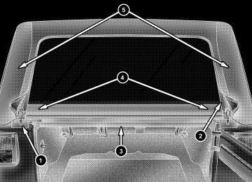
1 — Header Bow 2 — 2–Bow 3 — 3–Bow 4 — Sail Panel 5 — Body Side Retainer
6 — Quarter Window 7 — Check Strap 8 — Front Retainer — Quarter Window 9 — Bottom Retainer — Quarter Window
202 UNDERSTANDING THE FEATURES OF YOUR VEHICLE
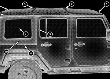
1 — Zipper Start 2 — Zipper Finish 3 — Swing Gate Bar 4 — Swing Gate Brackets 5 — Sail Panels
NOTE: Clean side and rear windows before removal to assist in preventing scratching during removal of the soft top. If zippers are difficult to operate due to road dust, etc., clean them with a mild soap solution and a small brush. Cleaning products are available through your authorized dealer. 1. If your vehicle has half doors, remove each half-door window by opening the door and lifting the half-door window out. NOTE: Stow the half-door windows carefully outside of the vehicle, never inside, to avoid scratches. 2. Unclip and move the sun visors to the side. 3. Release the header latches and leave the hooks in the loops on the windshield.
UNDERSTANDING THE FEATURES OF YOUR VEHICLE 203
4. Open the swing gate.
204 UNDERSTANDING THE FEATURES OF YOUR VEHICLE 5. Before unzipping the rear window, release the first 3 in (7.6 cm) of both sail panels from the channel. Remove the swing gate bar by pulling it straight rearward out of the swing gate brackets.
• Unzip the rear window starting at the right lower corner of the window. Pull the zipper up, across the top and down to the left lower corner. Zipper pulls will stay on the rear window. Pull down on the rear window to disengage it from the zipper on the top cover.
6. Remove the rear window retainer from the swing gate bracket on both the left and right sides.
UNDERSTANDING THE FEATURES OF YOUR VEHICLE 205
9. Beginning from the rear lower corner, completely unzip the window.7. Stow the windows carefully to avoid scratching. 8. Undo the Velcro威 that runs along the top and rear edge of the side window.
10. Once unzipped, remove the side window retainers from the door channel and body side channel. Repeat this step on the opposite side.
206 UNDERSTANDING THE FEATURES OF YOUR VEHICLE 11. Finish releasing the sail panel retainers from the body side channel at the rear corners of the vehicle.
12. As you begin to lower the top, fold the sail panels so that they rest on top of the soft top.
NOTE: When releasing the sail panel retainers, it is helpful to pull down on the rear roof bow.
13. The swing gate brackets do not need to be removed unless the hard top is being installed. To remove the swing gate brackets, pull the front of the bracket forward while rolling the entire bracket back in toward the vehicle to disengage.
UNDERSTANDING THE FEATURES OF YOUR VEHICLE 207
14. Completely release the latches from the loops on the windshield frame. If your vehicle is not equipped with the Sunrider威 package, proceed to Step 15.208 UNDERSTANDING THE FEATURES OF YOUR VEHICLE 15. Make sure the plastic sleeves are slid rearward over the Sunrider威 link (Sunrider威 Models only).
16. Unlatch the side bows from both door rails (Sun- rider威 Models only).
17. Before lowering the top, open the swing gate to prevent possible damage to the rear center high-mounted brake light. Move to the front of the vehicle. Grasp the side bow behind the header and lift the top, folding it toward the rear of the vehicle. NOTE: Help from another person will ease this opera- tion.
UNDERSTANDING THE FEATURES OF YOUR VEHICLE 209
18. Tuck the fabric and the check straps between the bows and as far inward as possible. This will keep any portion of the top from flapping outside of the vehicle.
19. Close the front header latches. 20. Remove the door frames, if desired. Refer to “Door Frame” in this section for further information.
210 UNDERSTANDING THE FEATURES OF YOUR VEHICLE Raising The Soft Top
1. Unclip and move the sun visors to the side. 2. Install door frames, if removed. Refer to “Door Frame” in this section for further information. 3. Make sure the plastic sleeve is slid over Sunrider威 link (Sunrider威 Models only).
4. Standing on the side of the vehicle, lift the top by the side bow and the 2–bow (middle bow) up and over the sports bar until the header rests on the top of the windshield frame.
5. Make sure the Sunrider威 bracket on the side bows latches to the door rails (Sunrider威 Models only).
UNDERSTANDING THE FEATURES OF YOUR VEHICLE 211
6. Open the header latches and engage the hook on each side onto the windshield loops (do not close the latches).212 UNDERSTANDING THE FEATURES OF YOUR VEHICLE 7. If the swing gate brackets were removed, install them by hooking the rear edge of the bracket on the interior side of the body channel. Then, rotate it rearward and over the channel until it snaps onto the exterior part of the rail. To be properly located, the bracket must only be clipped to the shortened rail edge.
8. Move to the rear of the vehicle and gently pull the sail panels over the rear roof bow.
9. Partially install the sail panel retainers into the body side channel, leaving the last 3 in (7.6 cm) toward the rear window loose (on both sides). Pulling down on the rear roof bow (3–bow) will aid to reach the channel with the retainers.
UNDERSTANDING THE FEATURES OF YOUR VEHICLE 213
10. To install the side windows, affix the window tem- porarily by attaching to the Velcro威 in the rear corner. Start the zipper but close only about 1 in (2.5 cm).214 UNDERSTANDING THE FEATURES OF YOUR VEHICLE 11. Insert the front retainer of the window into the door channel, making sure the retainer is fully seated and properly positioned on the door frame. Failure to do so can result in wind and water leaks or damage to the window.
1 — Incorrect Insertion 2 — Correct Insertion
12. Insert the retainer along the bottom edge of the window into the bottom side channel, beginning at the front and working to the rear of the vehicle. Finish by closing the zipper completely and attaching the Velcro威 along the top and rear of the window. Repeat this step for the opposite side.
UNDERSTANDING THE FEATURES OF YOUR VEHICLE 215
216 UNDERSTANDING THE FEATURES OF YOUR VEHICLE 13. Locate the black swing gate bar. Slide the swing gate bar over the receiver at the bottom inside of the rear